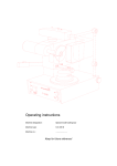
1
Operating instructions
Machine designation:
Triple workplace dust extraction unit
Machine type:
D-LE 260 E
Machine no.:
...........................
Keep for future reference!
Dear customer,
Thank you for the confidence you have placed in us by purchasing this triple
workplace dust extraction unit.
Please take time to read these operating instructions carefully, especially before using
the unit for the first time, as this will ensure that the unit will give you good service for
many years to come.
Contents
1
Safety..................................................................................................................... 2
1.1 Correct use ..................................................................................................... 2
1.2 Possible dangers ............................................................................................ 2
1.3 Approved operators ........................................................................................ 2
1.4 Safety measures at site of operation.............................................................. 3
1.5 Marking of safety references contained in these instructions ........................ 3
2
Starting up ............................................................................................................ 4
2.1 Technical data ................................................................................................ 4
2.2 Unpacking the triple workplace dust extraction unit ....................................... 5
2.3 Short description of unit and identification of components............................. 5
2.4 Starting up procedure ..................................................................................... 7
2.4.1 Pneumatic structure of tube/hose installation ...................................... 7
2.4.2 Structure of electrical installation ......................................................... 8
3
Operation ............................................................................................................ 11
3.1 Checking the filter system ............................................................................ 11
3.2 Automatic On-Off device / Connection of dust-generating devices.............. 11
3.2.1 Individual adaptation of extraction unit sensitivity to dust-generating
devices ............................................................................................... 12
3.3 Automatic air volume control ........................................................................ 12
3.4 Automatic shut-off and filter change control lamp ........................................ 12
4
Cleaning/Maintenance ....................................................................................... 13
4.1 Replacing the filter bag................................................................................. 13
4.1.1 Removing the filter bag ...................................................................... 13
4.1.2 Inserting the filter bag......................................................................... 14
4.2 Cleaning (replacement) of ultra-fine filter ..................................................... 15
4.2.1 Removing the ultra-fine filter .............................................................. 15
4.2.2 Fitting the ultra-fine filter..................................................................... 15
4.3 “Service” control lamp................................................................................... 16
5
Electrical fuse protection .................................................................................. 16
6
Warranty conditions........................................................................................... 17
7
EC declaration of conformity ............................................................................ 18
D-LE 260 E - 18.09.03 / Vers.: 1
1
1 Safety
1.1
Correct use
The D-LE 260 E triple workplace dust extraction unit is used in dental laboratories for extracting
dust produced when working with instruments which generate dust. It should never be used for
vacuuming liquids.
The unit is suitable for collecting category C dust in compliance with the requirements laid down
by the German Employers’ Liability Insurance Association (Berufsgenossenschaft) as defined in
ZH 1/487.
Unauthorized modifications and additions are not permitted for safety reasons!
The operating and maintenance conditions specified in these operating instructions must be
adhered to.
Caution The unit is not designed as a medical device!
Use on people is prohibited!
1.2
Possible dangers
-
Potential sources of ignition or combustible gases, vapors and liquids should not be extracted
with the Triple workplace dust extraction unit.
-
Switch off the unit and disconnect from mains power supply before carrying out maintenance
and cleaning work (pull out the mains plug).
-
Particular attention should be paid to ensuring that the filter bag and ultra-fine filter are always
installed correctly and undamaged, as the dust collected more or less poses a hazard to health!
-
The unit should be disconnected from the mains power supply before accessing the built-in
electrical components!
Danger The unit is not suitable for use in rooms where special conditions exist (e.g. corrosive or
potentially explosive atmospheres).
1.3
Approved operators
The operator of the unit should ensure that the operating instructions are accessible to the
operating personnel and have been read and fully understood. Only then should the operator
commission the unit.
2
D-LE 260 E - 18.09.03 / Vers.: 1
1.4
1.5
Note
Safety measures at site of operation
-
Air flowing out of the air outlet (14) should not be hindered in any way.
-
The unit should only be operated in cabinets or confined spaces if adequate ventilation is
provided and the ambient temperature resulting from unit operation does not rise by more than
(approx.) 10 °C.
-
The distance between the air outlet and the next obstacle (e.g. a wall or furniture) must be at
least 10 cm.
-
No foreign bodies should be inserted through the ventilation ducts on the unit.
-
Ensure that the workplace always complies with pertinent accident prevention regulations by
introducing appropriate internal company instructions and conducting inspections.
Marking of safety references contained in these instructions
Refers to tips and other particularly helpful information.
Caution Refers to particular methods of operation or handling, non-adherence to which can lead to
malfunctioning, damage or other problems.
Danger Refers to dangerous situations which can lead to injuries.
D-LE 260 E - 18.09.03 / Vers.: 1
3
2 Starting up
2.1
Technical data
Illus. 1: Side view with dimensions
4
Machine designation
:
Triple workplace dust extraction unit
Machine type
:
D-LE 260 E
Unit dimensions
:
Width
Depth
Height
Electrical connection
:
230 Volt/50 Hz
Overvoltage category
:
II
Power consumption
:
max. 900 W
The overall power consumption of all connected devices
(in total) should not exceed 2200 W.
Electrical fusing
:
2x 16 A/T
Air flow
:
max. 58 l/second
Extraction hose connection
:
Ø 50 mm
Dust collection
:
Up to approx. 10 kg (depending on dust type)
Weight
:
Approx. 26 kg
200 mm,
601 mm,
564 mm
(mains connection)
D-LE 260 E - 18.09.03 / Vers.: 1
2.2
Note
Unpacking the triple workplace dust extraction unit
Inspect the packaging and unit for transportation damage and report any damage detected
immediately to the haulage firm and/or supplier.
1. Place the carton on a flat surface.
2. Remove the top packaging material.
3. Push the packaging material away from the unit. Grasp hold of the unit by the lower edge.
4. The unit (weight = approx. 26 kg) should be lifted out of the carton by two persons.
5. Check the accessories:
2.3
-
Documentation
-
Mains power cable
-
See delivery note for further possible accessories
Short description of unit and identification of components
The D-LE 260 E triple workplace dust extraction unit has a powerful high-pressure fan which is
fitted with noise suppression. It is also equipped with an automatic electronic ignition, an
automatic shut-off feature with filter change indicator and automatic air volume control.
Pneumatic stop valves are connected and automatically actuated when the respective dustgenerating device is activated, enabling free airflow at the specified vacuum duct.
The automatic ignition electronics detect a rotating hand-held piece in a fraction of a second
and immediately actuate dust extraction. The connected stop valve (accessory) automatically
enables the extraction line immediately. Any commercially-available hand-held pieces can be
used for this purpose. The D-LE 260 E extraction unit is also used as an extractor for sand
blasting instruments, saws and other dust-generating devices, electronic detection functioning
here in the same manner.
The dust is collected in a double-ply disposable filter bag with a capacity of up to 10 kg,
depending on the nature of the dust.
The ultra-fine filter has a large surface area and is serially connected to the disposable filter
bag. It can even collect category C dust.1
1 Sicherheitstechnisches Informations- und Arbeitsblatt der Berufsgenossenschaft Nr.: 510210
(German Employers’ Liability Insurance Association safety information sheet)
D-LE 260 E - 18.09.03 / Vers.: 1
5
Illus. 2: Extraction unit components
1
2
3
4
5
6
7
8
9
10
11
12
13
14
15
16
19
A
B
D
E
Plate
Closure cover for filter bag
Ultra-fine filter cartridge
Ultra-fine filter cover
4x M5x30 flange bolts (no. 3)
Quick-action closure
Vacuum fitting Ø 50 mm (right)
Counteracting hook for quick-action
closure
Vacuum fitting Ø 50 mm (left)
Plastic fittings for filter bag
Filter bag
Wire basket
Mains connection socket 230V/50Hz
Air outlet cover
Electrical cabinet cover
Closure plug
2x main fuses
3x socket for dust-generating devices
3x socket for automatic stop valves
Ultra-fine filter chamber
Filter bag chamber
Illus. 3: Rear of unit
6
D-LE 260 E - 18.09.03 / Vers.: 1
2.4
Starting up procedure
-
2.4.1
Check filter system (see Section “3.1 Checking the filter system“).
Pneumatic structure of tube/hose installation
(see Illus. 2, Page 6, Illus. 4, Page 7 and Illus. 5, Page 8)
1. Establish a hose/tube connection to the dust-generating devices (select a hose length which is
a short as possible, maximum length approx. 2 m for each device).
2. The tube/hose installation is connected to the right fitting (7) or left fitting (9) of the extraction
unit. The remaining connection fittings on the housing (7 or 9) should always be sealed with the
plastic closure plug (16).
3. Connect the automatic pneumatic stop valve to the compressed air supply (pneumatic
connection (41), see Illus. 6, Page 9)
Note
All devices and installation components can be connected to the unit with flexible hoses or rigid
plastic tubes (see following examples).
variation of connection
with right angel
variation of connection with straight connecting branch
Illus. 4: Laying tubing to devices over long distances
1a
2a
3a
4a
5a
6a
90° angle piece Ø 50
Straight connection fitting Ø 50
PVC hose fitting Ø 50
Hose/Tube
Ø 50
T-piece Ø 50
T-piece connection fitting Ø 50
1
2
3
Dust-generating device no. 1
7a
9a
10a
11a
12a
37
T-piece connection fitting Ø 50
Reducer Ø 50 / Ø 45 / Ø 40
PVC hose fitting Ø 50 / Ø 45 / Ø 40
Hose/Tube
Ø 50 / Ø 45 / Ø 40
PVC hose fitting Ø 50 / Ø 45 / Ø 40
Automatic pneumatic stop valve
Dust-generating device no. 2
Dust-generating device no. 3
D-LE 260 E - 18.09.03 / Vers.: 1
7
T-piece: Ø 50 / Ø 40 turnable
T-piece: Ø 50 / Ø 50 turnable
Illus. 5: Laying tubing to devices over shorter distances
2.4.2
Structure of electrical installation
(see Illus. 6, Page 9)
1. Connect the dust-generating device mains power cable to sockets A (socket
Illus. 2, Page 6 and see Illus. 6, Page 9).
1, 2, 3 ) (see
2. Connect the stop valve connection cable to sockets B to (respective socket 1, 2, 3 ). Turn
the outer sleeve (39) of the connector (38) to the right to lock the connector in socket B
(bayonet lock).
3. Establish a connection to the mains power supply (230V/50Hz) with the mains cable provided
(socket (13)).
8
D-LE 260 E - 18.09.03 / Vers.: 1
Illus. 6: Unit and electrical connections
13
19
36
37
38
Mains power supply socket 230V/50Hz
Main fuses (2x 16 A/T)
Connection fittings Ø 50 mm
Automatic pneumatic stop valve
Connector with cable and solenoid valve socket
1
Designation for unit socket and stop valve
socket no. 1
2
Designation for unit socket and stop valve
socket no. 2
39
40
41
A
B
Outer connector sleeve with bayonet lock
Solenoid valve
Pneumatic connection
3x socket for dust-generating devices
3x socket for automatic stop valves
3
Designation for unit socket and stop valve
socket no. 3
Illus. 7: Laying lines to extraction unit
D-LE 260 E - 18.09.03 / Vers.: 1
9
4. Activate the main switch (20) (control lamp (21) illuminates green).
5. “Autom./autom.“ push button (22) illuminates green.
Electronic designation for an active consumer is activated.
-
6. Adapt extraction unit sensitivity to suit dust-generating devices (see section “3.2.1 Individual
adaptation of extraction unit sensitivity to dust-generating devices“).
7. The extraction unit begins continuous operation after the “Hand/manual“ push button (23) is
actuated (illuminates green).
Illus. 8: Plate with control elements
20
21
22
23
10
Main switch
Main switch control lamp (green)
”Autom./autom.“ automatic mode button
“Hand/manual“ continuous mode button
24
25
27
28
Push button for increasing air volume
Push button for reducing air volume
“Filter change“ control lamp
“Service“ control lamp
D-LE 260 E - 18.09.03 / Vers.: 1
3 Operation
3.1
Checking the filter system
(see Illus. 2, Page 6, Illus. 10, Page 14 and Illus. 11, Page 14)
Caution The D-LE 260 E triple workplace dust extraction unit should only be operated with a correctly
fitted, undamaged ultra-fine filter cartridge (3) and filter bag (11).
1. Remove the ultra-fine filter cover (4) (unscrew the 4x M5x30 flange bolts with a hexagonal
screwdriver (no. 3)).
2. Pull out the ultra-fine filter cartridge (3) by rotating and drawing it upwards (see Illus. 12, Page
15).
3. Ensure that the ultra-fine filter cartridge (3) is not damaged.
4. Screw in the ultra-fine filter cartridge (3) again to the limit stop so that it sits tightly on the fitting
in the ultra-fine filter chamber (D) (see Illus. 13, Page 15).
5. Screw the ultra-fine filter cover (4) to the housing with the aid of the 4x M5x30 flange bolts.
6. Remove the filter bag closure cover (2).
7. The filter bag (11) should be undamaged when inserted in the wire basket (12).
8. The plastic filter bag connection (10) should be fitted tightly to the connection fittings (7) or (9).
9. Fit the cover (2) and clamp tightly with the quick-action closure (6).
3.2
Automatic On-Off device / Connection of dust-generating devices
The extraction unit is equipped with an electronic On-Off actuator which reacts to most handheld pieces and other dust-generating laboratory devices.
Caution The power input of devices to be connected should not exceed 900 Watt per socket A (
1,
2, 3 ). The overall power input value of all connected devices should, in total, not exceed
2200 W.
1. Connect the dust-generating devices to sockets A ( 1, 2, 3 ).
2. Connect the automatic stop valves accordingly to sockets B ( 1, 2, 3 ).
3. The “Autom./autom.“ button illuminates green after the unit is switched on (main switch (20) ON)
(see Illus. 7, Page 9).
Note
Please contact our H+R Customer Service Dept. (tel.: +7181/9678-0) if devices other than those
which we have intended are to be connected! Please note Section “3.2.1 Individual adaptation
of extraction unit sensitivity to dust-generating devices“ prior to this.
The extraction unit starts automatically as soon as a connected dust-generating device is
activated. The unit stops after a delay of approx. 8 seconds if all connected devices are
deactivated.
It is possible to adapt the unit individually if it does not react to a particular dustgenerating device. Please contact the H+R Customer Service Dept. in this respect.
D-LE 260 E - 18.09.03 / Vers.: 1
11
3.2.1
Individual adaptation of extraction unit sensitivity to dust-generating
devices
(see Illus. 8, Page 10)
Note
All dust-generating devices should be connected to the extraction unit and any other devices
switched to stand-by mode (see Section “2.4.2 Structure of electrical installation“ in this
respect).
1. Activate the extraction unit at the main switch (20). The control lamp (21) illuminates green.
2. Depress the “Hand/manual“ button (23) continually:
-
The unit starts during this period
-
The extraction unit automatically reaches its highest vacuum level during operation after a
short period of time. The vacuum level is subsequently reduced automatically until the
vacuum motor is shut down.
4. The button (23) should only be released 3 seconds after the “Hand/manual“ button (23)
illumination is extinguished.
-
The extraction unit starts automatically after this
5. Actuate the “Autom./autom.“ button (22) briefly. The button (22) illuminates green and the
extraction unit changes to automatic mode.
3.3
Automatic air volume control
The air volume is increased or decreased to suit the number of dust-generating devices in
operation and is indepent of the degree of dirt in the filter. The air volume can be identified on
the illuminated LED’s (24 and 25). The set air volume is then maintained at a constant level by
electronic control until the automatic shut-off feature is triggered. The air volume can be altered
by actuating button (25) (to reduce the volume) or button (24) (to increase the volume). See
Illus. 8, Page 10.
Note
Illuminated LED (24) is equivalent to the minimum air extraction volume for one workplace.
Illuminated LED (24) is equivalent to the maximum air extraction volume of the unit.
3.4
Automatic shut-off and filter change control lamp
(see Illus. 2, Page 6 and Illus. 8, Page 10)
Note
An underpressure sensor triggers the automatic shut-off feature and the “filter change“ control
lamp (27) illuminates as soon as the max. permissible filter bag (11) filling level is reached. The
extraction unit and the connected dust-generating devices are switched off.
1. The filter bag (11) must be replaced (see Section “4.1 Replacing the filter bag“).
Note
The extraction unit can be switched on and off again or the filter bag (11) lightly beaten if the
automatic shut-off feature deactivates the unit. The unit can then operate for some more time
without changing the filter bag.
2. Open the clamp closure (6) and remove the closure cover (2) to lightly beat the filter bag (11).
Note
12
The ultra-fine filter cartridge (3) should be checked if the filter bag (11) is only slightly full after
the automatic shut-off feature is triggered (filter change lamp (27) illuminates). See Section
”4.2 Cleaning (replacement) of ultra-fine filter“.
D-LE 260 E - 18.09.03 / Vers.: 1
4 Cleaning/Maintenance
(see Illus. 2, Page 6)
Note
The extraction unit can be switched on and off again or the filter bag (11) lightly beaten if the
automatic shut-off feature deactivates the unit. The unit can then operate for some more time
without changing the filter bag.
Open the clamp closure (6) and remove the closure cover (2) to lightly beat the filter bag (11).
4.1
4.1.1
Replacing the filter bag
Removing the filter bag
(see Illus. 2, Page 6 and Illus. 9, Page 13)
1. Open 1x clamp closure (6) and remove the cover (2).
2. Press the filter bag (11) plastic fitting (10) off the unit fitting (7) with both hands.
3. Pull the filter bag (11) out of the extractor unit together with the wire basket (12).
4. Close the filter bag (11) with the attached closure cover (17).
5. Take the filter bag (11) and wire basket (12) to a disposal point.
Illus. 9: Removing the filter bag
Caution The disposable filter bag should never be emptied and reused as, apart from health
considerations, this will lead to malfunctions.
Note
Compressed air should not be used to remove any dust which is present from the filter
chamber (D or E)!
Note
See Section “4.2 Cleaning (replacement) of ultra-fine filter”.
D-LE 260 E - 18.09.03 / Vers.: 1
13
4.1.2
Inserting the filter bag
(see Illus. 2, Page 6, Illus. 10, Page 14 and Illus. 11, Page 14)
1. Fold the new filter bag (11) as shown in Illus. 9 and insert in the wire basket (12).
Illus. 10: inserting the filter bag
2. Push the new filter bag (11) together with the wire basket (12) into the extractor unit. The filter
bag connection (10) is fitted tightly onto the connection fittings (7) or (9) in the filter chamber
during this procedure.
3. Push the plastic connection (10) tightly onto the unit connection fitting (7).
4. Push the cover (2) under the Z-profile (18) in direction X on one side. Then move the cover (2)
downwards in direction Y and fit tightly to the housing.
5. Clamp the cover (2) with the quick-action closure (6).
Illus. 11: Fitting the filter bag cover
14
D-LE 260 E - 18.09.03 / Vers.: 1
4.2
Note
Cleaning (replacement) of ultra-fine filter
The ultra-fine filter cartridge (3) should be removed and replaced after approx. ten filter bag (11)
changes!
We will gladly clean the ultra-fine filter cartridge (3) as part of an exchange, using only filters
tested in accordance with ZH 1/487 Paragraph 2 (with test certificate complying with
DIN 24 184).
4.2.1
Removing the ultra-fine filter
(see Illus. 2, Page 6)
1. Remove the ultra-fine filter cover (4) by unscrewing the 4x M5x30 socket flange bolts (no. 3).
2. Rotate the ultra-fine filter cartridge (3) to remove.
Illus. 12: Removing the ultra-fine filter
Caution The sealing surfaces in the ultra-fine filter chamber (D) should be free of dust, as dust can
damage the vacuum motor.
The ultra-fine filter chamber (D) and filter bag chamber (E) should be cleaned by vacuuming.
Compressed air should never be used!!!
4.2.2
Fitting the ultra-fine filter
1. Press the cleaned or new ultra-fine filter cartridge (3) onto the plastic fitting in the ultra-fine filter
chamber (D) by rotating it.
2. Fit the cover (4).
3. Tighten the cover (4) firmly and evenly with the 4x M5x30 socket flange bolts (no. 3).
Illus. 13: Fitting the ultra-fine filter
D-LE 260 E - 18.09.03 / Vers.: 1
15
4.3
“Service” control lamp
The extraction fan should be replaced if the “Service“ control lamp (28) illuminates (see Illus. 8,
Page 10).
The extraction fan should only be replaced or checked by a qualified electrician.
5 Electrical fuse protection
(see Illus. 3, Page 6 and Illus. 6, Page 9)
The entire unit is protected by two 16 A/T (2x) fine fuses (19).
16
D-LE 260 E - 18.09.03 / Vers.: 1
6 Warranty conditions
This device conforms with current safety regulations and was subjected to extensive testing
before leaving the works.
We grant a 12 months guarantee in which we are obliged to carry out all repairs necessary as a
result of material or production faults free of charge.
Warranty limitations:
1. The guarantee is considered void if repairs are not carried out by specialized dealers or by us.
2. Spare parts deliveries made for reasons covered by the guarantee do not lead to an extension
of the original guaranty period.
3. Incorrect installation (e.g. failure to heed VDE* regulations or written installation instructions).
4. Incorrect operation or stress.
5. External influences (e.g. transportation damage, damage caused by impacting or blows,
damage caused by the effects of weather or other natural phenomenae).
6. Repairs and alterations not carried out by authorized third parties.
7. Unit breakdown resulting from adjustment, alteration or any other attempt to adapt the unit is not
considered a material or production fault. This guarantee neither encompasses the costs of
such adjustment, alteration or any other attempt to adapt the unit, nor remedying of the
resulting damage.
8. Normal wear and tear (e.g. spray nozzles, hoses, and including hand-held pieces, union nuts,
glass panes, carbon brushes, illumination agents) or damage resulting from incorrect operation
is not covered by the terms of guarantee.
In order to provide you with a comprehensive service we would like you to fill out the guarantee
return form (enclosed at the beginning of these instructions) and send it to us by fax or letter
(window envelope).
* Verband Deutscher Elektrotechniker (German Electrical Technician Association)
Fax no.: 0 71 81/ 73 13 9
--- ------------------------- ------------------------- -------------------------- ------------------------- -------------- für Fensterumschlag hier falten-------------- --
Duplicate
Guarantee return form
Machine
designation:
Triple workplace dust extraction unit
Maschine type:
D-LE 260 E
Maschine no.:
Date of purchase:
Dealer/Store:
Harnisch+Rieth GmbH & Co.
Maschinenbau
Postfach 1260
From:
73644 Winterbach
Date/signature:
7 EC declaration of conformity
as stipulated by the EC directive for machines
98/37/EC
We hereby declare that the design of the machine specified below conforms with basic safety
and health requirements of the listed EC directives.
This certificate is no longer valid in the event of modifications being made to the machine which
are not approved by us.
Name of the manufacturer
Address of the manufacturer
Machine designation
Machine type
:
:
:
:
Harnisch+Rieth
Küferstraße 14-16, 73650 Winterbach
Triple workplace dust extraction unit
D-LE 260 E
The following pertinent EC directives were applied:
EC machine directive (98/37/EC)
EC low voltage directive (73/23/EEC), equivalent to 1. GSG regulation of 11.06.79
EC EMC directive (89/336/EEC), equivalent to EMC law of 09.11.92
The following harmonizing standards were applied:
DIN EN 292
: Machine safety.
DIN EN 61 010-1 : Safety regulations for electrical measurement, control and laboratory
devices.
DIN EN 55 014
: Interference suppression of electrical devices and systems.
DIN EN 55 104
: Electromagnetic compatibility, noise resistance requirements (category I).
The following national technical specifications were applied:
ZH 1/487
: Device for collecting dust which poses a health risk and reintroducing fresh
air into workrooms.
Technical documentation is available.
The operation instructions relating to the machine are also available.
Director of the Quality Control Department
Winterbach, 15th March, 2000