1
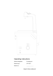
Operating Instructions
Machine designation:
Doubling Unit
Machine type:
D-D 860
Machine no.:
.......................
Keep for future reference!
Dear customer,
Thank you for the confidence you have placed in us by purchasing this doubling unit.
To ensure that this unit will be of service to you for many years to come, please take time to
read these operating instructions carefully, especially before using the unit for the first time.
Contents
1
Safety ..................................................................................................................... 2
1.1 Intended use ...................................................................................................... 2
1.2 Possible dangers ............................................................................................... 2
1.3 Approved operators ........................................................................................... 2
1.4 Safety measures at site of operation................................................................. 2
1.5 Marking of safety references contained in these instructions ........................... 2
2
Unpacking the doubling unit ............................................................................... 2
3
Operating and control equipment....................................................................... 3
4
Commissioning ..................................................................................................... 4
4.1 Short description of unit and identification of components................................ 4
4.2 Commissioning procedure................................................................................. 5
5
Operation ............................................................................................................... 7
5.1 Setting the melting temperature ........................................................................ 7
5.2 Setting the processing temperature .................................................................. 7
5.3 Manual intervention in program flow ................................................................. 7
5.4 Program interruption due to switching off or power cut..................................... 8
5.5 Counting device for monitoring of doubling mass quality.................................. 8
5.5.1 Setting value of max. melting processes.................................................. 8
5.5.2 Setting melting counter to zero ................................................................ 8
5.6 Safety equipment............................................................................................... 9
6
Cleaning/Maintenance........................................................................................ 11
7
Electrical fuse protection................................................................................... 11
8
Technical data ..................................................................................................... 11
9
Warranty conditions ........................................................................................... 12
10 EC declaration of conformity............................................................................. 13
D-D 860 - 06.07.2003 / Vers.: 2
1
1 Safety
1.1 Intended use
The D-D 860 Doubling Unit is used in dental laboratories for processing all commercially
available doubling masses.
Unauthorised conversions and alterations are forbidden for reasons of safety!
1.2 Possible dangers
−
−
−
The doubling unit is safe when used correctly, but there is, however, a danger of injury when
operated improperly (e.g., contact with the hot lid of the vessel, or contact with the hot
doubling mass).
The unit must be shut down at the main switch before carrying out maintenance and
cleaning work, and the connection to the mains power supply should be interrupted (pull
power supply plug out).
The unit must be disconnected from the mains power supply before any attempt is made to
access the built-in electrical components.
1.3 Approved operators
The operator of the unit should ensure that the operating instructions are accessible to the
operating personnel. The operator should ensure that they have been read and fully understood
by the operating personnel. Only then should they be allowed to operate the unit.
1.4 Safety measures at site of operation
The installation surface must be level and stable enough to support the weight of the doubling
unit. The unit should be installed in an environment which is as dust-free as possible. The rear
and both sides of the unit must be kept free to facilitate ventilation (approx. 15 cm clearance).
Ensure that no foreign bodies enter the ventilation apertures of the unit.
1.5 Marking of safety references contained in these instructions
Note
Refers to tips and other particularly useful information.
Caution
Refers to particular means of operation or handling, non-adherence to which can lead to
malfunction, damage or other difficulties.
Danger
Refers to dangerous situations which can lead to injury.
2 Unpacking the doubling unit
1.
2.
3.
4.
5.
Place the carton on a level surface.
Remove the upper packaging material.
Press the packaging material away from the unit and grasp the bottom edge of the unit.
The unit should be lifted out of the carton by two people (weight = 28 kg).
Check the accessories:
− Documentation
− Mains power supply connection cable ..............................................................No. 860 00 500
− see delivery docket for any possible further accessories
2
D-D 860 - 06.07.2003 / Vers.: 2
3 Operating and control equipment
Diagram 1: Frontal view
5
Digital display
− also designated as display
6
Push button, melting temp.
− Melting temp. is displayed when pressed
7
Potentiometer, melting temp.
− Remove protective cap to adjust.
8
LED diode, red
− Indicates heating phase
9
LED diode, yellow
− Indicates re-cooling phase
− Indicates processing readiness of doubling mass
10 LED diode, green
13 Potentiometer,
temp.
processing
− Remove protective cap to adjust.
14 Push button, processing temp.
− Processing temp. is displayed when pressed
15 Main switch
− Switching on unit
16 Push button, MF
− Button for additional functions
D-D 860 - 06.07.2003 / Vers.: 2
3
4 Commissioning
4.1 Short description of unit and identification of components
The doubling unit is fitted with a control system for automatic operation. Several temperature
sensors, operating independently of each other, monitor the melting and processing
temperatures, thus enabling overheating or coagulation of the doubling mass to be avoided. A
doubling mass with a homogenous temperature is ensured thanks to four separately controlled
heating elements with a temperature variance of ± 0.5 °C (max.). The set value and actual
value is displayed digitally. The vessel (which is easy to clean, being of a rust-free, stainless
steel construction) contains an efficient agitator. A draining valve (which is insulated against
heat) is fitted at the lowest point of the vessel.
Diagram 2: Frontal view from left
4
1 Plastic grip
17 Blow-off valve
2 Plastic lid
18 Control knob for drainage valve
3 Touch panel
25 Power connection contact
D-D 860 - 06.07.2003 / Vers.: 2
4.2 Commissioning procedure
(see diagram 1, page 3 and diagram 2, page 4)
1.
2.
3.
Switch off main switch (15) before establishing contact with mains power supply.
Connect to mains power supply (230 V/ 50 Hz) with mains power supply connection cable.
Fill with doubling mass:
− Fill with doubling mass, cut into pieces (approx. 4 cm in size), to approx. 2 cm below the rim
of the vessel.
− Lay up the lid (marking on the lid must be conform with point B)
− Bolt the lid (turn on the right side till to the stop-lug point A)
marking location of the lid
lay up the lid
A
B
A
B
marking location of the lid
bold the lid
marking location of the lid
Diagram 3: Lay up and bolt the plastic lid
D-D 860 - 06.07.2003 / Vers.: 2
5
4.
5.
6.
7.
Caution
Switch on unit at main switch (15). The main switch illuminates green.
The melting temperature is set in the unit at 92 °C. For changes to melting temperature see
section “5.1 Setting the melting temperature”.
The processing temperature is set in the unit at 48 °C. For changes to processing temperature
see section “5.2 Setting the processing temperature”.
Program flow:
− The program is started automatically when the main switch (15) is switched on, the melting
process begins and the agitator is activated after the temperature in the vessel has reached
40 °C. If the agitator encounters substantial resistance from the still solid doubling mass a
relief interval of approx. 20 sec. occurs. After these 20 sec. the agitator is activated again.
This procedure is repeated until the doubling mass has melted sufficiently to allow the
agitator to rotate freely. The period of time between the program start and agitator rotation
involves 10 to 20 minutes, depending on the doubling mass.
− As soon as the doubling mass subsides due to the melting process it can be topped up with
pre-cut doubling mass pieces to a point approx. 2 cm below the rim of the vessel.
Topping up with solid doubling mass may only be carried out below an actual temperature of 60
°C. This enables one to ensure that all doubling mass pieces have melted by the time the
melting temperature is reached.
− The entire doubling mass is completely melted in approx. 60 minutes. The melting heating
switches off; the cooling fan is activated, cooling it down to processing temperature in approx.
75 minutes. The agitator operates in continuous mode during the heating and cooling process,
until the set processing temperature is reached. From this point on the cooling fan switches off
and the agitator runs for a further 30 minutes, after which it switches to alternating agitation and
motionless intervals of 1 minute respectively. The individual heating elements heat according to
demand, regulated and impulse-controlled independently of each other, thus maintaining a
constant processing temperature throughout the vessel.
Note
On completion of work drain off any doubling mass residue which may be present in the
vessel and switch off the unit, or leave the unit with the doubling mass switched on until
the next working process begins.
If the doubling mass in the unit has coagulated it must be cut up and removed.
Caution
6
The agitator should under no circumstances be rotated with excessive manual force!
D-D 860 - 06.07.2003 / Vers.: 2
5 Operation
5.1 Setting the melting temperature
(see diagram 1, page 3)
1.
2.
3.
Remove protective cap from potentiometer (7).
Hold push button (6) in a depressed position and set the melting temperature on the
potentiometer (7) with the aid of a screwdriver (5 mm wide).
The temperature reading can be read on the display (5) while the push button (6) is depressed.
Please heed the information supplied by the doubling mass manufacturer!
Note
5.2 Setting the processing temperature
(see diagram 1, page 3)
1.
2.
3.
Remove protective cap from potentiometer (13).
Hold push button (14) in a depressed position and set the melting temperature on the
potentiometer (13) with the aid of a screwdriver (5 mm wide).
The temperature reading can be read on the display (5) while the push button (14) is
depressed.
Please heed the information supplied by the doubling mass manufacturer!
Note
5.3 Manual intervention in program flow
(see diagram 1, page 3)
Note
1.
Lowering of processing temperature setting, while the unit is at processing temperature (see
section “5.2 Setting the processing temperature”).
− The fan is switched on and cools the doubling mass down to the newly set lower processing
temperature.
2.
Raising of processing temperature setting, while the unit is at processing temperature, e.g.,
48 °C.
− Raising of processing temperature by more than 4 °C, e.g. from 48 °C to 54 °C (see section
“5.2 Setting the processing temperature”). The unit begins to heat the doubling mass up, i.e.,
heating to melting temperature in a heating phase, followed by a cooling phase down to the
newly set processing temperature (54 °C).
− Raising of processing temperature by less than 4 °C, e.g. from 48 °C to 50 °C. The doubling
mass is heated under control to the newly set processing temperature.
The procedure below should be followed if a renewed heating phase is triggered by raising the
processing temperature, and this has to be interrupted:
− Wait until the doubling mass temperature has risen above the newly selected processing
temperature.
− Switch the unit off and on at the main switch (15), simultaneously keeping the push button
(14) depressed.
− The heating phase is interrupted and the doubling mass cooled down to processing
temperature.
D-D 860 - 06.07.2003 / Vers.: 2
7
5.4 Program interruption due to switching off or power cut
Interruption during heating phase:
− The heating process continues automatically after the interruption.
Interruption during cooling phase:
− The cooling process continues automatically after the interruption and the doubling mass is
cooled down to processing temperature. If the doubling mass temperature has already
dropped to 4 °C under the processing temperature the doubling mass will be re-heated to the
melting temperature.
Interruption during processing:
− The unit continues the processing operation automatically after the interruption. If the
doubling mass temperature has already dropped to 4 °C under the processing temperature it
will be re-heated to the melting temperature.
5.5 Counting device for monitoring of doubling mass quality
(see diagram 1, page 3 and diagram 4, page 8)
− The quality of the doubling mass declines in relation to the number of melting processes it goes
through. Please heed the information supplied by the doubling mass manufacturer.
− The number of melting processes undergone are counted electronically and shown on the
display when the MF button (16) is pushed.
Caution
If the number of processes counted (20) reaches the value of the input “max. melting
processes (21)” (see section 5.5.1) it is indicated on the display by a blinking arrow (19). This
display is purely informative and does not affect the program flow.
5.5.1 Setting value of max. melting processes
(see diagram 1, page 3 and diagram 3, page 7)
Note
The “max. melting processes” value is set at 5 by the manufacturer.
1. Switch the unit on at the main switch (15), simultaneously keeping the MF button (16)
depressed.
2. Release MF button.
3. Each activation of the button (6) raises the value of maximum melting processes (21) by 1. If
the max. possible value of 31 is exceeded the display restarts at “00” again.
4. The “max. melting processes” value is accepted (inputted) by turning the unit off and on at the
main switch (15), and the adjusting mode is exited.
5. The first value on the display (menu number (35)) cannot be altered.
21 set max. number of melting processes
35 Menu no. (not alterable)
Diagram 4 : Display in adjusting mode
5.5.2 Setting melting counter to zero
(see diagram 1, page 3 and diagram 4, page 8)
1. The melting counter (20) is set to zero while the unit is switched on by pressing the MF button
(16) and the push button (6) simultaneously.
2. Release MF button.
3. The “00” value of the melting counter (20) can be checked on the display by pressing the MF
button.
8
D-D 860 - 06.07.2003 / Vers.: 2
19 Arrow blinks when “max. melting
processes” setting is reached
20 Counter for melting processes (melting
counter)
21 Set max. number of melting processes
Diagram 5: Display
−
The “melting counter (20)“ and “max. number of melting processes (21)“ values are separated
by a colon.
5.6 Safety equipment
(see diagram 2, page 4 and diagram 5, page 8)
−
−
−
−
−
Note
The agitator is switched off automatically by a safety switch when the lid (2) is opened. After lay
up the lid it must be noticed, that the marking on the lid is conformed with the point B. Turn the
lid to the right side until the lid is bolt on the stop-lug on point A. The agitator can be reactivated
now by the control system.
An in-built, bi-metallic time delay switch (31) protects the unit against overheating by switching
off the complete power supply at approx. 110 °C. It does not reset itself automatically when
cooling down occurs.
The unit must be switched off at the main switch and the connection to the mains power
supply interrupted (pull mains power supply plug out).
Remove the casing at rear of unit by unscrewing the screws (32).
Resetting occurs when the black resetting pin (30) on the bi-metallic time delay switch (31) is
pressed.
If the red and green LED’s are blinking, and “Err” appears on the display, this indicates that:
− The unit has overheated, or
− the motor has been put under too much pressure.
Please consult the Harnisch+Rieth customer service department if this should occur.
30 black resetting pin on bimetallic time delay switch
31 bi-metallic time delay
switch
32 4x screws for casing at
rear of unit
Diagram 6: Bi-metallic time delay switch (rear casing removed)
D-D 860 - 06.07.2003 / Vers.: 2
9
6 Cleaning/Maintenance
(see diagram 2, page 4)
−
−
The doubling mass container should be cleaned of foreign bodies and sediment regularly and
subjected to hot flushing to avoid any adverse effects on the drainage valve (17)!
The contact bracket recess (3) (safety switch) should always be kept clean.
7 Electrical fuse protection
−
−
The mains power supply connection (25) is fused with two main 8 A/T fuses (26). They are
located on the right side of the unit.
The control system (control panel) is fused with a 0.315 A/M fine-wire fuse. It is located on the
panel.
25 Unit mains power
supply plug
26 Main fuses
Diagram 7: Main fuses
8 Technical data
10
Machine designation
: Doubling unit
Machine type
: D-D 860
Unit dimensions
: Width 390 mm,
Depth 370 mm,
Height 525 mm
Electrical connection
: 230 volt/50 Hz
Excess voltage category
: II
Power consumption
: max. 800 Watt
Electrical fuse protection
: 2x 8 A/T
Weight
: approx. 28 kg.
(main fuses)
D-D 860 - 06.07.2003 / Vers.: 2
9 Warranty conditions
This device conforms to the present safety regulations and was subjected to extensive testing
before leaving the works.
We grant 24 months guarantee, in which we are obliged to carry out all repairs resulting from
material or fabrication faults free of charge.
The warranty expires if repairs are not carried out by specialized dealers or by us.
Replacement for reasons covered by the guaranty does not lead to an extension of the original
guaranty period.
Normal wear and tear or damages resulting from incorrect operation are not covered by the
terms of warranty.
In order to be able to provide you with a comprehensive service we ask you to fill out the
guarantee return form (attached at the beginning of these instructions) and send it to us by fax
or letter (window envelope).
Fax no.: 0 71 81/ 73 13 9
-------------------------------------------------------------------------------------------------------------
Copy
Guarantee return form
Machine
designation::
Doubling Unit
Machine type:
D-D 860
Machine no.:
Date of purchase:
Dealer/Store:
Maschinenbau
Harnisch+Rieth GmbH & Co.
Postfach 1260
From:
D-73644 Winterbach
Date/signature:
Fold here for window envelope ----
10 EC declaration of conformity
as stipulated by the EC directive for machines
89/392/EEC, Appendix II A
We herewith declare that due to its design the machine specified below is in conformity with
the basic safety and health requirements of the EC directives.
In the event of modifications of the machine not approved by us this certificate looses its
validity.
Name of the manufacturer
Address of the manufacturer
Machine designation
Machine type
:
:
:
:
Harnisch+Rieth
Küferstraße 14-16, 73650 Winterbach
Doubling Unit
D-D 860
The following pertinent EC directives were applied:
EC machine directive (89/392/EEC), corresponding to 9. GSG regulation of 12.05.93
EC low voltage directive (73/23/EEC), corresponding to 1. GSG regulation of 11.06.79
EC EMC directive (89/336/EEC), corresponding to EMC law of 09.11.92
Following harmonizing standards were applied:
DIN EN 292
: Safety of machines.
DIN EN 61 010-1
: Safety regulations for electrical measuring, controlling and laboratory devices.
DIN EN 55 014
: Interference suppression of electrical apparatus and installations.
DIN EN 55 104
: Electromagnetic compatibility, noise resistance requirements (category I).
A technical documentation is available.
The operation instructions belonging to the machine are also available.
Director of the Quality Control Department
Winterbach, 06th September, 1995