1
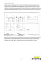
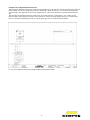
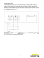
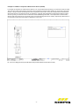
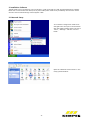
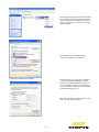
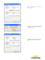
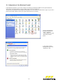
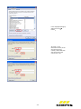
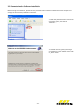
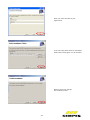
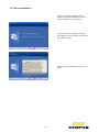
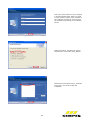
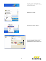
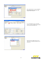
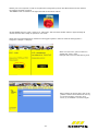
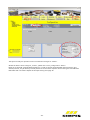
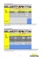
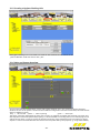
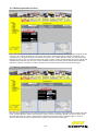
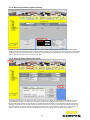
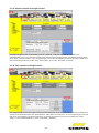
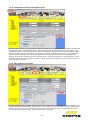
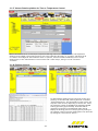
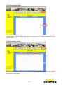
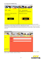
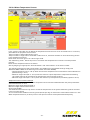
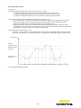
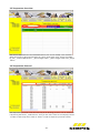
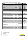
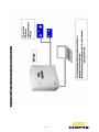
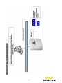
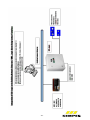
Installation and Operating Instructions KEMPER KHS Logic Control System Figure 686 02 003, Individual Design Table of Contents 1. Installation Hardware 1.1 System requirements for computer or laptop on the part of operator 1.2 Application Area 1.3 Setup 1.4 Structural Setup 1.4.1 Switch Case Exterior Buttons 1.5 Hardware Components 1.6 Circuit Diagram 2. Installation Software 2.1 Network Setup 2.1.1 Adaptation of the Windows Firewall 2.2 Parameterization Software Installation 2.3 Twincat Installation 3. Parameterization Software 3.1 Sample Object 3.1.1 Creating A-Valves 3.1.2 Creating B-Valves 3.1.3 Creating C-Valves 3.1.4 Creating Sensors 3.1.5 Creating a Hygiene Flushing Unit 3.1.6 Valve and Sensor Overview 3.1.7 Manual Operation A-Valves 3.1.8 Manual Operation B-Valves 3.1.9 Manual Operation A-Valves and B-Valves as a Group 3.1.10 Manual Operation C-Valves 3.1.11 Manual Operation Hygiene Flushing 3.1.12 Group Volume Control via B-Valve 3.1.13 Volume Control via Single A-Valve 3.1.14 Time Control via Single A-Valve 3.1.15 Temperature Control via Single A-Valve 3.1.16 Time Control via C-Valve 3.1.17 Volume Data Acquisition for Time or Temperature Control 3.1.18 Flushing Protocol 3.1.19 Current Fault Messages 3.1.20 Fault Message Archive 3.2 Temperature Monitoring 3.3 Project Creation 3.4 Hot Water Temperature Sensors 3.4.1 Temperature Protocol 3.5 Temperature Overview 3.6 Temperature Protocol 4. Table: Wiring Information for Individual Components with KHS Logic 5. Connection to Laptops, Networks or BMS -0- p.1 p.1 p.1 p.1 p.2 p.2 p.3 p.3 p.9 p.9 p.13 p.15 p.17 p.25 p.25 p.26 p.26 p.27 p.27 p.28 p.28 p.29 p.29 p.30 p.30 p.31 p.31 p.32 p.32 p.33 p.33 p.34 p.34 p.35 p.35 p.36 p.36 p.37 p.38 p.39 p.39 p.40 p.41 1. Installation Hardware 1.1 System requirements for computer or laptop on the part of operator Following system requirements are needed for installation parameterization software on computers or laptops: 1. Windows 2000 (32 bit) 2. Windows XP (32 bit) 3. Windows Vista (32 bit) 4. Windows 7 (32 bit) Internal clock: 600 MHz or faster Main memory: 256 MB RAM or bigger Hard disc with min. 512 MB or bigger CD-ROM drive Screen resolution: 1024 x 768 For computers, which operate with 64 bit, we would recommend to set the above-mentioned systems on 32 bit via "virtual machine". 1.2 Application Area The KHS Logic Control System provides a central interface for the automated flushing process of an entire facility. It comprises a programmable control unit where the flushing programs are stored and which is compatible with all KHS servomotors and sensors. The user can select the required operation mode in a targeted manner by entering operation types such as time control, temperature control or volume flow control, while parameterizing the flushing volumes or periods previously established via simulation within the KHS Logic. 1.3 Setup The system is controlled via an SPC in the shape of a top hat rail PC. A further local computer (e.g. laptop or host computer, if available) is required in order to parameterize the system using the parameterization software included by executing freely selectable servomotor activation combinations with the sensors. Special Safety Information - The components may only be installed and taken into operation by qualified professionals familiar with applicable national standards. - The system in hand carries potentially harmful currents. These voltages can cause extensive damage to property and serious to life-threatening injuries. - The system operator is required to ensure that the system is only used as intended. - The maximally permitted ambient temperature is 55°C. - The switch case system delivered is protected in compliance with IP 55. If the switch case is subsequently modified we are unable to accept any liability in terms of contact, foreign body and water protection. -1- 1.4. Structural Setup e) b) a) b) c) a) c) d) e) f) d) g) Pic. 0-1 Switch Case Interior Structure Pic. 0-2 Switch Case Exterior Structure a) CX_9000 computer + Beckhoff module terminal b) Automatic cut-out c) 24V power supply unit d) Terminal blocks e) 6A service socket f) Cable entry a) Quick stop b) Ready c) Manual d) Automatic e) Fault f) Flushing in progress g) Main switch 1.4.1 Switch Case Exterior Buttons Quick Stop The quick stop button sets the system to a defined initial state (for example in case of damaged duct system). This means that any flushing processes that may be in progress are discontinued and the servomotors are set to their rest position (closed). No new flushing processes will be started until the root cause of the fault has been eliminated and the system is set to „Ready“ again. To this end the respective fault needs to be acknowledged in the parameterization software (button „Fault Messages“, see Section 3.1.19). Only then will the system be ready for operation once more and be able to perform all the parameterized flushing processes as desired. Ready Besides the function described above, the „Ready“ button is also needed to start the system once it has been installed and taken into operation. Manual “Manual operations“ in the parameterization software (see Section 3.1.8ff) are signalled by the „Manual“ LED. Automatic Indicates the „Automatic“ operating mode. This is activated as soon as the operator deselects the “Manual” operating mode in the parameterization software (see Setion 3.18). Fault The „Fault“ signal lights up permanently if one of the listed errors occurs in the system. The following faults can occur: - No valve feedback (opening) - No valve feedback (closing) - Canal flooding - No B-valve assigned - System in quick stop - Safety fuse in switch case activated -2- The following table (Tab.:1 Fault Messages) describes the errors causing the activation and their respective impact on the system. If only the group of the valve is closed, the other groups or individual valves will continue operating. If the entire system is shut off, no further valve will be activated until the error to have occurred has been eliminated and acknowledged. Fault No valve feedback (opening) No valve feedback (closing) Canal flooding No B-valve assigned System in quick stop Safety fuse in switch case activated Fault Description Fault message occurs if valve does not report “open” after the preset opening period + 10 seconds tolerance (factory configured setting). Fault message occurs if valve does not report “closed” after the preset opening period + 10 seconds tolerance (factory configured setting). If the valve group or individual valve overflow protection has activated a B-valve or C-valve. If no B-valve (group valve) is assigned to an A-valve. The quick stop button has been activated The automatic cut-out in the switch case has been activated Impact Group of the valve is blocked Group of the valve is blocked Group of the valve is blocked Group of the valve is blocked Entire system is blocked Entire system is blocked Flushing in Progress This LED is activated as soon as a flushing process occurs in the system, taking into account the A-valves (servomotors open/close), C-valves (servomotors with spring reset) and hygiene flushing units. No new transmission is possible from the parameterization software while a flushing process is active. 1.5 Hardware Components The hardware components generally comprise a Rittal terminal box, a Beckhoff CX_9000 top hat rail PC and several Beckhoff terminals. The KEMPER KHS Logic control system (Figure 686 02 001, Figure 686 02 002 and Figure 686 02 003) is offered in flexible system sizes differentiated by the number of resources to be used. The resources in this case include all the servomotors, temperature and throughput measurement fittings, overflow protection devices and hygiene flushing units. 1.6 Circuit Diagram The included circuit diagram makes the installation of individual resources easier. The circuit diagram is composed of several parts. Cover page Table of Contents Terminal Connection Input Overview of SPC Modules Used (Beckhoff) Terminal Connection: o 24V voltage generation o Drain with overflow monitoring o Hygiene flushing unit o Servomotors o Cold water temperature measuring devices Pt 1000 o Hot water temperature measuring devices Pt 1000 o Throughput measuring devices o 5V voltage generation Cable overview Parts list -3- Example Servomotor Type A Selecting the page of the respective canal. This is identified via the page title (see Ill. 1-3a) and servomotor description field (see Ill. 1-3b). Both connection options, i.e. for type A servomotors, Fig. 68600, as well as the servomotors with spring reset type B and C, Fig. 68601, are shown on the page of each valve (see Ill.1-3 d)). A servomotor of the Fig. 68600 is used in our example (see Ill. 1-3 c). The servomotor needs to be connected as indicated in the left image section or Table 2. This means that the blue (bl) and the red (rt) wire need to be connected to a free series terminal designated as 24L-, and the brown (br) wire to a free 24L+ series terminal. In our example the black wire (sw) needs to be connected to module terminal A231/1 (see Ill.1-3 e) and the grey wire (gr) to module terminal A331/1 (see Ill: 1-3 f). b) e) f) d) c) a) Pic. 1-3 Circuit Diagram Excerpt (Servomotor Type A V101) Please make sure to check the terminal connections before the first start-up. If the valve channels, for example A231/1 and A331/2, should be mixed up when connecting a servomotor, the control unit will fail to work properly and the functioning of the hygiene system unit can not be guaranteed. Testing all the settings and terminal connections in the “Manual” operating mode is hence recommended. Please see Section 3.1.8 for a detailed description of the „Manual“ operating mode and the attendant parameterization window. -4- Example 2 Throughput Measurement Device A permanently assigned channel also needs to be selected here, as was the case with the servomotors. Please use channel D101. The channel assignment process is described in detail in Section 3.1.5. The channel designation can be found in the page title of the circuit diagram (see Ill. 1-4a) or the description of channel D101 (see Ill. 14b). The throughput measurement device needs to be connected as shown in Illustration 1-4 or in Table 3. This means that the yellow (ge) wire needs to be connected to a series terminal designated as 5L+, the white (ws) wire to a series terminal designated as 5L- and the green (gn) wire to module terminal A351/1. b) c) a) Pic. 1-4 Circuit Diagram Excerpt (Throughput Measurement Device D101) -5- Example 3 Hygiene Flushing In the example, hygiene flushing unit 1 is connected to channel E101. The channel number permanently assigned to the hygiene flushing unit can also be found in the page title (Ill. 1-5a)) and the description of the respective channel (Ill. 1-5b)). The hygiene flushing unit needs to be connected as shown in Illustration 1-5 or Table 4. This means that connection 1 of the hygiene flushing unit needs to be linked to a series terminal designated as 24L+ and connection 2 with a 24L- series terminal. Connection 3 (Flushing in Progress) is linked to the module terminal KL1184 with the designation A121/1 (Ill. 1-5 c) br), connection 4 (Fault) to module terminal KL1184 with the designation A121/2 (Ill. 1-5d) gr) and connection 5 (Start Flushing) to module terminal KL2408 with the designation A221/1 (Ill. 1-5 d) rt). b) c) d) e) a) Pic. 1-5 Circuit Diagram Excerpt (Hygiene Flushing Unit E101) -6- Example 4 Cold Water Temperature Measurement Device (PT1000) In example 4, temperature measurement device 1 for cold potable water flushing is connected to channel T101. The channel number permanently assigned to the temperature measurement device can be found in the page title (Ill. 1-6 a)) as well as the description of the respective channel (Ill. 1-6 b)). The temperature measurement device needs to be connected as shown in Illustration 1-6. Both the temperature measurement device’s white wires are jointly connected to the module terminal KL3202 designated as R-. The temperature measurement device’s red wires need to be connected to the card entries designated as R+ and RL, respectively. Which wire is connected to which terminal makes no difference in this case. b) a) Pic. 1-6 Circuit Diagram Excerpt (Cold Water Temperature Measurement Device T101) -7- Example 5 Hot Water Temperature Measurement Device (PT1000) This example shows the installation of a hot water temperature sensor (Figure 628/629). As in the preceding examples, the permanently assigned channel number can be found in the page title (Ill. 1-7 a)) and the description of the respective channel (Ill. 1-7 b)). The hot water temperature measurement device needs to be connected as shown in Illustration 1-7. Both the temperature measurement device’s white wires are jointly connected to the module terminal KL3202 designated as R-. The temperature measurement device’s red wires need to be connected to the card entries designated as R+ and RL, respectively. Which wire is connected to which terminal makes no difference in this case b) a) Pic. 1-7 Circuit Diagram Excerpt (Hot Water Temperature Measurement Device T101) -8- 2. Installation Software The SPC needs to be connected to a local computer in order to be able to install the parameterization software. Please use a common Ethernet cable (cross or patch cable) which needs to be provided by the customer. Switch the main switch of the KHS-Logic Control System “ON”. 2.1 Network Setup Your network configuration needs to be changed first to set up the communication with the hygiene system switch case. Go to “Start”, “Settings” and then “Control Panel” Open the “Network Environments” in the newly opened window. -9- The network environments window displays your network cards. Right-click the network card connected to the hygiene system and click on “Properties“ in the pop-up window appearing next. Now highlight the „(TCP/IP) Internet protocol“ and click on „Properties“. a) Adding an Additional IP Address Advice: Should your computer be preset to “Use the following IP addresses”, please follow the further steps listed under a). If your computer is preset to „Automatically obtain IP address“, please follow the further steps listed under b), p. 12. Click the „Extended“ button in order to be able to create a new IP address. - 10 - Please click the „Add“ button under the „IP Settings“ tab title. In the newly opened window, enter the figures shown in the picture on the left and then click on „Add“. If the IP address just entered has now been added under „IP Addresses“, confirm with „OK“. - 11 - b) Alternative Configuration of a User-Defined IP Address Should your PC be set to automatically referring to an IP address, click on the tab title „Alternative Configuration“. Now enter the addresses as shown in the picture on the left. - 12 - 2.1.1 Adaptation of the Windows Firewall If the Windows firewall on your local computer is enabled, ports BF02 and BF03 must be opened because otherwise the steps described on page 21 (add route) cannot be carried out. To open the port, please work through the steps below. You must have the administrator rights to your PC to perform these steps. Please contact your system administrator if necessary. To go to the Windows firewall settings, go to "Start" "Settings" "Control Panel" and click "Windows Firewall" twice. In the newly opened dialogue box, go to the "Exceptions" tab. - 13 - In the displayed dialogue, select the "Port…" button. As shown in the illustrations below, enter the name and port number, select UDP each time and confirm the entries with "OK". - 14 - 2.2 Parameterization Software Installation Before starting the installation, please insert the parameterization software included in the local computer and comply with the following installation operations. To install the parameterization software for the hygiene system, start the file „setup.exe“. The installer will now guide you through the installation process. Please confirm with the „Next“ button. - 15 - Enter your name and that of your organization. In the next step, please select an installation folder where the program is to be installed. Please confirm your settings. The installation starts. - 16 - 2.3 Twincat Installation Once the parameterization software is installed, an additional Beckhoff tool will also be installed on your computer. The installer will now guide you through the installation process. Please confirm with the “Weiter” button. Accept the license agreement with the „Ja“ button. - 17 - Enter your name and that of your company in the appropriate fields. There is no need to enter a serial number, as the software to be installed is royalty-free. Continue with the installation by clicking on the “Weiter” button. Select the product „TwinCAT CP- Control Panel Drivers“ and confirm with „Weiter“. Deactivate the checkbox next to „TwinCAT Scope View“ and continue with the installation. - 18 - Enter the installation folder and click on “Weiter”. Also confirm this window with „Weiter“. The installation is completed. The computer needs to be restarted. Click on “Yes, restart computer now”, and then on “Fertig stellen” (if the computer fails to restart automatically, perform a manual restart). - 19 - Once the computer has restarted, a new symbol will appear in the task bar, as shown in the picture on the left. Right-click on the symbol. Now left-click on „System Manager“. The system manager of the TwinCAT System has been started. Now click the button [Select Destination System], as shown in the picture on the left. - 20 - Please click on „Search (Ethernet)“ in the new window. A new mask will open. Click on the „Broadcast Search“ button. This will start a search for the control unit. Once the search is completed, the CX_9000 should be displayed as shown in the picture on the left. Highlight it, click on “IP Address” once and then click on „Route zufügen“. - 21 - Enter „Administrator“ in the “User Name” box. Please leave the “Password” field empty. Confirm with OK An „X“ will appear in the „Connected“ column once the CX_9000 has been added. You can close this window now. Highlight the CX_9000 and click on the „OK“ button. The system manager can be closed now. - 22 - Restart your local computer in order to complete the configuration process. The SPC furthermore also needs to be restarted. Proceed as follows: The ON/OFF switch is located on the right-hand side of the switch cabinet. Set the ON/OFF switch to „OFF“, and then to „ON“ again. This will restart the SPC. Wait for approximately 30 seconds until the SPC is ready for operation once more. Please open the parameterization interface for the hygiene system in order to check the settings (Start -> Programs -> Kemper -> Kemper). Select one of the two „Start“ buttons to activate the „Start“ mask. Example: Start menu for KHS flushing units. After creating the project data, click on the „Offline“ button. The software will now try to connect. Should a connection error occurs, try to establish a connection again. - 23 - The system is ready for operation as soon as the button changes to “Online”. Should the button fail to change to „Online“, please click on the „Configuration“ button. Please go to the field “Change Network Settings” in order to change the KHS LOGIC network settings. This should, however, only be done by trained personnel. Confirm with “Update” after entering the new addresses. KHS LOGIC will now restart. Repeat all the steps starting from page 18. - 24 - 3. PARAMETERIZING SOFTWARE 3.1 Sample Project Note: The system requirements must be fulfilled (see chapter 1.1). The sample project shall help explain the parameterization software more clearly. An overview is shown in Ill. 31. The project involves three type A servomotors, an attendant type B group servomotor, a type C servomotor and a hygiene flushing unit (S1). The sensors included for this project include 2 PT 1000 temperature measurement devices (T1, T2) and a vortex flow sensor (V1). Valve A3:V103 Building2; 3. floor Floor 3 Flushing unit S1:E101 Building 2, 2. floor Valve A2:V102 Building 2; 2. floor = User floor Floor 2 Valve A1:V101 Building2; 1. floor Valve B1:V104 Group A1, A2, A3 Floor 1 Temperature sensor 2 Output T102 Throughput sensor Valve C1:V105 Building2; 1. basement Temperature sensor 1: Input T101 Pic. 3-0-1 Sample Project Overview The sample project serves to illustrate the creation and parameterization of the time control, volume control and temperature control programs. In the start window you should assign a name to the project and system. While creating the project, please use the circuit diagrams of the actuators and sensors for assigning the appropriate channels. - 25 - 3.1.1 Creating A-Valves Please proceed as follows in order to configure the hardware: Go to the tab index “A-Valves”. There are three Avalves provided with the channel numbers 101, 102 and 103, as shown symbolically at the front. The first A-valve is displayed under the valve number. Assign channel 101 to this valve in the „Channel Number“ field. If you now click the “OK” button the valve is established in the program. The tree on the left-hand side will then show the first created A-valve. Repeat the process for A-valve 2 and A-valve 3, assigning the channels 102 and 103, respectively. 3.1.2 Creating B-Valves The tree on the left now shows the three created A-valves. Open the tab index “B-Valves” in order to create the attendant B-valve. In the sample project, the B-valve is assigned channel 104, which needs to be selected in the “Channel Number” field accordingly. As all three A-valves created belong to this B-valve, the checkboxes for Avalve 1, A-valve 2 and A-valve 3 all need to be activated in the field “Assigned A-Valves”. Please click on “OK” in order to create the set-up. B-valve 1 should now also appear in the tree on the left-hand side. - 26 - 3.1.3 Creating C-Valves To create a C-valve, please open the „C-Valves“ index tab. C-valve 1 is assigned channel 105, as shown in the illustration. Select this channel again in the „Channel Number“ field and confirm with the „OK“ button to establish the C-valve. 3.1.4 Creating Sensors The sample project requires a sum total of three sensors to be created. The type 200l/min volume sensor needs to be connected to sensor channel D-101 and confirmed with the “OK” button. The temperature sensors comprise one input sensor on channel T-101 and one output sensor on channel T-102. Please establish both the sensors, confirming with “OK” each time. - 27 - 3.1.5 Creating a Hygiene Flushing Unit The hygiene flushing unit is connected to channel HS-101. Please enter this channel in the „Channel Number“ field and confirm with „OK“. 3.1.6 Valve and Sensor Overview You can now view the created valves, sensors and hygiene flushing unit in the “Valve and Sensor Overview” window. As soon as the system is online and the hardware configuration has been transmitted, the valves will be shown in different colours: Grey valve closed yellow valve is opening green valve open The sensor values are displayed at the same time. To gain an overview of whether the electrical connection and data acquisition have been performed properly, it is recommended to manually perform a so-called program run and functional check, in order to ensure the proper functioning of the individual sensors and valves. For larger objects it is hence recommended that this function check is performed by two people (e. g. using walkie-talkies). - 28 - 3.1.7 Manual Operation A-Valves Each valve should now be tested manually, in order to see if all the impulses have been properly assigned to the created A-, B-, C-valves and flushing units. Please activate the “Manual Operation A-Valves” checkbox in the “Configuration” tab index. Select the A-valve to be tested in the “A-Valve Number” field. The selected A-valve should now start to open. Proceed by clicking the “Close” button and the A-valve should close again. Test all the established A-valves this way. Once you have completed the tests successfully, please deactivate the “Manual Operation A-Valves” checkbox, in order to be able to operate the system in the automatic mode again. 3.1.8 Manual Operation B-Valves Now test the single B-valve via the „Manual Operation B-Valves“ checkbox. Select the B-valve created previously in the „B-Valve Number“ field. Confirm with the “Open” button. The B-valve should now start to open. Close the valve again (button “Close”). Deactivate the “Manual Operation B-Valves” checkbox again, in order to discontinue manual operation and operate the system in the automatic mode again. - 29 - 3.1.9 Manual Operation A-Valves and B-Valves as a Group The „Manual Operation B-Valves“ checkbox can also be used to manually control a group. Select the B-valve and attendant A-valves. If you now click on “Open”, the first A-valve will start to open. As soon as it is fully open, the B-valve will start opening. Following the opening interval, the B-valve is closed first and then the A-valve. Once this is closed, the next A-valve will open, etc, in order to be able to operate the system in automatic mode again. 3.1.10 Manual Operation C-Valves To test the C-valve, go to „Configuration” and confirm „Manual Operation C-Valves”, select a C-valve and click on the “Open” button. After the successful test, close the C-valve again and terminate the manual control mode via “Manual Operation C-Valves“ again, in order to be able to operate the system in automatic mode once more. - 30 - 3.1.11 Manual Operation Hygiene Flushing A flushing is activated with the flushing units via „Manual Operation Hygiene Flushing“. Select the hygiene flushing unit first and then click on the “Open” button. Please note: The hygiene flushing unit can not be closed via the program but terminates after the flushing interval entered for the flushing unit, whereupon you will be able to operate the system in automatic mode again. 3.1.12 Group Volume Control via B-Valve To configure volume control via the B-valve, proceed as follows: Select the previously created B-valve in the „Valve Number“ field in the tab index „B-Valves“. Enter all the A-valves to be involved in a volume control (assigned A-valves). Select the volume sensor located before the B-valve. Set the weekday and attendant start time. Enter a flushing volume and maximum flushing interval. You can set up a maximum of five intervals per day. The B-valve can also be used to configure time control for a group. Please confirm with “valve accept” in order to save the values. To transmit the flushing process, please go to „File“ and then to „Transmit“. - 31 - 3.1.13 Volume Control via Single A-Valve To lodge a program in the single strand, go to the „A-Valves“ index tab and select the A-valve to be parameterized. In the case of volume control please ensure that the volume sensor is set before the assigned Bvalve. Select “Volume Control” in the “Program Type” box. Enter the weekday, start time, flushing volume and maximum flushing interval. Confirm with “valve accept”, go to “File” and select “Transmit”. 3.1.14 Time Control via Single A-Valve To configure time control via a single A-valve, proceed as follows: Go to the „A-Valves“ index tab and select the A-valve to be parameterized in the “Valve Number” field. Select “Time Control” in the “Program Type” box and then enter the weekday, start time and duration of the flushing process. Confirm your entries with “valve accept”. Then transmit the data via “File”, followed by “Transmit”. - 32 - 3.1.15 Temperature Control via Single A-Valve For temperature control via a single A-valve, select the A-valve to be configured in the „A-Valves“ tab index and the programme type “Temperature Control”. Select the previously created temperature output sensor in the “temperature Sensor” box. Enter the Delta K where the flushing is supposed to start in the “Temperature Start” field and the Delta K where the flushing is supposed to stop in the „Temperature Stop“ box. Then proceed to set the maximum flushing interval. Enter the times when a flushing may be performed in the appropriate “Flushing Times” boxes. Specify the time of the week when a compulsory flushing is to be performed in case no temperature flushing has occurred in the “Routine” field. Confirm your entries with „valve accept“, then go to „File” and select „Transmit“. 3.1.16 Time Control via C-Valve The final operation to be explained is time control via the C-valve. Go to the „C-Valves“ index tab and select the C-valve to be parameterized. Select “Time Control” in the “Program Type” field. Now enter the weekday, start time and duration in the appropriate fields. Volume control and time control can also be lodged via C-valves. Confirm with “valve accept”, go to “File” and then click on “Transmit”. - 33 - 3.1.17 Volume Data Acquisition for Time or Temperature Control With a volume flow sensor connected, the respective discharge volume of a temperature- or time-dependent flushing can be lodged in the flushing protocol. Go to the index tabs “B-Valves” or “C-Valves” and select the Bor C-valve to be configured. Then select the sensor in question, which is located immediately in front of the flushing valve, in the “Volume Sensor” field. Confirm with “valve accept”, then go to “File” and select “Transmit”. 3.1.18 Flushing Protocol To download the flushing protocol from the control unit, please go to the index tab „Flushing Protocol“ and select „Download Protocol“. The download from the control unit may take a few minutes, depending on the file size. Given the maximum number of 50.000 entries (equalling 50.000 flushing processes), approximately 10 minutes will be required until the file can be displayed and/or stored. Display the flushing protocol in the program by clicking on the “Display” button. Store the flushing data in an Excel file by clicking the “Save in Excel” button. - 34 - 3.1.19 Current Fault signals Clicking on the index tab „Fault signals“ will display the current fault messages and the fault message archive. The „Fault signals“ index tab will flash in red as soon as a malfunction occurs. To delete the fault, click on the “Update” button. 3.1.20 Fault signals archive Click the „Archives“ button in order to go to the fault signals archive, where all the faults to have occurred up to this point in time are displayed. The faults are shown in red as soon as they have occurred and in yellow once they have been acknowledged. - 35 - 3.2 Temperature Monitoring KHS temperature monitoring for hot potable water and potable water circulation monitors all the decisive temperatures in the hot water grid. A maximum of 100 sensors can be lodged in the parameterization software. This includes the storage of target values for every single temperature sensor. You can provide hot water temperature sensors in the temperature monitoring program and hence record the temperatures in the temperature protocol at defined monitoring times. To do this, click on “Start” and confirm with “OK”. 3.3 Project Creation Enter the project data in this window analogous to the KHS flushing unit start mask and click on the „Offline“ button in order to establish a software connection. - 36 - 3.4 Hot Water Temperature Sensors In the „Sensors“ tab index you can define the temperature sensors that are to be monitored later on. To do this, please define the properties of the sensors: The point where a thermal disinfection occurs. The point where a target value is exceeded or fallen short of, with these excessive or short values being written in the temperature protocol. Please enter the sensor type in the “Sensor Type” field. The “Monitoring Times” define the points in time when the temperatures are written to the temperature protocol. Please set the temperature sensors as follows: Start by assigning an appropriate “Channel Number” and “Sensor Name” to the sensor number. The following parameters need to be entered in the middle section (the default settings comply with Worksheet W551 / W553 of the German gas and water association DVGW): - Thermal disinfection (70 °C - 90 °C): Enter the minimum temperature to be reached for thermal disinfection (default setting is 70 °C). - Maximum target value (45 °C - 70 °C): Enter the reservoir output temperature. Temperatures exceeding this target value will be recorded in the temperature protocol (preset to 60 °C). - Minimum target value (40 °C - 65 °C): Enter the reservoir input temperature (circulation) (preset to 55 °C). Temperature Sensor Creation Example In the example shown above, a hot water temperature sensor has been established with the preset parameters: Thermal disinfection at 70 °C Maximum target value threshold at 60 °C Minimum target value threshold at 55 °C Sensor type: PT1000 The threshold values set here only serve to record the temperatures in the system! No flushing will be activated in the hot water system! You can furthermore establish monitoring times (6 times per day) for each sensor as described in Section 3.4 Hot Water Temperature Sensors, at which points in time protocol entries will be performed subsequently. - 37 - 3.4.1 Temperature Protocol Enrolment of - 6 temperature monitoring times in 24 hrs with defined T , T and T Mean Max Min - T = Mean temperature details for the six possible monitoring times (in 24 hrs) Mean - T = Maximum temperature details for the six possible monitoring times (in 24 hrs) Max - T = Minimum temperature details for the six possible monitoring times (in 24 hrs) Min - Times when a target value was exceeded or fallen short of (see Pic. 3.4) - Below target value = the point in time when the minimum temperature target value (e.g. 55°C) is fallen short of (8:00 o’clock and 14:00 o’clock) as well as the point in time when the minimum temperature target value is reached again (8:13 o’clock & 14:56 o’clock). - Over target value = The point in time when the maximum temperature target value (e.g. 60°C) is exceeded (11:24 o’clock & 12:51 o’clock) as well as the point in time when the maximum temperature target value is undercut again (11:31 o’clock & 13:29 o’clock). - Thermal disinfection times (see Pic. 3.4) The point in time when the “Thermal Disinfection” target value is exceeded (12:58 o’clock) as well as the point in time when the „Thermal Disinfection“ target value is fallen short of again (13:22 o’clock). Temperature Thermal Disinfection 70°C Maximum target value 60°C Minimum target value 55°C Time Pic. 3.4 Temperature/Time Diagram - 38 - 3.5 Temperature Overview The current temperatures of the established sensors can now be viewed in the overview. Select the sensors to be monitored from the „Filter“ drop-down menu. Sorting is possible by „All“, „Thermal Disinfection“, „Above Target Value“, „Below Target Value“ and „Target Value“. 3.6 Temperature Protocol The temperature protocol works the same way as the flushing protocol. You can download it by clicking the button „Load Protocol“ once you are online. Click on the “Display” button in order to view the protocol. Click on “Excel” in order to export the protocol to Excel. - 39 - 4. Wiring for KEMPER KHS components with electrical connection Designation für Fig. no. Cable cross-section max. cable length KEMPER mm² m 686 01 015…032 696 01 015 5 x 0,75² 5 x 1,0² 220 300 KHS-VAV Maximum flow isolating ball valve with servo drive (24V) 686 00 015…032 696 00 015 6 x 0,5² 6 x 0,75² 6 x 1,0² 6 x 1,5² 6 x 2,5² 6 x 4,0² 29 43 58 86 144 230 KHS-VAV plus Maximum flow isolating ball valve with spring-reset servo drive (230 V) 686 05 015…032 696 05 015 3 x 1,5² 9500 KHS-VAV Maximum flow isolating ball valve with servo drive (230 V) 686 04 015…032 696 04 015 4 x 1,5² 9500 KHS drain with overflow monitor 688 00 020...032 2 x 0,25² 150 Vortex flow sensor (for GLT connection) 638 4G 015…025 138 4G 015…050 7 x 0,34² * 300 KHS Timer Set, KHS-VAV, with and without spring-reset servo drive (230 V) in connection with the KHS timer 686 06 / 07 696 06 / 07 from power supply to Timer: 2 x1,5² from Timer to servo drive: 3 x 1,5² 10.000 System control logic (according to customer request) 686 02 003 from power supply to KHS-Logic: 3 x1,5² 10.000 628 0G 015...050 629 0G 015...050 4 x 2 x 0,6 10.000 686 03 007 from power supply to hygiene fluhing 3 x 1,5² from hygiene flushing to Logic 5 x 0,5² KHS-VAV plus Maximum flow isolating ball valve with spring-reset servo drive (24V) KHS temperature sensor valve Pt 1000 KHS-hygienic flushing unit with control valves and cover for cold water KHS-hygienic flushing unit with control valves and cover for cold and warm water CAN bus cable** The application is standardized internationally in compliance with ISO 11898. Greater lengths require larger duct diameters. K410068604001-00 04/11 Technical subject to change * shielded cable feed ** (provided by the building contractor) Gebr. Kemper GmbH + Co. KG Metallwerke Harkortstr. 5 D-57462 Olpe Tel. 0 27 61 - 8 91 - 0 Fax 0 27 61 - 8 91 -1 75 [email protected] www.kemper-olpe.de 686 03 008 686 02 005 686 02 006 from power supply to hygiene flushing 3 x 1,5² from hygiene flushing to Logic 5 x 0,5² 1x2 1x2 1x2 1x2 x x x x 0.25² ... 0.34² 0.34² ... 0.5² 0.50² ... 0.6² 0.75² ... 0.8² 10.000 100 10.000 100 0 m … 40 m 40 m … 300 m 300 m … 600 m 500 m … 1000 m Dated: 31.03.10 - 40 - - 41 - - 42 - - 43 -


![Final Internship Report [2010]](http://vs1.manualzilla.com/store/data/005896519_1-a5f1a8e6048f4d9682b8444276c74e28-150x150.png)