1
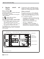
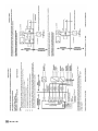
Design and principle of operation
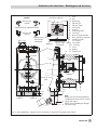
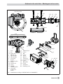
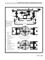
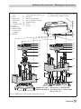
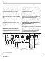
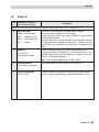
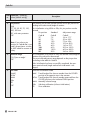
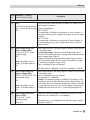
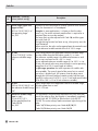
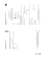
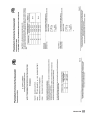
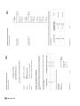
the 4 to 20 mA DC control signal (reference
variable) after it has been converted by the
A/D converter (4). In case of a system deviation, the actuator is either vented or filled
with more air. The supply air is supplied to
the air capacity booster (7) and the pressure
regulator (8). An intermediate flow regulator
(9) with fixed settings is used to purge the
positioner and also guarantees trouble-free
operation of the air capacity booster. The
output signal pressure supplied by the
booster can be limited over the software.
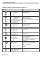
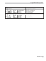
The volume restriction Q (10) is used to optimize the positioner by adapting it to the actuator size.
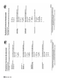
The extended EXPERTplus diagnostics are integrated into the positioner. It provides information on the positioner and generates diagnostic and status alarms, which allow
faults to be pinpointed quickly.
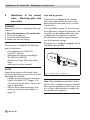
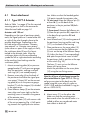
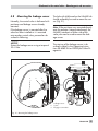
The positioner is suitable for the following
types of attachment using the corresponding
accessories:
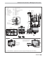
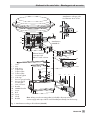
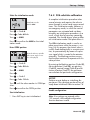
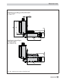
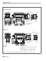
4 Direct attachment to SAMSON
Type 3277 Actuator: Section 4.1
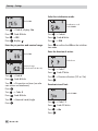
4 Attachment to actuators acc. to
IEC 60534-6 (NAMUR): Section 4.2
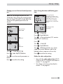
4 Attachment to Type 3510 Micro-flow
Valve: Section 4.4
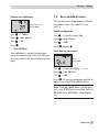
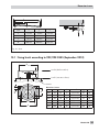
4 Attachment to rotary actuators acc. to
VDI/VDE 3845: Section 4.5
10
EB 8384-2 EN
3.1
Additional equipment
Solenoid valve
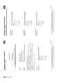
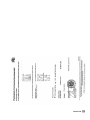
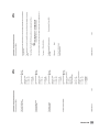
If the operating voltage for the solenoid
valve (12) fails, the supply pressure for the
booster is vented to the atmosphere. Consequently, the actuator is vented and the valve
moves to the fail-safe position.
NOTICE
In manual mode (MAN), the manual set
point is also reset to 0 %. A different manual
set point must be entered again (Code 1).
Position transmitter
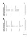
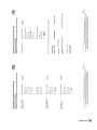
The position transmitter (13) is a two-wire
transmitter and issues the travel sensor signal as a 4 to 20 mA signal processed by the
microcontroller. Since this signal is issued independent of the positioner’s input signal
(min. current 3.8 mA), the actual travel/angle of rotation is controlled in real-time. Additionally, the position transmitter provides
the possibility of signaling a positioner fault
over a signal current of < 2.4 mA or
> 21.6 mA.
Inductive limit switch
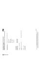
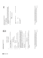
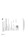
The rotary shaft of the positioner carries an
adjustable tag which actuates the installed
proximity switch. The optional inductive limit
switch (11) is connected to A1, while the
remaining software limit switch is connected
to A2.