1
Electrical connection
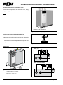
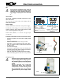
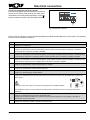
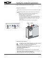
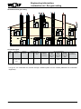
Connection output A1 (230 V AC; 200 VA)
Insert the cable glands into the terminal box. Insert and
secure the connecting cable through the cable gland.
Terminate the connecting cable at terminals L1, N and .
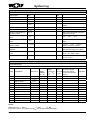
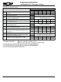
The parameters for output A1 are described in the table.
Fig.: Connection output A1
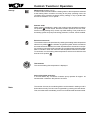
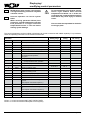
The functions of output A1 can be scanned and adjusted with eBUS-enabled Wolf control accessories. The following
functions can be allocated to output A1:
Code
Explanation
0
No function
Output A1 is not switched
1
DHW circulation pump 100%
Output A1 is switched by control accessory (BM) if DHW circulation has been enabled. Output A1 is constantly
activated when no accessory controller is installed.
2
DHW circulation pump 50%
Output A1 is switched by control accessories (BM) in cycles if DHW circulation has been enabled. 5 minutes ON and
5 minutes OFF. Output A1 is constantly cycled in 5 minute intervals when no accessory controller is installed.
3
DHW circulation pump 20%
Output A1 is switched by control accessories (BM) in cycles if DHW circulation has been enabled. 2 minutes ON and
8 minutes OFF. Output A1 cycles constantly when no accessory controller is installed.
4
Alarm output
Output A1 is switched after a fault and after expiry of 4 minutes.
5
Flame detector
Output A1 is switched after a flame has been detected.
6
3-way valve
Output A1 is switched during cylinder heating.
7
Ventilation damper
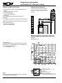
Output A1 is switched first prior to each burner start. The burner will, however, only be enabled after input E1 has
been closed.
Important: In any case, input E1 must also be programmed as "Ventilation damper"
The feedback to input E1 must be made with a floating contact. Otherwise, use an on-site relay for potential
separation.
8
External ventilation
Output A1 is switched inverse to the gas combination valve.
Switching OFF external ventilation (e.g. extractor fan) during burner operation is only required, if the boiler is
operated as an open flue system.
9
External gas valve
Output A1 is switched in parallel to the gas combination valve.
3062880_201305
21