1
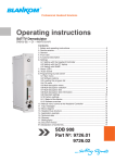
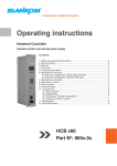
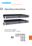
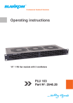
BEB
x00
Part N : 904x.0x
Bus Extender
with 8A-power supply
o
4. Front view
BEB 200
BEB 300
(X3)
(X2)
(X1)
8
3
ADDRESSING SPACE
INPUT VOLTAGE (DC)
INPUT POWER
ADDRESSING SPACE
OUTPUT (DC)
15 UNITS
36...72 V
max. 110 W
15 UNITS
12 V, max. 8 A
BUS EXTENDER
POWER SUPPLY
Type: BEB 200
Part No.: 9047.01
BUS EXTENDER
POWER SUPPLY
Type: BEB 300
Part No.: 9048.02
INPUT VOLTAGE (AC)
INPUT FREQUENCY
INPUT POWER
ADDRESSING SPACE
OUTPUT (DC)
INPUT VOLTAGE (DC)
INPUT POWER
ADDRESSING SPACE
OUTPUT (DC)
100 ... 240V
50/ 60
Hz
max. 110 W
15
UNITS
12 V,
max. 8A
36 ... 72
max. 110
max. 15
12 V, V
W
UNITS
max. 8A
Operating voltage/
control bus
LED „ERROR“ (red)
LED „READY“ (green)
LED „DATA“ (yellow)
Address selection
+
Power supply
_
DC
INPUT
48 V- / max. 3.3 A
+ -
5. Functional description
The Bus Extender BEB x00 is the necessary extension module for the head end bus system. It is equipped with 3 bus connection
sockets. The sockets X1 and X3 are equivalently occupied and are serving the vertical bus extension. The X2 socket of the BEB x00 is
responsible for power supply of signal processing units (modules) within the respective line. It also defines the address of the line and
canalizes the data transfer (see chapter 6). The total power consumption of the respective line (all connected modules within one line)
may not exceed the current limit of the BEB x00. The ADDR. switch position “0” is switching the BEB x00 into redundancy operation
status. Two BEB x00 will be switched parallely. The left/ first (ADDR.= 1...15) canalizes the data transfer, the right/ second BEB x00
(ADDR.= 0) suplies current/ power. The left/ first BEB x00 overtakes the power supply of the respective line in case of a failure (see
chapter 7)
One address is made up of two parts. The fist address-part will be allocated with the address selection switch of the BEB x00 for the
total line (01/ xx ... 15/ xx) and indicates the address of the respective line, the second part will be allocated with the address selection
switch at the connected modules (xx/ 00 .. xx/ 15) and indicates the address of the respective module within the line. (see chapter 8)
Module
ADDR. 15
Module
ADDR. 15
Module
ADDR. 15
Module
ADDR. 01
Module
ADDR. 01
BEB x00
ADDR. 01
Module
ADDR. 01
Module
signal processing
unit
BEB x00
ADDR. 02
BEB x00
Bus Extender
BEB x00
ADDR. 15
HCB x00
Headend
Controller
HCB x00
6. Head end bus structure
The number of the possible module connections (01 ... 15) to a
BEB x00 depends on the total power consumption of this line!
4