1
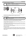
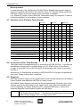
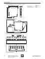
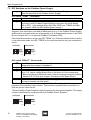
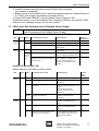
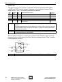
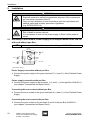
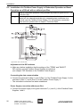
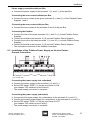
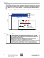
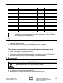
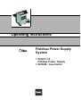
Designated Use
4.1 Exemplary Assembly of a Segment
)
Length segment = Length trunk + ∑ Length spurs ( 1900 m
For information on calculating the allowed segment, trunk and spur lengths,
please refer to IEC 61158-2 and FF AG-181, Rev 3.1.
Fieldbus
Power
Supply
Host
Terminator
Trunk, non-Ex
< 120 m
Trunk, non-Ex
Trunk, non-Ex
<1m
Terminator
Host
redundant
Fieldbus
Power
Supply
redundant
Ex i Field Device
Coupler
Ex i Field Device
Coupler
Ex i / FISCO
Spurs < 120 m
Ex i / FISCO
Spurs < 120 m
...
1
...
Ex i / FISCO
Field Devices
...
...
4/8
1
...
4/8
Ex i / FISCO
Field Devices
14126E02
The Fieldbus Power Supply is connected to the host via the main line. This can be
followed by connecting suitable field device couplers via the trunk.
4.2 Operating Modes
)
Boost operation is only possible by means of the Fieldbus Power Supplies
9412/0.-310 und 9412/0.-320.
Simplex operation
In simplex operation, one Fieldbus Power Supply supplies one segment with energy. The
power supply of the Fieldbus Power Supply may take place redundantly.
In case of overload or short-circuit of the Fieldbus Power Supply or of the trunk, an error
message is output via a relay contact.
In overload mode, normal operation of the FPS continues up to about 540 mA. When the
current output exceeds about 540 mA, the segment is switched off, in order to protect the
connected field devices and the FPS.
From a current output of > about 540 mA, an error message is output via the integrated
relay contact, and the segment is switched off.
Redundant operation
In redundant operation, two Fieldbus Power Supplies supply a segment in parallel with
up to 500 mA. In case of a failure of one Fieldbus Power Supply, the other Fieldbus Power
Supply automatically provides the full power supply, and an error message is output via
a relay contact.
200744 / 941260310030
2010-07-29·BA00·III·en·02
2013-08-19·BA00·III·en·03
Fieldbus Power Supply System
9412/0.-3.0 Fieldbus Power Supply,
9419/08... bus-Carrier
5