1
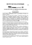
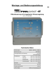
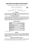
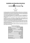
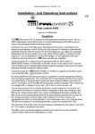
Installation- and Operating Instructions
PC-400-ES
Art.No.3002700105
Functioning:
The
-filter control system PC-400-ES enables time-controlled connection and disconnection of a 400V A.C.
filter pump. Setting of the daytime and the individual response times can be noted from the corresponding
operating instructions of the automatic switch which is enclosed. By means of the selector switch in the front cover
it is possible to:
a)
switch on and off the functioning of the unit. Attention, the control system is thus not disconnected from
the mains supply at all poles!
b) switch the unit to permanent operation or automatic operation (automatic switch) of the filter pump.
Also during the working time of the filter pump, the heating of the pool is regulated by the plug-in electronic
temperature control. During interruptions of the filtering process, the heating is automatically switched off by the
internal locking device. A connection facility for a safety temperature limiter of a flow governor ensures additional
protection of the heating against overheating. The requested temperature of the pool water may be chosen or the
heating may be switched off by an adjuster on the front plate.
Connection terminals for an electronic level control
-NR-12-TRS-2 (Art.No. 3030000020) ensure a comfortable
automatic control of the water level in the pool. Additionally, the filter pump is protected against damage which may
arise due to operation of the filter unit without water.
Connection terminals for an
-EUROTRONIK-1 (potential-free model, Art.No. 3104800200) ensure an
enlargement of the filter control to an automatic filter- and re-flushing control.
A further terminal connection enables the connection of supplementary instruments, e.g. dosage system. The
terminals D/D are potential-free and can therefore be individually used. During the filtering times, the relay point
between the terminals D/D is closed, out of the filtering times, this relay contact point is open. This contact can be
loaded with a tension of a maximum of 230V and a power of a maximum of 400W (cos ϕ=1).
The connection terminals for the winding earthing contact (WSK ‘Wicklungsschutzkontakt’) ensure connection of a
winding earthed switch which is integrated in the motor winding of the filter pump. If this contact opens, e.g. due to
excessive heating of the motor winding, the filter pump and automatically the heating and dosage system are
switched off. As soon as the winding earthing contact closes after cooling-down of the motor winding, the units are
automatically re-activated. Manual re-setting is not necessary. The connection terminals „WSK“ are supplied with
230V.
Operation of the filter pump and the heating are displayed by the control lamps in the front cover - thus, a control is
possible at any time.
The filter pump is protected against overloading by a plug-in electronic protective motor switch (power supply can
be continuously adjusted up to 8A).
Operating instructions PC-400-ES
Page: 2
Technical Data:
Dimensions:
220mm x 219mm x 100mm
Operating voltage:
400V/50Hz
Power consumption of the control system:
Capacity:
Pump:
Heating:
Additional output:
abt.1,5VA
max. 3,0 kW (AC3)
max. 0,4 kW (AC1)
max. 0,4 kW (AC1)
Type of protection:
IP 40
Installation:
For installation, the control unit has to be protected against humidity, according to its type of protection. The power
supply of the unit has to be effected by an all-pole main switch with a contact gap width of a minimum of 3mm.
Before opening the housing, the unit has to be switched free of electrical tension by all means.
Electrical connection:
The electrical connection as well as alignment- and service works shall only be carried out by a qualified
specialist electrician! The following cable arrangement and the corresponding safety instructions in force
shall be observed .
For use of a 400V threephase pump:
For use of a 230V A.C. pump:
Operating instructions PC-400-ES
Page: 3
The bridge which is installed by the manufacturer between the two terminals designated as Th has to be removed if
a safety temperature limiter is connected. If the latter is not connected, the bridge has to remain in place.
The bridge which is installed by the manufacturer between the terminals 13 and 14 has to be removed if a level
control unit NR-12-TRS-2 is connected. If a level control unit is not connected, the bridge has to remain bolted
between these terminals. In this case, the terminals 11 and 12 shall not be used.
The bridge which is installed by the manufacturer between the terminals 3 and 5 has to be removed, if an
EUROTRONIK-1 is connected. If an EUROTRONIK-1 is not connected, the bridge between these terminals has to
remain in place. In this case, the terminals 2 and 4 shall not be used. Attention: Only the EUROTRONIK-1
potential-free model (from 1994 on) shall be used!
The bridge which is installed by the manufacturer between the terminals designated as WSK has to be removed
when connecting the winding earthing contact. If this contact is not connected, it has to remain in place.
Opening of one of the contacts between the terminals 13 and 14 or 3 and 5 involves an immediate disconnection of
the filter pump, the dosage system and the heating.
Closing of one of the contacts between the terminals 2 and 4 or 11 and 12 involves a forced connection of the filter
pump.
The electronic control together with the EUROTRONIK-1, the heating and the level control system are protected by
a 3,15A fine-wire-fuse inside the unit.
Electronic motor protection:
heating
filtering
disturbance
The threephase filter pump is protected against overloading by a plug-in
electronic motor protection. For this purpose, the motor protection has to be set
to the nominal current of the filter pump (see type plate of the pump). If the
nominal current of the filter pump is not known, the motor protection can be set
according to the following procedure:
1. Turn adjusting screw of the motor protection clockwise to the stop point.
2. Switch on the pump.
unlocking
3. Turn adjusting screw slowly anticlockwise until the motor protection is
triggered and the red trouble signal is flashing.
adjustment
0-8 Ampere
4. Turn adjusting screw by a few angular degrees (abt. 10%) clockwise.
5. Unlock motor protection by the black key - trouble signal goes out and the
filter pump is running.
Please see overleaf.
Operating instructions PC-400-ES
Page: 4
Temperature Control:
The plug-in electronic temperature governor and the temperature sensor are matched and should only both be
replaced in case of repair. If, however, a sensor or temperature governor are individually replaced, a new alignment
has to be carried out by a potentiometer on the insert card. If, due to an unfavourable location of the temperature
sensor, the water temperature does not correspond to the requested temperature, it can be re-aligned by the same
potentiometer.
do not adjust!
sensor adjustment
In the standard version, the temperature sensor is available with a line length of 1m. If required, it can be prolonged
up to a maximum of 20m with a shielded line (cross section min. 0.34mm²). The shielding has to be connected to
the terminal 15. Installation of the sensor line near supply mains has to be avoided to rule out possible disturbing
influences.
Since an exact temperature control can only be ensured if there is a
smooth heat transmission between the temperature sensor and the pool
water, an osf immersion shell R 1/2 " (Art.No.3200200001) has to be
installed in the piping system.
We wish you much joy and recreation in your pool.
Subject to change without notice!
November 07