1
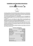
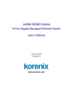
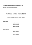
Installation- and Operating Instructions
-2000
Filter Control 400V
Item no. 3100000400
Function:
The
filter control PC-2000 enables a time-dependent switching on and –off of a 400V
three-phase current filter pump by using a freely programmable daily or weekly programme.
The filter control can be remote controlled by an external control element.
While the filter pump is operating the heating of the pool is controlled by the electronic
temperature control. During the filter pauses the heating is automatically switched off by the
internal locking. Due to the given possibility to connect a safety temperature limiter or a flow
monitor, the heating is additionally protected against overheating. On the front plate the
requested temperature of the pool water can be selected or the heating can be switched
off. For the connection of the heating both a living contact (clamp U2) and a floating contact
(clamps 19+20) are available. For the solar collector operation there are terminal clamps
for a
solar actuator available.
Terminal clamps for an electronic level control NR-12-TRS-2 (item no. 3030075020) enable
a comfortable and automatic control of the water level in the pool. Additional terminal
clamps allow to connect a flow monitor or a press key. Thus the filter pump is additionally
protected against damages caused by an operation of the filter system without water.
-EUROTRONIK-10 enable an upgrade of the filter control to an
Terminal clamps for a
automatic filter- and backwash control.
Additional terminal connectors allow to connect accessory devices, e.g. underwater
floodlights and dosing equipment. A consumer (230V/max. 3A) connected to clamp U4 may
optionally be switched on and –off with a key placed in the front lid. The clamp U3 only
drives 230V during the filter periods, outside the filter periods it is floating. The clamps 21
+22 are floating and thus can be individually used. During the filter periods the relay contact
between the clamps 21 and 22 is closed, out off the filter periods this relay contact is open.
This contact can be charged with a maximum voltage of up to 230V and a force of up to
maximum 400 W (cos ϕ=1). Optionally the clamps 21 + 22 can be used to connect a
collective error signal.
The terminal clamps for the protective winding contact allow to connect a protective winding
contact switch that is integrated in the motor winding of the filter pump. If this contact
opens, e.g. due to overheating of the motor winding, both the filter pump and the heating
and dosing equipment will automatically be switched off. As soon as the winding protective
contact closes after cooling of the motor winding, the aggregates will be switched on again
automatically. A manual reset is not necessary. The terminal clamps for the protective
winding contact are charged with 230V.
Terminal clamps for a remote switch enable a remote control of the filter system.
Installation- and Operating Instructions
filter control PC-2000
page: 2 (22)
The operation of filter pump and heating is indicated by pilot lights in the front lid – so a
check is possible at any time.
The filter pump is protected against overload by an electronic motor protection (current
range continuously adjustable up to 8A).
Technical Specifications:
Dimensions:
325mm x 280mm x 160mm
Operating voltage:
400V/50Hz
Power consumption of the control unit:
Breaking capacity:
approx. 10VA
Pump:
max. 3.0 kW (AC3)
Heating:
max. 0.4 kW (AC1)
Dosing equipment:
max. 0.4 kW (AC1)
Additional output:
max. 3A (AC1)
Protection type:
IP 40
Installation:
The control unit has to be installed humidity protected, depending on its protection type.
The power supply of the device has to be effected by an all-pole main switch having a
contact of opening of at least 3mm and a earth leakage circuit breaker with IFN≤ 30mA.
Before opening the housing it is absolutely necessary to switch the device to zero
potential.
Electrical connection:
The electrical connection as well as any adjustment and service work may only be
carried out by an accredited electrical specialist! The enclosed connecting diagrams
and the prevailing corresponding safety regulations are to be observed.
Mains supply for use of a 400V-three-phase current pump:
Pool control PC-2000
17 18 15 16 W1 V1 U1 L3 L2 L1 N
M
Protective
winding
3
Filter pump
400V max. 8A
Pre-fuses
max. B16A
FI-switch
25A/0,03A
Mains 3/N/
400/230V 50Hz
The factory-provided inserted bridge between the clamps 15 and 16 has to be removed if a
pump with protective winding contact is connected. If no connection is carried out, it has to
be remained screwed in. The clamps drive mains voltage!
Instead of the bridge inserted between the clamps 17 and 18 it is possible to connect a flow
monitor or a pressure controller, to additionally protect the pump against dry run. In the filter
Installation- and Operating Instructions
filter control PC-2000
page: 3 (22)
operation this contact has to be closed at the latest 10 seconds after the filter pump has
started, otherwise the filter pump will is switched off and the error signal light flashes. In
the backwash operation this contact is not interrogated. The clamps drive mains voltage!
Mains supply for use of a 230V three-phase current pump:
Pool control PC-2000
17 18 15 16 W1V1 U1 N
Protective
winding
M
1
Filter pump
230V max. 8A
L3 L2 L1 N
Pre-fuses
max. B16A
FI-switch
25A/0,03A
Mains 1/N/
230V 50Hz
The factory-provided inserted bridge between the clamps 15 and 16 has to be removed if a
pump with protective winding contact is connected. If no connection is carried out, it has to
remain screwed in. The clamps drive mains voltage!
Instead of the factory-provided bridge inserted between the clamps 17 and 18 it is possible
to connect a flow monitor or a pressure controller. In the filter operation this contact has to
be closed at the latest 10 seconds after the filter pump has started; otherwise the filter
pump is switched off and the error signal light flashes. This contact is not interrogated in
the backwash operation. The clamps drive mains voltage!
So that the electronic motor protection operates properly, the motor current has to be led
via all 3 contact points of the filter control (clamps L2 and L3 as well as U1 and V1 bridged,
pump connected to W1).
Installation- and Operating Instructions
filter control PC-2000
page: 4 (22)
Connection of the heating:
Filter control PC-2000
N U5 U6
23 24 U2 N 19 20
Safety
temperature
limiter
Heating 230V
max. 400W
Heating
floating
max. 4A
N 6 2
Solar
actuator 230V
The factory-provided inserted bridge between the clamps 23 and 24 has to be removed if a
safety temperature limiter is connected. If no connection is carried out, it has to remain
screwed in. The clamps drive mains voltage! If the contact of the safety temperature limiter
opens, the heating is switched off at clamp U2. The floating relay contact between the
clamps 19 and 20 is not influenced by the safety temperature limiter. On dimensioning the
safety device you have to take into consideration that the current of the heating flows via
the clamps 23 and 24.
For the operation of the solar heating it is possible to connect a 230V
-solar actuator to
the clamps U5 and U6. When solar operated the clamp U6 drives mains voltage and clamp
U5 is floating. If the solar heating is not operated, clamps U6 is floating and clamp U5 leads
mains voltage.
Level control and backwash control:
Filter control PC-2000
L1 N 2 3 4 5
L1 N 11 12 13 14
L1 N 2 3 4 5
L1 N 11 12 13 14
Backwash control
EUROTRONIK-10
Water level control
NR-12-TRS-2
The factory-provided inserted bridge between the clamps 13 and 14 has to be removed if a
level control NR-12-TRS-2 is connected. If no level control is connected, the bridge has to
remain screwed in between these clamps. In this case the clamps 11 and 12 remain
unused. The clamps drive mains voltage!
Installation- and Operating Instructions
filter control PC-2000
page: 5 (22)
The factory-provided inserted bridge between the clamps 3 and 5 has to be removed if a
EUROTRONIK-10 is connected. If no EUROTRONIK-10 is connected, the bridge between
these clamps has to remain screwed in. In this case the clamps 2 and 4 remain unused.
The clamps drive mains voltage!
An opening of one of the contacts between the clamps 13 and 14 or 3 and 5 causes an
immediate switching off of the filter pump, the dosing equipment and the heating.
Closing of one of the contacts between the clamps 2 and 4 or 11 and 12 causes an
emergency switching on of the filter pump whereas the heating and the dosing equipment
remain switched off.
Additional connecting possibilities:
Filter control PC-2000
U4 N
L1 N
Addit. device
230V max.3A
U3 N
L1 N
Dosing equip.
230V max.3A
21 22
Dosing equip. or
error signal
(floating)
7 8 9 10
Pump
Pump
OFF
ON
Remote switch or
pool covering
A 230V accessory device (e.g. underwater floodlight) can be connected to clamp U4, this
device can be optionally switched on and –off with a key in the front lid (or in the external
control element).
A 230V accessory device (e.g. dosing equipment) can be connected to the clamp U3 and
during filter operation it can be switched on together with the filter pump.
Between the clamps 21 and 22 there is a floating relay contact in the control unit. This can
optionally be used:
• for the control of additional dosing equipment (in this case it is closed during filter
operation),
• to serve as a collective error signal (then it is closed in case of defects).
This contact can be charged with a maximum of 230V/4A.
A remote switch or the pool covering can be connected to the clamps 7, 8, 9 and 10. These
clamps drive mains voltage!
An opening of the contact between the clamps 9 and 10 causes an immediate switching off
of the filter pump, the dosing equipment and the heating.
A closing of the contact between the clamps 7 and 8 causes the filter system being
switched on.
Installation- and Operating Instructions
filter control PC-2000
page: 6 (22)
Temperature sensor:
-Immersion sleeve
Filter control PC-2000
31 32
33 34
Temperature
sensor pool
Solar
sensor
The pool temperature sensor is connected to the clamps 31 and 32. As a standard the
temperature sensor is delivered with a cable length of 1.5m. If required, this can be
lengthened with a two-core cable (cross section min. 0.5mm²) up to a maximum of 20m. It
should be avoided to lay the sensor cable near power lines to exclude possible
disturbance.
As an exact temperature control is only possible with a good heat transfer between
temperature sensor and pool water, you have to install a
-immersion sleeve R 1/2 "
(item no. 3200200003) into the piping system.
Any polarity of the sensors is possible.
Additionally a solar temperature sensor (item no. 3100000030) can be connected to the
clamps 33 and 34. As a standard the temperature sensor is delivered with a cable length of
20m. I required, it may be lengthened with a two-core cable (cross section min. 0.5mm²) up
to a maximum of 50m. It should be avoided to lay the sensor cable near power lines to
exclude possible disturbance. The solar temperature sensor has to be installed at the
output of the solar collector and must have a good thermal contact to the back-flowing
water.
External control panel:
Filter control PC-2000
35 36 37 38
35 36 37 38
External control element
An external control panel may be connected in-wall
(item no. 3100000420) or on-wall (item no.
3100000410) to the clamps 35-38. A four-core
telephone cable (item no. 3100000500) with a length
of maximum 50m is used for the connection to the
filter control. It should be avoided to lay the
connecting cable near power lines to exclude
possible disturbance.
Installation- and Operating Instructions
filter control PC-2000
page: 7 (22)
Control elements on the front plate:
Control ON/OFF
Pilot light additional heating
Manual operation
Pilot light solar heating
Acknowledge error signal
Pilot light filter pump
Additional output ON/OFF
Adjusting keys
Select temperature
LCD display
Program timer
Set time
Normal operation display with current water temperature
and time.
LCD
23,4 °C
LCD
23,4 °C subsequent run The filter pump temporarily continues to run after the
heating has been switched off.
LCD
forced start
13:37
The filter pump has been switched on by the backwash
control EUROTRONIK or the level control NR-12-TRS-2.
LCD
pump locked
13:37
The filter pump has been switched of by the backwash
control EUROTRONIK, the level control NR-12-TRS-2, by
a remote switch connected to the clamps 9 and 10 or by
the protective winding contact.
14:46
LCD
pump overloaded!
The filter pump has been switched of by the electronic
motor protection. To switch on the pump again, the key
must be pressed after the pump has cooled.
LCD
pump doesn't deliver
The filter pump has been switched off by the press key
connected to the clamps 17 and 18 or by the flow monitor.
To switch the pump on again, the key
must be pressed
after the error has been cleared.
LCD
mains phase missing!
The filter pump has been switched off because there is no
current in all 3 phases of the three-phase supply network.
must be pressed
To switch the pump on again, the key
after the error has been cleared.
LCD
sensor defect
The temperature control is out of operation because the
temperature sensor is not connected or is defect.
13:37
Control ON/OFF
Manual operation
Acknowledge
error signal
With this key the complete control can be switched on and –
off. Attention! By doing so, the control is not switched to zero
potential. If the control is switched on, this key flashes.
With this key the filter pump can be manually switched on,
independently from the timer. The key flashes with manual
operation.
If the control detects an error (e.g. motor protection) this key
will flash in red. This error signal must be acknowledged with
this key, so that the normal operation of the equipment can be
Installation- and Operating Instructions
filter control PC-2000
page: 8 (22)
continued.
Additional output With this key an additional output (clamp U4, 230V) is
controlled, that can for instance be used to switch an
ON/OFF
underwater floodlight. The key flashes with consumer switched
on. The function of the additional output is not interconnected
with the filter pump.
Pilot light pump
This pilot light indicates the operation of the filter pump.
This pilot light flashes if the additional heating is switched on.
Pilot light
additional heating
Pilot light
heating
Select
temperature
solar This pilot light flashes if the solar heating is operated.
With this key the temperature of the pool water is selected:
1. Press
key ⇒ the display shows
23,4 ° set temperature
2. With the keys
and
the requested temperature within a
range of 0.1°C and 40°C can be selected now.
3. If the heating is to be completely switched off, you have to
as long as the
reduce the temperature with the key
heating off
display indicates
.
4. To save the requested temperature, press the key
again.
If on setting the temperature no key is pressed for more
than 10 seconds, the last selected temperature is
automatically saved and the normal operation display
appears again.
5. If a solar sensor has been connected to the control, the
current temperature of the solar sensor can be displayed
with this key:
key twice ⇒ the display indicates the temperature
6. Press
at the solar sensor, e.g. 32,8 ° solar sensor .
again. If no key is pressed
7. To close this display press the
for more than a minute, the normal operation display
appears automatically.
Setting time
With this key the current time is set:
14:26
1. Press
key ⇒ the display indicates time:
. If the
timer is operated as a weekly timer, the corresponding day
of the week is also displayed.
2. With the keys
and
you can now set the current time.
3. To save the time, press the
key again. If on setting no
key is pressed for more than 10 seconds the last displayed
time is automatically saved and the normal operation
display appears again.
Installation- and Operating Instructions
Programming
timer
filter control PC-2000
page: 9 (22)
of With this key the built-in timer is programmed; for this you
always have to enter the switch on time and the corresponding
switch off time in pairs:
--:-1. Press
. If the
key ⇒ the display indicates 1. pump on:
timer is operated as a weekly timer, the corresponding day
of the week is also displayed.
2. Now you can set the requested switch on time with the keys
and .
3. Press
key again ⇒ the display indicates
1. pump off:
0:00
4. Now the requested switch off time can be set with the keys
and .
5. Press
key again ⇒ the display indicates
2. pump of:
--:--
6. Now additional switching times can be programmed as
described under points 2-5.
7. To save the switching times, press the
again. If on
setting no key is pressed for more than 10 seconds the last
displayed switching time is automatically saved and the
normal operation display appears again.
If some switching times have already been programmed, these
key:
may be deleted with the
1. Press
key as long as the switching time, that is to be
deleted, is displayed 2. pump on 8:25
2. With the keys
2. pump on:
--:--
and
set the switch on time to
(between 23:59 and 0:00).
again – the
3. To delete the switch on time, press the key
corresponding switch off time is also automatically deleted.
+
Adjusting
keys
With these keys you can program the water temperature, the
time and the switching times.
Adjustment of the temperature control:
The electronic temperature control and the temperature
Sensor adjustmentsensor have been matched factory-provided. If one of the
sensors is exchanged or if a sensor cable is lengthened, you
have to carry out a new adjustment with the potentiometers
in the control unit, if necessary. A clockwise turning of the
Water
Solar
potentiometer causes an increase of the displayed water
temperature. If the potentiometer for solar sensor is turned
clockwise, a higher collector temperature is displayed. As
the solar temperature control only works properly with
precisely adjusted sensors, this adjustment should only be
carried out by a trained service technician.
Installation- and Operating Instructions
filter control PC-2000
page: 10 (22)
Fuses:
T2A control
T800mA
external control element
The
electronic
control
is
protected by a 2A micro-fuse on
the circuit board inside the
device. There is each one 3.15A
micro-fuse available for the
heating, the dosing equipment
and for the additional output.
The short-circuit protection for
the filter pump has to be
ensured by customer provided
pre-fuses of max. 16A.
T3,15A Additional output
T3,15A Dosing equipment
T3,15A Heating
Electronic motor protection:
Motor protection
0A
8A
31 32 33 34
The three-phase current filter pump is protected against
overload by an electronic motor protection. For this the
motor protection has to be adjusted to the nominal current of
the filter pump (see type plate of the pump). The adjusting
controller for the motor protection is placed in the clamping
box to protect it against inadvertent adjustment. If the
nominal current of the filter pump is not known, the motor
protection can be adjusted according to the following
process:
1. Turn adjusting screw of the motor protection to the right
stop.
2. Switch on pump.
3. Turn adjusting screw slowly anti-clockwise as long as the
motor protection is triggered and the red error signal
flashes.
4. Turn adjusting screw clockwise by some angular degrees
(approx. 10%).
Unlock the motor protection with the
key – the error signal
stops flashing and the filter pump runs.
Coding switch:
For a universal use of the filter control PC-2000 for various
filter systems, there is a coding switch available on the
circuit board that can be used to set various operating
modes. The following functions can be set:
Coding switch
Installation- and Operating Instructions
DIP
1
ON
2 3
4
DIP
1
ON
2 3
4
Daily timer
Weekly timer
1 2 3 4
DIP
DIP
1
ON
2
3
4
Priority circuit of
the solar heating
DIP
1
ON
2 3
4
Clamps 21 + 22
dosing equipment
1
ON
2 3
4
no priority circuit of
solar1heating
2 3 4
DIP
1
ON
2 3
4
Clamps 21 + 22
error
signal
1 2 3
4
filter control PC-2000
page: 11 (22)
Daily or weekly timer:
With coding switch 1 you can choose if the built-in timer
should use the same filter periods each day (daily timer), or
if the filter periods are programmed for each single day of
the week (weekly timer). In the position OFF (lower
switching position) it operates as a daily timer, in the
position ON (top switching position) as a weekly timer.
Priority circuit of the solar heating:
With coding switch 2 you can activate a priority circuit of the
solar heating. In the position ON (top switching position) the
solar heating is only operated during the filter periods. In
the position OFF (lower switching position) the solar
temperature control is also operated off the filter periods so
that the solar power can also be used off the set filter
periods.
Collective error signal:
The function of the relay contact between the clamps 21
and 22 can be switched over with coding switch 3:
In the position OFF (lower switching position) the contact is
closed during the filter operation and can, e.g. be used to
operate a dosing equipment. In the position ON (top
switching position) this contact is closed in case of an error
(motor protection, flow monitor or break of sensor).
DIP
1
ON
2 3
4
no
priority circuit
DIP
DIP
1
ON
ON
2 3
4
Priority circuit
of1 the
2 3heating
4
Priority circuit of the additional heating:
With the coding switch 4 you can activate a priority circuit of
the temperature control. In the position OFF (lower
switching position) the heating is only operated during the
filter periods. In the position ON (top switching position) the
temperature control is also in operation off the filter periods,
so that the heating and the filter pump are automatically
switched on at any time, if the temperature falls below the
set value.
On delivery all 4 coding switches are in OFF position.
Installation- and Operating Instructions
filter control PC-2000
page: 12 (22)
Service terminal:
Connector for
Service-Terminal
For an optimum adjustment of the control to the various pool
equipment’s as well as to facilitate the installation and the
error detection, an osf service terminal (item no.
3010000900) can be connected to this control unit. The
terminal connector for this is placed on the circuit board
inside the device. Before opening the housing and
plugging of the service terminal it is absolutely
necessary to switch the control to zero potential! In the
display of the service terminal the first 4 lines of a diagnostic
text appear after the control unit has been switched on, e.g.:
filter operation
off
heating
23,0°
water:
38,4°
solar:
Operation mode of the filter system
Operation mode of the heating
measured water temperature
measured collector temperature
Additional lines may be enquired with the keys and . Where required, the values in the
first line may be changed after the
key has been pressed.
1.
Operating mode of the filter system
This line indicates the current mode of the filter system.
Following displays are possible:
Control off
The control has been switched off with the key
Filter system off
The filter system is switched off.
Filter operation
The filter system has been switched on by the timer, the
in the front lid or by the remote switch.
manual switch
.
Subsequent running After the heating has been switched off the filter pump
continues to run.
time
Emergency
switching on
The filter pump has been switched on by the backwash
control EUROTRONIK or the level control NR-12-TRS2.
Priority circuit
The filter pump has been switched on off the set filter
periods by the temperature control because the filter
pump operates priority switched.
Pump locked
The filter pump has been temporarily switched off by the
backwash control EUROTRONIK, the level control NR12-TRS-2, the remote switch or by the protective
winding contact.
Motor protection
The filter pump has been switched off because the
electronic motor protection has triggered.
Press key
The filter pump has been switched off because a press
key connected to the clamps 17 and 18 or a flow
monitor have not started on time after the filter pump
has been switched on.
Installation- and Operating Instructions
Net phase missing
2.
filter control PC-2000
page: 13 (22)
The filter pump has been switched off because there is
no current in all 3 net phases.
Operating mode of the heating
This line displays the current operating mode of the temperature control.
The following displays are possible:
3.
Controller off
The heating has been switched off with the adjusting
keys in the front lid.
Heating off
The heating has been switched off outside the filter
periods.
Heating locked
The heating is locked because there is a priority circuit
of the EUROTRONIK or the level control NR-12-TRS-2,
or because the filter pump has been switched off due to
an error condition.
Temp. reached
The heating has been switched off because the set
nominal temperature has been reached.
Heating on
The heating is switched on because the water
temperature is below the set nominal temperature.
Solar heating on
The solar heating is switched on because the water
temperature is below the set nominal temperature and
because the collector is warmer than the pool water.
Water temperature
In this line the current water temperature is indicated. If this display does not match
the actual temperature it can be readjusted with the adjusting controller on the circuit
board (see section temperature control). A clockwise turning of the adjusting
controller causes an increase of the displayed value. In case of a defect temperature
sensor “break of sensor” is displayed. Attention: In case of both temperature
sensors having the same temperature, the solar sensor must not display
higher values than the water temperature sensor, as otherwise the solar
heating will not switch off.
4.
Solar temperature
This line indicates the current collector temperature. If the display does not match
the actual temperature, it can be readjusted with the adjusting controller on the
circuit board (see section temperature control). A clockwise turning of the adjusting
controller thus causes an increase of the displayed value. In case of a defect
temperature sensor "-----" is displayed. Attention: In case of both temperature
sensors having the same temperature the solar sensor must not display higher
values than the water temperature sensor, as otherwise the solar heating will
not switch off.
5.
Nominal temperature
In this line the nominal temperature that has been set with the
in the front lid is
displayed. If the temperature control has been switched off, „no heating“ is
displayed.
Installation- and Operating Instructions
filter control PC-2000
page: 14 (22)
6.-8. Motor current
This line indicates the current power consumption of the filter pump in the 3 phases
of the three-phase supply network.
9.
Motor protection
This line indicates the current set release current of the electronic motor protection.
10.
Solar difference
This line shows the amount the solar collector has to be warmer than the pool water,
before the solar heating is switched on.
Solar heating off
collektor temperature
Solar
difference
Solar
difference
Solar h.on
Solar heating off
water temperature
Solar h. on
This value can be matched to the requirements of each corresponding solar
equipment, if it is displayed in the first line of the service terminal:
1.
On pressing the key
appears:
the filter system is switched off and the following display
solar diff.
3 °
difference temp.
between water
and collector
2. The temperature difference can be changed with the keys
setting value is 0.5°, the largest is 10°.
and
.
The smallest
3. If the key
is pressed again the normal diagnostic display appear and the filter
system continues to operate. The set value is automatically saved.
On delivery the set temperature difference is 3°.
11.
Solar additional temperature
This line indicates the amount that may be exceeded by the set nominal temperature
of the pool with solar heating, so that the insolation is optimally used during the day.
This value may be matched to the corresponding requirements of each pool
equipment, if it is displayed in the first line of the service terminal:
1. The filter system is switched off after pressing the key
appears:
and the following display
solar add.:
5,0 °
overheating of
the water with
solar operation
2. The temperature difference can be changed with the keys
smallest setting value is 0°, the largest is 15°.
and
. The
3. If the key is pressed again the normal diagnostic display appears and the filter
system continues to operate. The set value is automatically saved.
On delivery the set temperature difference is 5°.
Installation- and Operating Instructions
12.
filter control PC-2000
page: 15 (22)
Limit temperature
This line displays the maximum temperature where the solar heating is automatically
switched off for safety reasons, independent of the set nominal value. This value can
be matched to the corresponding requirements of each pool equipment if displayed
in the first line of the service terminal:
1. On pressing the key
appears:
the filter system is switched off and the following display
limit temp.: 40,0 °
max. possible
water temp. with
solar operation
2. The limit temperature can be changed with the keys
setting value is 30°, the largest is 50°.
and
. The smallest
3. If the key
is pressed again the normal diagnostic display appears and the filter
system continues to operate. The set value is automatically saved.
On delivery the set temperature difference is 40°. This limit temperature only has an
effect on the solar heating.
13.
Minimum time of the additional heating
In this line the minimum time where the additional heating is switched on or -off by
the temperature control is indicated to avoid too short switching intervals. This value
can be matched to the corresponding heating equipment if it is displayed in the first
line of the service terminal:
1. On pressing the key
appears:
the filter system is switched off and the following display
min. heating 120 s
min.switching
time of the
heating
and
the minimum time can be changed in steps of 10s. The
2. With the keys
smallest setting value is 10s, the largest is 1800s (30 minutes).
3. If the key
is pressed again the normal diagnostic display appears and the filter
system continues to operate. The set value is automatically saved.
4. The time set here only has an effect on the behaviour of the temperature control.
On switching off the filter pump the additional heating is switched off immediately,
independent from the set waiting time. On delivery a minimum time of 2 minutes is
set.
14.
Minimum time of the solar heating
This line indicates the minimum time where the solar heating is switched on and -off
by the temperature control to avoid too short switching intervals. This value can be
matched to the corresponding solar equipment if it is displayed in first line of the
service terminal:
1. After the key has been pressed, the filter system is switched off and the
following display appears:
min.solar
120 s
min.switching
time of the
solar heating
Installation- and Operating Instructions
filter control PC-2000
page: 16 (22)
2. With the keys
and
the minimum time can be changed in steps of 10s. The
smallest setting value is 10s, the largest is 1800s (30 minutes).
3. If the key is pressed again, the normal diagnostic display appears and the filter
system continues to operate. The set value is automatically saved.
The here set time only has an effect on the behaviour of the temperature control.
On switching off the filter pump the heating will be immediately switched off,
independent from the set waiting time. On delivery a minimum time of 2 minutes is
set.
15.
Subsequent running of the filter pump
In this line it is indicated how long the filter pump continues to run after the additional
heating has been switched off. This value can be matched to the corresponding filter
system, if displayed in the first line of the service terminal:
1. On pressing the key
appears:
the filter system is switched off and the following display
subs.time
10 s
subsequent
running time of
the filter pump
2. With the keys
and
the starting time can be changed. The smallest setting
value is 0s, the largest is 1800s.
3. If the key is pressed again the normal diagnostic display appears and the filter
system continues to operate. The set value is automatically saved.
On delivery the subsequent running time of the filter pump is switched off
(subsequent running time = 0).
16.
Starting time of the filter pump
This line indicates the maximum allowed time of the filter pump as from switching on
until reaching of the normal flow rate. If the contact of a flow monitor connected to
the clamps 17 and 18 or a press key is not closed after switching on within this time,
the filter pump is switched off again and the error signal light flashes. This value can
be matched to the corresponding requirements of each filter equipment, if displayed
in the first line of the service terminal:
1. On pressing the
appears:
key the filter system is switched off and the following display
startup time 10 s
pump startup
time without
flow minotoring
2. With the keys
and
the starting time can be changed. The smallest setting
value is 5s, the largest is 20s.
3. If the key is pressed again the normal diagnostic display appears and the filter
system continues to operate. The set value is automatically saved.
This time is only important in normal filter operation, on backwashing the press key
is not interrogated. On delivery a starting time of 10s is set.
17.
Operating time of pump
This line indicates the total number of operating hours of the filter pump.
Installation- and Operating Instructions
18.
filter control PC-2000
page: 17 (22)
Operating time of heating
This line indicates the total number of operating hours of the additional heating.
19.
Solar operating time
This line indicates the total number of operating hours of the solar heating.
20.
Motor protection counter
This line indicates how often the electronic motor protection has triggered.
21.
Press key counter
This line indicates how often the flow monitor connected to the clamps 17 and 18 or
the press key have triggered.
22.
Phase failure counter
This line indicates how often the pump has been switched off due to net phase
failure.
23.
Backwash counter
This line indicates, how often EUROTRONIK has started a backwash process.
The following lines enable the service technician to check the input signals and the output
relays of the filter control
24.
Emergency switching on of the NR-12-TRS-2:
This line indicates if the level control NR-12-TRS-2 has demanded an emergency
switching on.
The following displays are possible:
25.
Emergency
switching on OFF
No emergency switching on or clamps 11 and 12 not
connected
Emergency
switching on ON
Emergency switching on demanded or clamps 11 and
12 connected
EUROTRONIK backwash signal:
This line indicates if the EUROTRONIK switches on the filter pump while washing
back or rinsing clear.
The following displays are possible:
26.
EUROTRONIK OFF
No switching on command from the EUROTRONIK
EUROTRONIK ON
The EUROTRONIK has switched on the filter pump
Remote switch:
This line indicates if the filter control has been switched on by the remote switch
connected to the clamps 7 and 8.
The following displays are possible:
27.
Remote switch OFF
The remote switch is switched off (contact open)
Remote switch ON
The remote switch is switched on (contact closed)
Flow monitor:
In this line the switching mode of the press key connected to the clamps 17 and 18
or the flow monitor is indicated.
Installation- and Operating Instructions
filter control PC-2000
page: 18 (22)
The following displays are possible:
28.
Flow: OFF
The contact in the flow monitor is open (the pump does
not deliver)
Flow: ON
The contact in the flow monitor is closed (pump delivers)
Locking:
This line indicates if the filter system has been switched off by the EUROTRONIK,
NR-12-TRS-2, the protective winding contact or by a remote switch connected to the
clamps 9 and 10.
The following displays are possible:
29.
Locking OFF
The pump is switched off (one of the contacts is open)
Locking ON
The operation of the pump is released (all locking
contacts are closed)
Operating mode of the timer:
This line indicates if the built-in timer operates as a daily or a weekly timer. The
operating mode of the timer can be chosen with coding switch no.1.
The following displays are possible:
Daily timer
The programmed switching times are the same for each
day
Weekly timer
You can program different switching times for each day
of the week
On delivery the timer operates as a daily timer.
30.
Function of the clamps 21 and 22:
This line indicates if the relay contact between the clamps 21 and 22 serves to
control an additional dosing equipment or if it serves as a collective error signal. The
function of this contact can be switched over with coding switch no. 3.
The following displays are possible:
21 u.22 Dosing
Coding switch no. 3 is in position OFF. The relay contact
is closed if the pump is running in filter operation.
21 u.22 Error
Coding switch no. 3 is in position ON. The relay contact
is closed in case of an error.
On delivery this contact operates to control an additional dosing equipment.
31.
Priority circuit of the heating:
In this line it is indicated if the temperature control takes priority over the setting of
the filter times. In case of priority circuit the filter pump can also be switched on by
the temperature control outside the set filter times. Without priority the temperature
control only operates during the filter periods. The priority circuit can be switched
over with coding switch no. 4.
The following displays are possible:
Priority OFF
Coding switch no. 4 is in position OFF. The additional
heating only operates during the filter periods.
Installation- and Operating Instructions
Priority ON
filter control PC-2000
page: 19 (22)
Coding switch no. 4 is in position ON. The temperature
control also works outside the filter periods. If the water
temperature falls below the set nominal temperature,
the filter pump and the additional heating are
automatically switched on.
On delivery the priority of the additional heating is switched off.
32.
Priority circuit of the solar heating:
In this line it is indicated if the solar heating takes priority over the setting of the filter
times. In case of priority circuit the filter pump may also be switched on by the
temperature control outside the set filter times. Without priority the temperature
control only operates during the filter periods. The priority circuit of the solar heating
can be switched over with coding switch no. 2.
The following displays are possible:
Priority solar OFF
Coding switch no. 2 is in position ON. The solar heating
only operates during the filter periods.
Priority solar ON
Coding switch no. 2 in position OFF. The solar heating
also operates outside the filter periods. In case of
insolation, the filter pump and the solar heating are
automatically switched on.
On delivery the priority of the solar heating is switched on.
The following lines serve the manual control of the output relay.
33.
Filter pump
If the operating mode of the filter pump is displayed in the first line of the service
terminal, the pump can be manually switched on or –off:
1. On pressing the key
appears:
the filter system is switched off and the following display
filter pump: on
pump can be
operated
manually !
the filter pump can be switched on and with the key
it can be
2. With the key
switched off again. Attention! The electronic motor protection is out of
operation in this function!
3. If the key is pressed again the normal diagnostic display appears and the filter
system continues to operate.
34.
Solar operation
If the operating mode of the solar heating is displayed in the first line of the service
terminal, it can be manually switched on or –off:
1. On pressing the key
appears:
the filter system is switched off and the following display
solar system
manual operation
actuator:
off
off
pump:
2. With the key the solar heating can now be switched on and with the key
can be switched off again. After switching on the solar heating the following
it
Installation- and Operating Instructions
filter control PC-2000
page: 20 (22)
display appears:
solar system
manual operation
actuator:
on
off
pump:
3. Now you can additionally switch on the filter pump with the key
. Attention!
The electronic motor protection is out of operation in this function! After the
filter pump has been switched on, the following display appears:
solar system
manual operation
actuator:
on
on
pump:
4. If the key is pressed again the normal diagnostic display appears and the filter
system continues to operate.
35.
Heating
If the operating mode of the heating is indicated in the first line of the service
terminal it can be manually switched on or –off:
1. After pressing the key
appears:
the filter system is switched off and the following display
heating
manual operation
heating:
off
filter pump: off
the additional heating can be switched on and with the key
it
2. With the key
can be switched off again. The filter pump is also automatically switched on.
Attention! The electronic motor protection is out of operation in this
operating mode!
3. If the key is pressed again the normal diagnostic display appears and the filter
system continues to operate.
36.
Dosing equipment
If the operating mode of the dosing equipment is indicated in the first line of the
service terminal, it can be manually switched on or –off:
1. After pressing the key
appears:
the filter system is switched off and the following display
dosing eqip.
filterpump
on
on
2. With the key
the dosing equipment can be switched on and with the key
it
can be switched off again. The filter pump is also automatically switched on.
Attention! The electronic motor protection is out of operation in this
operating mode!
is pressed again the normal diagnostic display appears and the filter
3. If the key
system continues to operate.
37.
Error signal
If the operating mode of the error signal is indicated in the first line of the service
terminal, it can be manually switched on or –off:
Installation- and Operating Instructions
1. After pressing the key
appears:
filter control PC-2000
page: 21 (22)
the filter system is switched off and the following display
error signal on
manual operation
output is
switched on
2. With the key the collective error signal can be switched on and with the key
it can be switched off again.
3. If the key
is pressed again the normal diagnostic display appears and the filter
system continues to operate.
This function can only be used if the coding switch no. 3 is in ON position.
38.
Additional output
If the operating mode of the additional output is indicated in the first line of the
service terminal, it can be manually switched on or –off:
1. After pressing the key
appears:
the filter system is switched off and the following display
aux. output
off
output can be
operated
manually !
2. With the key the additional output can be switched on and with key
switched off again.
it can be
3. If the key
is pressed again the normal diagnostic display appears and the filter
system continues to operate.
Computer interface:
serielle Schnittstelle
So that you can file the set values and the content of the
operating hour counters with the service terminal, a PC
can be connected to the built-in serial interface by using a
special connecting line. The program that is delivered
together with the connecting line reads out the saved
values in the filter control and represents these in a clear
from on the screen and, if required, saves this data on your
PC.
We wish you a lot of fun and recreation in your swimming pool.
Subject to alteration!
Februar 07
Installation- and Operating Instructions
filter control PC-2000
page: 22 (22)