1
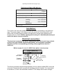
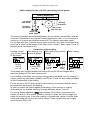
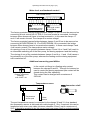
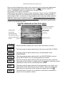
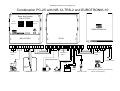
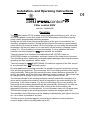
Operating Instructions PC-25 page 1 (10)
Installation- and Operating Instructions
-25
Filter control 400V
Item No. 3100000430
Function:
The
-filter control PC-25 enables a time-dependent switching on and –off of a
400V three-phase current filter pump or a 230V alternating-current filter pump by
using a freely programmable switching program.
During the run time of the filter pump the heating of the pool is controlled by the
electronic temperature control. During the filter pauses the heating is automatically
switched off by the internal locking. On the front plate you can select the requested
temperature for the pool water or you can switch off the heating. A floating contact
(clamp 22 + 23) is available to connect the heating. For the operation with solar
collectors, terminal clamps for a
-solar-actuator are available.
Terminal clamps for a electronic level adjustment NR-12-TRS-2 (item no.
3030075020) enable a comfortable, automatic control of the water level in the pool.
Thus the filter pump is additionally protected against damages, that could arise when
operating the filter equipment without water.
Terminal clamps for a
-EUROTRONIK-10 enable an upgrade of the filter control
to an automatic filter- and backwash control.
By using additional connecting terminals it is possible to connect accessory devices,
such as dosing equipments. The connectors 20+21 are floating and thus they can be
used individually. During the filter periods the relay contact between connectors 20
and 21 are closed, out of the filter times this relay contact is opened. This contact can
be charged with a voltage of up to max. 230 V and a current of max. 4A.
The terminal clamps for the winding protective contact enable the connection of a
micro-switch to protect the winding, which is integrated in the motor winding of the
filter pump. If this contact opens, e.g. due to overheating of the motor winding, the
filter pump and the dosing equipment will be automatically switched off. As soon as
the winding protective contact closes after cooling of the motor winding, the
aggregates will switch on automatically. It is not necessary carry out a manual reset.
The terminal clamps for the winding protective contact are charged with 230V.
The operation of the filter pump and the heating is displayed by pilot lights in the front
lid – so a check is possible at any time.
The filter pump is protected against overload by an electronic motor protection
(current range continuously adjustable up to 8A).
Operating Instructions PC-25 page 2 (10)
Technical Specifications:
Dimensions:
220mm x 219mm x
100mm
Operating voltage:
400V/50Hz
Power consumption of the control:
Breaking capacity:
ca.10VA
Pump:
max. 3,0 kW (AC3)
Heating:
max. 230V/4A
Dosing
equipment:
max. 230V/4A
Protection type:
IP 40
Installation:
The control unit has to be installed humidity protected, depending on its protection
type. The power supply of the device has to be carried out via an all-pole(?) main
switch with a contact opening width of at least 3mm and an earth leakage circuit
breaker with IFN≤ 30mA. Before opening the housing it is absolutely necessary to
switch the device to zero potential.
Electrical connection:
The electrical connection as well as adjustment- and service work may only be
carried out by accredited electrical specialists! The enclosed connecting
diagrams and the corresponding prevailing safety regulations must be
observed.
Mains supply for use of a 400V-three-phase current pump:
Pool-Control-25
N L1 L2 L3
U1 V1
pre-fusing
max. B16A
M
3
FI-switch
25A/0,03A
W1 WSK
winding
protection
filter pump
400V max. 8A
net 3/N/
400/230V 50Hz
The factory-provided inserted bridge between the two clamps called WSK, has to be
removed, if connected with a pump with winding protective contact. If no connection
is carried out, it has to be remained screwed in. The clamps drive mains voltage!
Operating Instructions PC-25 page 3 (10)
Mains supply for use of a 230V-alternating current pump:
Pool-Control-25
N L1 L2 L3
pre-fusing
max. B16A
N U1 V1 W1 WSK
winding
protection
M
1
FI-switch
25A/0,03A
filter pump
230V max. 8A
mains 1/N/
230V 50Hz
The factory-provided inserted bridge between the two clamps named WSK, must be
removed, if connected to a pump with winding protective contact. If no connection is
carried out, it needs to be remained screwed in. The clamps lead mains supply!
For a proper operation of the electronic motor protection, the motor current has to be
driven via all three contact points of the filter control (clamp L2 and L3 and U1 and V1
bridged, pump connected to W1).
Connection of the heating:
Floating contact
230V-heating (e.g.
(e.g. for the control circulating pump)
of the burner)
heating
floating
max. 4A
L1
22 23
Solar heating
PC-25
PC-25
PC-25
22 23
400V-heating (e.g. electric
heating)
N
heating 230V
max. 4A
L1
22 23
flow
monitor
or STB
PC-25
N
N U2 U3
L1 L2 L3
heating
400V
3 2 6
Solaractuator 230V
The floating relay contact between the clamps 22 and 23 can be charged with a
maximum voltage of 230V with maximum 4A.
If the heating needs 230V, this required voltage can be obtained from the existing L1
clamps, which are sufficiently available in the PC-25. There are also clamps available
for the N-connection of the heating.
For the control of a 400V three-phase-current heating, an external contactor has to
be connected, that controls the heating.
In order to protect the heating against overheating, a flow monitor or a safety
thermostat can be inserted instead of a bridge between clamp L1 and 22.
-solar-actuator 230V can be connected to the
For a solar-heated operation a
clamps U2 and U3. With a solar operation, clamp U2 drives the mains voltage and
clamp U3 is dead circuit. If the solar heating is not controlled, clamp U2 will be dead
circuit and clamp U3 will drive the mains voltage. These contacts may be charged
with maximum 230V/1,5A.
Operating Instructions PC-25 page 4 (10)
Water level- and backwash control :
Filter control PC-25
L1 N 2 3 4 5
L1 N 11 12 13 14
L1 N 2 3 4 5
L1 N 11 12 13 14
Backwash control
EUROTRONIK-10
Water level control
NR-12-TRS-2
The factory-provided inserted bridge between clamps 13 and 14 must be removed on
connecting a level control NR-12-TRS-2. If no level control is connected, the bridge
between these clamps will have to be kept screwed in. In this case the clamps 11
and 12 will remain unused. The clamps drive mains voltage!
The factory-provided inserted bridge between clamps 3 and 5 has to be removed on
connecting a EUROTRONIK-10. If no EUROTRONIK-10 is connected, the bridge
between these clamps have to be remained screwed in. In these case clamps 2 and
4 will remain unused. The clamps drive mains voltage!
An opening of one of the contacts between clamps 13 and 14 or 3 and 5 will result in
an immediate switching off of the filter pump, the dosing equipment and the heating.
The closing of one of the contacts between clamps 2 and 4 or 11 and 12 will cause a
forced switch on of the filter pump, whereas the heating and the dosing equipment
will be switched off.
Additional connecting possibilities:
Filter control PC-25
20 21
Dosing equipment
(floating)
max. 230V / 4A
In the control unit there is a floating relay contact
between the clamps 20 and 21. This can for instance be
used to control the dosing equipment (the contact will be
closed during the filter operation).
This contact can be charged with a maximum of
230V/4A.
Temperature sensor:
Immersion shell
Filter control PC-25
30 31
32 33
Temperature
sensor pool
Solarsensor
The pool temperature sensor is connected to the clamps 30 and 31. As a standard
the temperature sensor is delivered with cable length of 1.5m. If required, this can be
lengthened with a two-core cable (minimum diameter 0,5mm²) up to a maximum of
20m. It should be avoided to lay the sensor lead near power lines to exclude possible
disturbance.
Operating Instructions PC-25 page 5 (10)
Since an exact temperature control is only carried out with a good heat transmission
within the temperature sensor and the pool water, an
-immersion shell R ½"
(art.no. 3200200003) has to be installed into the pipe system.
Any polarity of the sensor is possible.
Additionally it is possible to connect a solar temperature sensor (art.no.3100000030)
to the clamps 32 and 33. As a standard the temperature sensor is delivered with a
cable length of 20m. If required it can be lengthened with a two-core cable (minimum
diameter 0,5mm²) up to a maximum of 50m. It should be avoided to lay the sensor
lead near power lines to exclude possible disturbance. The solar temperature sensor
is to be installed at the output of the solar collector and it must have a good thermal
contact to the backflowing water.
Control elements on the front plate:
Interrogate soalr temperature
Pilot light solar operation
Set temperature
Pilot light heating
Heating ON/OFF
Set circuit time
Pilot light filter pump
LCD-display
Select operating mode
Pilot light operating mode
Set time
Adjustment buttons
LCD-display
Normal operation display with current water temperature and time.
14:46
23,4 °C
levelcontrol
The filter pump has been switched on by the level control NR-12-TRS-2 .
backwashing
The filter pump has been switched on by the backwash control
EUROTRONIK .
pump
locked
The filter pump has been switched off by the EUROTRONIK, the level
control NR-12-TRS-2 or by the winding protective contact.
motorprotect.
The filter pump has been switched off by the electronic motor protection.
The pump can be switched on again with the key after it has been cooled
and after the cause for the overload has been settled.
phase
fault
The filter pump has been switched off, because there is no current in all
three phases of the three-phase-current network. After the mistake has
been removed, the pump can be switched on again with the key .
sensor
defect.
The temperature control is out of operation, because the temperature
sensor is not connected or defect.
Operating Instructions PC-25 page 6 (10)
Select operation mode
With the key the control can be switched off and it can be selected
between manual and automatic operation respectively. Attention! By doing
so the control is not switched to zero potential! The selected operation
mode is displayed via pilot lights next to the key. If the pilot light "OFF/0"
is flashing, the filter pump has been switched off by the motor protection.
Before switching on the filter system again, this error message has to be
confirmed by pressing the key.
Pilot light pump
This pilot light indicates the operation of the filter pump. You can see the
operation mode from the colour of the light:
green: Normal operation of the filter pump.
yellow: The pump has been switched on by the level control NR-12-TRS-2
or the backwash control EUROTRONIK, or the filter pump is running after
the additional heating has been switched off.
red: The pump has temporarily been switched off by the level control NR12-TRS-2 or the backwash control EUROTRONIK .
Pilot light heating
This pilot light indicates the operation of the heating. The operation mode
can be seen by the colour of the light:
green: The temperature control is running, the selected water temperature
has been reached.
yellow: The heating is running, the selected temperature has not been
reached yet.
red: The additional heating has temporarily been switched off due to a lack
of a normal filter operation or because the solar heating is currently running.
Solar heating
If a solar sensor is connected to the control these two pilot lights will display
the current operation mode of the solar heating:
If the upper light is red and the down light green, the water is flowing
through the heat exchanger and can be heated with the additional heating.
If the upper light is green and the down light is red, the solar heating is
being used and the additional heating is switched off.
You can check the temperature at the solar sensor by using the key.
Select temperature
The temperature of the pool water is selected by using the key:
pool
1. Press key
⇒ the display indicates → 24,5 °C
2. Now the requested temperature within a range of 0.1°C up to 40°C can
be set with the keys and .
3. To save the requested temperatures, please press the key again. If no
key is pressed for more than 10 seconds on the temperature setting, then
the last selected temperature will be automatically saved and the normal
operation display will appear again.
Operating Instructions PC-25 page 7 (10)
Set time
The current time is set with the
key:
→ 14:46
1. Press key ⇒ the display indicates time
.
2. Now the time can be set with the and keys.
Press the key again to save the time. If on setting no key is pressed for
more than 10 seconds, the last displayed time will be automatically saved
and the normal operation display will appear again.
Programming time switch
The installed time switch is programmed with the key, whereas the on
period and the corresponding off period always have to be entered in
parallel:
→ --- -key ⇒ the display will show 1 . O N
1. Press
2. By pressing the
.
keys the requested time can now be set.
→ 0:00
3. Press again ⇒ the display will show 1. OFF
4. By pressing the and keys the requested off period can now be set.
and
→ --- -key again ⇒ the display will show 2 . O N
5. Press
6. Additional switching times can now be programmed as described in items
2-5.
7. To save the switching times, press the key again. If on setting no key
is pressed for more than 10 seconds, the last displayed switching time
will be automatically saved and the normal operation display will be
displayed again.
If switching times have already been programmed, these can be deleted by
using the key:
1. Press the key as long as the display shows the switching time that is to
be deleted.
→ 1 4 :0 0
2. ON
→ --- --
2. Set the on period with the and keys to 2 . O N
(between 23:59
and 0:00).
Delete the on period by pressing the again – the corresponding off period
will also be automatically deleted.
Operating Instructions PC-25 page 8 (10)
Adjustment of temperature control:
+
Solar temperature
+
Water temperature
The electronic temperature control and the temperature
sensor have been matched factory-provided. If one of the
sensors is being exchanged or the sensor leads is being
lengthened, you have to carry out a new adjustment with the
potentiometers in the control unit, as necessary. A clockwise
turning of the potentiometer for the water temperature sensor
will cause an increase of the displayed water temperature. If
the potentiometer for the solar sensor is turned clockwise, an
increased collector temperature will be displayed. Since the
solar temperature control only works properly with precisely
adjusted sensors, this adjustment should only be carried out
by a trained service technician.
Fuses:
Inside the housing the electronic control is protected
by a 2A micro-fuse on the circuit board. The shortcircuit protection for the filter pump has to be
ensured by customer provided pre-fuses of max.
16A.
T2A
Electronic motor protection:
22 23
Heating
0
8A 30 31 32 33
Motorprotection
Water Sun
The three-phase-current filter pump is protected against
damages caused by overload by an electronic motor protection.
For this the motor protection has to be adjusted to the nominal
current of the filter pump (see type plate of the pump). The
adjusting regulator for the motor protection is placed in the
clamping box, to protect it against inadvertent adjusting. If the
nominal current of the filter pump is not known, the motor
protection can be adjusted according to the following process:
1. Turn adjusting screw of the motor protection to the right stop.
2. Switch on pump
3. Turn adjusting screw slowly anti-clockwise as long till the
motorprotect.
motor protection is triggered and the error signal
will appear.
4. Turn adjusting screw clockwise by some angular degrees
(approx. 10%).
5. Confirm error signal with the key – the filter pump can be
switched on again.
Operating Instructions PC-25 page 9 (10)
Combination PC-25 with NR-12-TRS-2 and EUROTRONIK-10
Water level control
NR-12-TRS-2
Temperatur °C
Heizen
Filtern
Störung
On/Off
Entriegelung
Water missing
l
0
Water input
Motorschutz
0-8A
Filterpump
Aus
Automatic
Aus/0
Filterzeit
Manual
EUROTRONIK-10
NR-12-TRS-2
L1
N
U1
N
8
5
6
7
PC-400-ES
PC-25
4
14
13
12
11
W
11 12 13 14 U1 V1 1 N
WW
SKSK L1 L2 L3 N
L1 22 23 N 20 2130 31 2 3 4 5
5
4
3
2 L1 N
U2 U3 N
Mains230V
Mains 400V
Mains230V
1/N/PE
3/N/PE
1/N/PE
Motor protect contact
Pressure switch
Mains230V
1/N/PE
Water level
sensor
N
Outlet
Pump
Solenoid valve 230V
Water tank
Filterpump
heating pump
10 11
chemical control
actuating drive
dosig
pump
Open in oposition "backwash" and "clea wach"",
temperature probe
closed in position Filtering
Operating Instructions PC-25 page 10 (10)