1
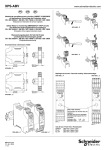
HR1S-AF
FR
GB
SAFETY RELAY MODULE OPERATING INSTRUCTIONS
DE
HR1S-AF....P
Module de surveillance pour circuits d'ARRET D'URGENCE
selon EN 418 / EN 60204-1
HR1S-AF....
Safety relay for monitoring EMERGENCY STOP circuits
according to EN 418 / EN 60204-1
Überwachungsbaustein für NOT AUS Kreise
gemäß EN 418 / EN 60204-1
Encombrements / Dimensions / Maße
24 33
13 23 3 S34 S39
A1 S3
id ec
H R 1S
24 33
13 233 S34 S39
A1 S3
id ec
K2
Fuse
33
13 23
99 mm
(3.89 in)
K1
K1
K2
34
14 24
E
K1
TY
UL E
SA FE Y M OD
RE LA
A1/A2
K2
-A F
Fuse
-A F
33
13 23
H R 1S
TY
UL
SA FE Y M OD
RE LA
A1/A2
K1
K2
34
14 24
1 S12
A2 S11 S22 34
14 S2
S1234
2 S11S22
A
4 S21
Repérage des bornes
Terminal marking
Klemmenanzeiger
22.5 mm
(0.89 in)
114 mm
(4.48 in)
HR1S-AF....
99 mm
(3.89 in)
13 23 24 33
A1 S33 S34 S39
A2 S11 S12
14 S21 S22 34
13 23 24 33
A1 S33 S34 S39
A2 S11 S12
14 S21 S22 34
HR1S-AF....P
114 mm
(4.48 in)
22.5 mm
(0.89 in)
HR1S-AF....
HR1S-AF....P
HR1S-AF....P
Application
Le module HR1S-AF sert à interrompre en toute sécurité un ou plusieurs
circuits. Il est conçu pour être intégré aux circuits d'arrêt d'urgence ou de
sécurité selon EN 60204-1. Il satisfait aux exigences des normes
européennes EN 418 pour les arrêts d'urgence et EN 60204-1 pour les
circuits de sécurité. Ces normes concernent en particulier les cas où
une seule commande doit couper plusieurs circuits (arrêt d'urgence à
action indirecte). Le module répond également aux exigences de
sécurité pour la surveillance électrique des interrupteurs de position
actionnés par des dispositifs de protection.
Le module est équipé de trois sorties de sécurité, libres de potentiel,de
catégorie d'arrêt 0 (EN 418, EN 60204-1).
Le module est conçu pour l'utilisation d'entrée à une ou deux voies. Nous
préconisons l'utilisation de deux voies d'entrée qui augmente ainsi le
niveau de sécurité. Ce mode opératoire permet d'intégrer toute la
connectique dans la surveillance. Tous les premiers défauts sont ainsi
détectés.
Fonction
La tension d'alimentation est appliquée aux bornes A1/A2 selon la valeur
sur la plaque signalétique. Les unités de commande sont raccordées de
la façon suivante:
L'utilisation d'une voie d'entrée :
Les unités de commande doivent être connectées à la borne A1.
Les bornes S11-S12 et S21-S22 doivent être shuntées.
L'utilisation de deux voies d'entrée :
Les unités de commande doivent être connectées aux bornes S11S12 et S21-S22.
Pour un raccordement à deux voies, les deux circuits d'entrée sont
alimentés des polarités différentes, ce qui permet la détection des
courts-circuits entre le + et le -.
5/10
Si le bouton de démarrage est connecté entre les bornes S33-S34
(utilisation recommandée), les sorties du module sont activées sur le
front descendant de l’impulsion du signal de sortie (lorsque le bouton de
démarrage est relâché).
La surveillance du bouton de démarrage correspond à la catégorie 4 de
la norme EN 954-1 à condition que:
- le bouton de démarrage soit raccordé entre les bornes S33-S34.
- les fils de connection du bouton soient protégés contre les courts
circuits.
- un bouton à reset automatique avec signalisation visuelle de la
position et approprié pour les conditios environnementales soit
utilisé.
Si le bouton de démarrage est connecté entre les bornes S33 et S39, les
sorties sont activées dès l’actionnement du bouton de démarrage, à
condition que les circuits d’entrée soient alors fermés.
Il est également possible de shunter les bornes S33-S39. Les sorties
sont ainsi activées dès que les deux signaux d’entrée entre les bornes
S11-S12 et S21-S22 sont fermés. Le temps de synchronisation entre les
deux circuits d’entrée est illimité.
Les contacts d’ouverture des relais ou contacteurs connectés en aval
des sorties de sécurité doivent être connectés en série avec le bouton
de démarrage, aux bornes S33-S34 ou S33-S39. La mise en marche de
l’appareil n’est ainsi possible que si les relais ou contacteurs connectés
en aval qui ont une fonction relative à la sécurité sont devenus inactifs
après avoir reçu l’ordre d’arrêt. La boucle de retour ainsi formée doit être
fermée pour chaque nouvelle mise en marche.
Un fusible électronique intégré protège le module contre la destruction
par courts-circuits externes (par exemple court-circuit entre le + et le des circuits d'entrée). Après élimination du défaut, le module est prêt à
être remis en service après quelques secondes.
HR1S-AF
!
SAFETY RELAY MODULE OPERATING INSTRUCTIONS
Indications supplémentaires
Le module ne contient pas de composants soumis à maintenance par
l'utilisateur. Pour l'autorisation d'un circuit de sécurité selon EN 60204-1:
1992 / EN 418 il est impératif d'utiliser seulement les circuits de sortie
libres de potentiel entre les bornes 13-14, 23-24 et 33-34.
!
Risques résiduels (EN 292-1, article 5)
An internal electronic fuse protects the module against destruction by
external short circuits (e. g., short circuits between the + and the - of the
input circuits). After elimination of the fault, the module is again operative
after a few seconds.
It is imperative that an external fuse be connected as shown on the
"WIRING DIAGRAM FOR MODULE HR1S-AF SAFETY RELAY". For
maximum protection of the outputs, please refer to "TECHNICAL
DATA".
Le schéma de raccordement proposé ci-dessous a été vérifié et testé
avec le plus grand soin dans des conditions de mise en service. Des
risques subsistent si :
a) le schéma de câblage ci-dessous est modifié par changement des
connexions ou l'adjonction de composants lorsque ceux-ci ne sont pas
ou insuffisamment intégrés dans le circuit de sécurité.
b) l'utilisateur ne respecte pas les exigences des normes de sécurité
pour le service, le réglage et la maintenance de la machine. Il est
important de respecter strictement les échéances de contrôle et de
maintenance.
Application
Safety systems are comprised of many components. No one safety
component will insure the safety of the system. The design of the
complete safety system should be considered before you begin. It is
very important to follow applicable safety standards when installing and
wiring these components.
The HR1S-AF module provides an interruption of one or several circuits
and is designed to be integrated in emergency stop or safety circuits
conforming to EN 60204-1. It meets the requirements of the European
standard EN 418 for emergency stop equipment and EN 60204-1 for
safety circuits in general. These standards concern applications where
several circuits are opened by one single command (emergency stop by
indirect action). The module also meets the safety requirements for
electrical monitoring of limit switches in lieu of emergency stop.
The module provides with three safety outputs of stop category 0
(EN 418, EN 60204-1).
The module is designed for use with one or two input channels. Due to
the extended possibilities of fault detection and resulting increased
safety level we recommend the use of two input channels. In this
operation mode the connection cables are included in the monitoring and
all initial faults will be detected.
!
Note
There are no user serviceable components in the module. For safety
circuits according to EN 60204-1:1992/EN418 safety devices must use
only the hard contacts outputs between terminals 13-14, 23-24 and 3334.
!
Residual Risk (EN 292-1, article 5)
The following wiring diagram has been tested and tried carefully under
actual service conditions. This module must be used for safety-related
functions in conjunction with the connected safety equipment and
devices that meet applicable standard requirements. A residual risk will
remain if:
a) it is necessary to modify this recommended circuit and if the added/
modified components are not properly integrated in the control circuit.
b) the user does not follow the required standards applicable to the
operation of the machine, or if the adjustments to and maintenance of
the machine are not properly made. It is strictly necessary to follow
the prescribed machine maintenance schedule.
c) the user does not select relays K3 and K4 with mechanically-linked
contacts.
! WARNING
IMPROPER CIRCUIT AND MAINTENANCE HAZARD
•
•
•
•
Wire safety relay using wiring diagram shown in following wiring diagram.
Wire to meet applicable standards requirements.
K3 and K4 must have mechanically-linked contacts.
Strictly follow prescribed maintenance schedule when making adjustments
to and maintenance of machine.
Failure to follow these instructions can result in death or serious injury.
Function
Anwendungsbereich
Use of one input channel:
Connect the control unit contacts to terminal A1. Terminals S11-S12
and S21-S22 must be shunted.
Das Gerät HR1S-AF dient dem sicherheitsgerichteten Unterbrechen
eines oder mehrerer Stromkreise(s) und ist zur Anwendung in Not-Ausund Sicherheitsstromkreisen gemäß EN 60204-1 bestimmt. Es erfüllt
die Europanormen EN 418 für Not-Aus Einrichtungen sowie EN 602041 für Sicherheitsstromkreise allgemein, zu denen im besonderen auch
die Fälle zählen, in denen mit einem Not-Aus Befehl mehrere
Stromkreise abgeschaltet werden sollen (indirekt wirkender Not-Aus).
Der Baustein erfüllt ebenfalls die sicherheitstechnischen Anforderungen
der elektrischen Überwachung von Positionsschaltern an trennenden
Schutzeinrichtungen.
Use of two input channels:
Connect the control unit contacts to terminals S11-S12 and S21-S22
If the start button is connected across terminals S33-S34
(recommended method), the module outputs are activated on the falling
front of the output signal pulse (when the start button is released).
Monitoring of the start button according to category 4 of EN 954-1 is
ensured when the following requirements are met:
- Connection of the start button to the terminals S33-S34.
- Placing of the connection wires in a way that they are protected from
short circuits.
- Use of a self-resetting button with visual position indication that is
suitable for the environmental conditions.
If the start button is connected across terminals S33 and S39, the
outputs are activated as soon as the start button is pressed, on condition
that the input circuits are then closed.
It is also possible to jumper terminals S33-S39. The outputs are thus
activated as soon as the two input signals across terminals S11-S12 and
S21-S22 area closed. The synchronization time between the two input
circuits is unlimited.
The relay or contactor opening contacts connected downstream of the
safety outputs must be connected in series with the start button, to
terminals S33-S34 or S33-S39. It is thus only possible to start the module
if the relays or contactors connected downstream which have a safetyrelated function have become inactive after receiving the stop command.
The return loop formed in this way must be closed for each new startup.
6/10
Der Baustein stellt drei potentialfreie Sicherheitsausgänge der StopKategorie 0 (EN 418, EN 60204-1) zur Verfügung.
Das Gerät ist für einkanalige und zweikanalige Eingangsbeschaltung
geeignet. Aufgrund der erweiterten Fehlerdetektionsmöglichkeiten und
des daraus resultierenden höheren Sicherheitsniveaus wird die
zweikanalige Eingangsbeschaltung empfohlen. In dieser Betriebsart
werden ebenfalls die Anschlußleitungen in die Überwachung
einbezogen und alle Erstfehler werden entdeckt.
Funktion
Die Versorgungsspannung wird gemäß angegebenem Wert auf dem
Typenschild an die Klemmen A1/A2 angeschlossen. Der Anschluß der
Befehlsgeräte ist wie folgt vorzunehmen:
Einkanalige Eingangsbeschaltung:
Die Befehlsgeräte sind an die Klemme A1 anzuschließen.
Die Klemmen S11-S12 sowie S21-S22 sind zu brücken.
Zweikanalige Eingangsbeschaltung:
Die Befehlsgeräte sind an die Klemmen S11-S12 und S21-S22
anzuschließen.
HR1S-AF
SAFETY RELAY MODULE OPERATING INSTRUCTIONS
Bei zweikanaligem Anschluß werden beide Eingangskreise mit unterschiedlicher Polarität versorgt, welches die Detektion von
Querschlüssen ermöglicht.
Wird die Starttaste zwischen den Klemmen S33-S34 angeschlossen
(empfohlene Verwendung), werden die Ausgänge des Bausteins mit
fallender Flanke des Startsignals (bei Loslassen des Starttasters)
durchgeschaltet.
Die Überwachung des Starttasters entspricht der Kategorie 4 gemäß
EN 954-1 im Falle der Erfüllung folgender Vorraussetzungen:
- Anschluß des Starttasters an die Klemmen S33-S34.
- Kurzschlußsichere Verlegung der Anschlußleitungen des
Starttasters.
- Verwendung eines für die Umgebungsbedingungen geeigneten,
selbst rückstellenden Tasters mit visueller Stellungserkennung.
vorausgangenen Abschaltbefehl abgefallen waren. Der so gebildete
Rückführkreis muß für jede neue Einschaltung geschlossen sein.
Eine eingebaute elektronische Sicherung schützt das Gerät HR1S-AF
vor Zerstörung durch äußere Kurzschlüsse (z.B. bei Querschlüssen in
der Eingangsbeschaltung). Nach Beseitigung der Fehlerursache ist der
Baustein nach einigen Sekunden wieder betriebsbereit.
!
Ergänzende Hinweise
Das Gerät enthält keine vom Anwender zu wartenden Bauteile. Zur
Freigabe eines Sicherheitsstromkreises gemäß EN 60204-1: 1992 / EN
418 sind ausschließlich die potentialfreien Ausgangskreise zwischen
den Klemmen 13-14, 23-24 und 33-34 zu verwenden.
!
Wird die Starttaste zwischen den Klemmen S33 und S39
angeschlossen, schalten die Ausgänge unmittelbar nach Betätigung des
Starttasters durch, sofern die Eingangskreise zu diesem Zeitpunkt
geschlossen sind.
Restrisiken (EN 292-1, Punkt 5)
Der nachstehende Schaltungsvorschlag wurde mit größter Sorgfalt
unter Betriebsbedingungen geprüft und getestet. Er erfüllt mit der
angeschlossenen Peripherie sicherheitsgerichteter Einrichtungen und
Schaltgeräte insgesamt die einschlägigen Normen. Restrisiken
verbleiben wenn:
Es ist ebenfalls möglich, die Klemmen S33-S39 zu brücken. Die
Ausgänge schalten in diesem Fall durch, sobald beide Eingangssignale
zwischen den Klemmen S11-S12 sowie S21-S22 geschlossen werden.
Die Synchronisationszeit zwischen den beiden Eingangskreisen ist
unendlich.
Die Öffnerkontakte der den Sicherheitsausgängen nachgeschalteten
Relais oder Schütze sind in Reihe mit der Starttaste an die Klemmen
S33-S34 oder S33-S39 anzuschließen. Dadurch gelingt eine
Einschaltung des Gerätes nur dann, wenn die nachgeschalteten Relais
oder Schütze, welche sicherheitsrelevante Funktion haben, nach einem
a) vom vorgeschlagenen Schaltungskonzept abgewichen wird und
dadurch die angeschlossenen sicherheitsrelevanten Geräte oder
Schutzeinrichtungen möglicherweise nicht oder nur unzureichend in die
Sicherheitsschaltung einbezogen werden.
b) vom Betreiber die einschlägigen Sicherheitsvorschriften für Betrieb,
Einstellung und Wartung der Maschine nicht eingehalten werden. Hier
sollte auf strenge Einhaltung der Intervalle zur Prüfung und Wartung der
Maschine geachtet werden.
Schéma de raccordement pour HR1S-AF
Wiring diagram for HR1S-AF
Anschlußschema für HR1S-AF
! DANGER
HAZARDOUSVOLTAGE
• Disconnect all power before working on equipment.
Raccordement du bouton à une voie
One channel connection of the button
Tasteranschluß einkanalig
S1 11
Arrêt d'urgence
Emergency stop
12 NOT-AUS
Electric shock will result in death or serious injury.
Raccordement du bouton à deux voies, avec détection des courts-circuits
Two channel connection of the button, with short circuit detection (recommended application)
Tasteranschluß zweikanalig, mit Querschlußerkennung
S1 11
21
12
22
Arrêt d'urgence
Emergency stop
NOT-AUS
Protecteur (fermé)
Protective guard (closed)
Schutzgitter (geschlossen)
Input A
Raccordement de plusieurs boutons arrêt d'urgence
Connection of several emergency stop buttons
Anschluß mehrerer NOT-AUS Taster
Sans surveillance du bouton de démarrage
Without monitoring of the start button
Ohne Start-Taster Überwachung
S1
Input B
S2
S2 13 Marche
Start
14 Start
7/10
S1 11
21
12
22
S2 11
21
12
22
S3 11
21
12
22
Ouvrir le protecteur
Open the protective guard
Schutzgitter öffnen
Arrêt d'urgence 1
Emergency stop 1
NOT-AUS 1
Arrêt d'urgence 2
Emergency stop 2
NOT-AUS 2
Arrêt d'urgence 3
Emergency stop 3
NOT-AUS 3
Avec surveillance du bouton de démarrage
With monitoring of the start button
Mit Start-Taster Überwachung
S2 13 Marche
Start
14 Start
Sans bouton de démarrage (démarrage automatique)
Without start button (automatic start)
Ohne Start-Taster (automatischer Start)
HR1S-AF
SAFETY RELAY MODULE OPERATING INSTRUCTIONS
Schéma de raccordement pour HR1S-AF
Wiring diagram for HR1S-AF
Anschlußschema für HR1S-AF
F1
L(+)
24V AC/DC
K3
S2 13
K4
START 14
(1)
ESB
avec sans
with without
mit
ohne
Diagnostic du système à l'aide des
DEL dans le couvercle du boîtier:
System diagnostics LEDs on the front
cover:
Systemdiagnose mittels LED-Anzeige
im Gehäusedeckel:
T
K1
HR1S-AF
LOGIC
K2
Disposition des DEL dans le
couvercle du boîtier
Arrangement of LEDs in the
cover
Anordnung der Leuchtdioden
im Gehäusedeckel
1
A1/A2 - Fuse
2
K1
3
K2
S1 11
21
NOT-AUS 12
22
K3
K4
N(–)
(1) =
ESC =
Conditions externes de démarrage
External start conditions
Externe Start Bedingungen
Starttasterüberwachung
DEL 1: (A1/A2 - Fuse)
LED 1: (A1/A2 - Fuse)
LED 1: (A1/A2 - Fuse)
Présence de tension d'alimentation aux bornes
A1/A2. La DEL s'éteint, lorsqu'il n'y a plus de
tension ou lorsque le fusible électronique est
activé.
Supply voltage is applied to terminals A1/A2.
The LED extinguishes if there is no supply
voltage or the electronic fuse is activated.
Versorgungsspannung an den Klemmen A1/A2
ist vorhanden. Die LED verlischt bei fehlender
Versorgungsspannung oder Ansprechen der
elektronischen Sicherung.
DEL 2: (K1)
LED 2: (K1)
LED 2: (K1)
Relais K1 excité.
Relay K1 energised.
Relais K1 angezogen.
DEL 3: (K2)
LED 3: (K2)
LED 3: (K2)
Relais K2 excité.
Relay K2 energised.
Relais K2 angezogen.
Durée de vie des contacts de sortie selon EN 60947-5-1 / tableau C2
Electrical life of the output contacts determined by EN 60947-5-1 / table C2
Lebensdauer der Ausgangskontakte gemäß EN 60947-5-1 / Tabelle C2
100
AC1: 230V
Courant de commutation x 0,1 A
Nominal Operating Current x 0.1 A
Schaltstrom x 0,1 A
AC15: 230V
DC1: 24V
DC13: 24V
10
1
104
105
106
Cycles de manoeuvre
Operation Cycles
Schaltspiele
8/10
107
HR1S-AF
SAFETY RELAY MODULE OPERATING INSTRUCTIONS
Diagramme fonctionnel du HR1S-AF
Functional Diagram HR1S-AF
Funktionsdiagramm HR1S-AF
Fonction arrêt d'urgence
Emergency stop function
Not-Aus Funktion
Entrée A (S11-S12)
Input A (S11-S12)
Eingang A (S11-S12)
Entrée B (S21-S22)
Input B (S21-S22)
Eingang B (S21-S22)
Bouton de démarrage S33-S34 (F)
Start button S33-S34 (NO)
Start-Taster S33-S34 (S)
Bouton de démarrage S33-S39 (F)
Start button S33-S39 (NO)
Start-Taster S33-S39 (S)
Sortie 13-14 (F)
Output 13-14 (NO)
Ausgang 13-14 (S)
Sortie 23-24 (F)
Output 23-24 (NO)
Ausgang 23-24 (S)
Sortie 33-34 (F)
Output 33-34 (NO)
Ausgang 33-34 (S)
➀
➁
surveillance du bouton
➀ Avec
de démarrage
With start button monitoring
Mit Start-Tasterüberwachung
surveillance du bouton
➁ Sans
de démarrage
Without start button monitoring
Ohne Start-Tasterüberwachung
Fonction protecteur avec démarrage automatique
Protective guard function with automatic start
Schutztür Funktion mit automatischem Start
Entrée A (S11-S12)
Input A (S11-S12)
Eingang A (S11-S12)
Entrée B (S21-S22)
Input B (S21-S22)
Eingang B (S21-S22)
Shunt à S33-S39
Jumper at S33-39
Brücke an S33-S39
Sortie 13-14 (F)
Output 13-14 (NO)
Ausgang 13-14 (S)
Sortie 23-24 (F)
Output 23-24 (NO)
Ausgang 23-24 (S)
Sortie 33-34 (F)
Output 33-34 (NO)
Ausgang 33-34 (S)
Légende:
Legend:
Legende:
Activé
ON
Ein
Désactivé
OFF
Aus
CARACTERISTIQUES TECHNIQUES
TECHNICAL DATA
TECHNISCHE DATEN
- Raccordement
HR1S-AF...
Connection un fil
Sans embout:
rigide 0,14-2,5 mm2 / flexible 0,14-2,5 mm2
Flexible avec embout
(sans colleret plastique): 0,25-2,5 mm2
(avec colleret plastique): 0,25-1,5 mm2
Connection deux fils
Sans embout:
rigide 0,14-0,75 mm2 / flexible 0,14-0,75 mm2
Flexible avec embout
(sans colleret plastique): 0,25-0,5 mm2
Flexible avec embout TWIN
(avec colleret plastique): 0,5-1,5 mm2
- Connection wires
HR1S-AF...
Single wire connection
Without end sleeve for strands:
rigid 0.14-2.5 mm2 / flexible 0.14-2.5 mm2
Flexible with end sleeve for strands
(without plastic sleeve): 0.25-2.5 mm2
(with plastic sleeve):
0.25-1.5 mm2
Multiple-wire connection (2 wires max.)
Without end sleeve for strands:
rigid 0.14-0.75 mm2 / flexible 0.14-0.75 mm2
Flexible with end sleeve for strands
(without plastic sleeve): 0.25-0.5 mm2
Flexible with TWIN-end sleeve for strands
(with plastic sleeve):
0.5-1.5 mm2
- Anschlußquerschnitte
HR1S-AF...
Einzelleiteranschluß
Ohne Aderendhülse:
starr 0,14-2,5 mm2 / flexibel 0,14-2,5 mm2
Flexibel mit Aderendhülse
(ohne Kunststoffhülse): 0,25-2,5 mm2
(mit Kunststoffhülse):
0,25-1,5 mm2
Mehrleiteranschluß (2 Leiter max.)
Ohne Aderendhülse:
starr 0,14-0,75 mm2 / flexibel 0,14-0,75 mm2
Flexibel mit Aderendhülse
(ohne Kunststoffhülse): 0,25-0,5 mm2
Flexibel mit TWIN-Aderendhülse
(mit Kunststoffhülse):
0,5-1,5 mm2
9/10
HR1S-AF
SAFETY RELAY MODULE OPERATING INSTRUCTIONS
HR1S-AF...P
Connection un fil
Sans embout:
rigide 0,2-2,5 mm2 / flexible 0,2-2,5 mm2
Flexible avec embout
(sans colleret plastique): 0,25-2,5 mm2
(avec colleret plastique): 0,25-2,5 mm2
Connection deux fils
Sans embout:
rigide 0,2-1 mm2 / flexible 0,2-1,5 mm2
Flexible avec embout
(sans colleret plastique): 0,25-1 mm2
Flexible avec embout TWIN
(avec colleret plastique): 0,5-1,5 mm2
- Fixation du boîtier:
Encliquetage sur profile chapeau 35 mm
selon DIN EN 50022
- Degré de protection selon IEC 529:
Bornes
: IP20
Boîtier
: IP40
- Poids:
0,25 kg
- Position de montage:
indifférente
- Température de fonctionnement:
- 100 C / + 550 C
- Catégorie de surtension III (4kV)
Degré de pollution 2
Tension assignée d’isolement 300V
selon DIN VDE 0110 / partie 1+2
- Tension d’alimentation U E selon IEC 38:
24V AC/DC
(+10% / -15%)
(voir plaque signalétique)
Protection max.: 4 A gL
- Puissance consommée:
Version 24V AC/DC
≤ 5 VA
- Sorties de sécurité (libres de potentiel):
13-14, 23-24, 33-34
- Capacité de coupure maxi des sorties:
AC 15 - C300
(1800VA/180VA)
DC 13
24V/1,5A - L/R=50ms
- Limite de courants cumulés (charge
simultanée de plusieurs circuits de sortie):
Σ Ith ≤ 18 A
6A
6A
- Mounting:
Mounting on 35 mm DIN rail
according to DIN EN 50022
- Degree of protection according to IEC 529:
Terminals : IP20
Enclosure : IP40
- Weight:
0.25 kg (8.8 oz)
- Mounting position:
any plane
- Ambient operating temperature:
-100 C to +550 C (+ 140 F to +1300 F)
- Overvoltage category III (4 kV)
Pollution degree 2
Rated insulation voltage 300V
according to DIN VDE 0110 / part 1+2
- Supply voltage U E according to IEC 38:
24V AC/DC
(+10% / -15%)
(refer to device nameplate for supply
voltage)
Max. protection: 4 A fuse (gL)
- Power consumption:
Version 24V AC/DC
≤ 5 VA
- Safety outputs:
13-14, 23-24, 33-34
- Maximum switching capacity of outputs:
AC 15 - C300
(1800VA/180VA)
DC 13
24V/1.5A - L/R=50ms
- The sum of simultaneous currents on all of
the outputs is limited to:
Σ Ith ≤ 18 A
6A
- Protection des sorties:
max.: 4 A gL ou 6A rapide
- Temps de réponse:
≤ 40 ms
- Temps de synchronisation entre entrée A et
entrée B à l'utilisation sans bouton de
démarrage:
t=∞
L'appareil est aussi capable de commuter des
charges faibles (17V / 10mA minimum) à
condition que le contact n'ait jamais commuté
de forte charge auparavant, car la couche d'or
revêtant le contact pourrait être altérée.
Calcul de la resistance du câblage R L entre les
bornes S11/S12 et S21/S22 en fonction de la
tension d'alimentation interne U S11/S21 (Bornes
S11/S21).
U S11/S21 – U min
RL ≤
I min
- Tension minimale U min (20° C)
Version
U S11/S21
U min
I min
24V AC/DC
UE –2 V
18 V
90mA
- Resistance du câblage maximal R L:
max. 28 Ohms
10/10
HR1S-AF...P
Single wire connection
Without end sleeve for strands:
rigid 0.2-2.5 mm2 / flexible 0.2-2.5 mm2
Flexible with end sleeve for strands
(without plastic sleeve): 0.25-2.5 mm2
(with plastic sleeve):
0.25-2.5 mm2
Multiple-wire connection (2 wires max.)
Without end sleeve for strands:
rigid 0.2-1 mm2 / flexible 0.2-1.5 mm2
Flexible with end sleeve for strands
(without plastic sleeve): 0.25-1 mm2
Flexible with TWIN-end sleeve for strands
(with plastic sleeve):
0.5-1.5 mm2
HR1S-AF...P
Einzelleiteranschluß
Ohne Aderendhülse:
starr 0,2-2,5 mm2 / flexibel 0,2-2,5 mm2
Flexibel mit Aderendhülse
(ohne Kunststoffhülse): 0,25-2,5 mm2
(mit Kunststoffhülse):
0,25-2,5 mm2
Mehrleiteranschluß (2 Leiter max.)
Ohne Aderendhülse:
starr 0,2-1 mm2 / flexibel 0,2-1,5 mm2
Flexibel mit Aderendhülse
(ohne Kunststoffhülse): 0,25-1 mm2
Flexibel mit TWIN-Aderendhülse
(mit Kunststoffhülse):
0,5-1,5 mm2
- Gehäusebefestigung:
Schnappbefestigung auf 35 mm
Normschiene nach DIN EN 50022
- Schutzart gemäß IEC 529:
Klemmen : IP20
Gehäuse : IP40
- Gewicht:
0,25 kg
- Einbaulage:
beliebig
- Umgebungstemperatur im Betrieb:
- 100 C / + 550 C
- Überspannungskategorie III (4 kV)
Verschmutzungsgrad 2
Bemessungsisolationsspannung 300V
gemäß DIN VDE 0110 / Teil 1+2
- Anschlußspannung U E gemäß IEC 38:
24V AC/DC
(+10% / -15%)
(Siehe Typenschild)
Absicherung max.: 4 A gL
- Eigenverbrauch:
Version 24V AC/DC
≤ 5 VA
- Sicherheitsausgänge (potentialfrei):
13-14, 23-24, 33-34
- Max. Schaltleistung der Ausgangskanäle:
AC 15 - C300
(1800VA/180VA)
DC 13
24V/1,5A - L/R=50ms
- Summenstrombegrenzung bei gleichzeitiger Belastung mehrerer Ausgangskreise:
Σ Ith ≤ 18 A
6A
6A
6A
6A
- Protection of outputs:
max.: 4 A fuse (gL) Or 6A fastblow
- Response time:
≤ 40 ms
- Synchronisation time between Input A and
Input B without use of start button
(automatic start):
t=∞
Minimum switching ratings of outputs:
The device is capable to switch low voltage
loads (min. 17 V/10 mA) provided that the
contact has never been used with higher
loads.
Calculation of wiring resistance R L between
terminals S11/S12 and S21/S22 depending on
the internal supply voltage U S11/S21 (Terminals
S11/S21).
U S11/S21 – U min
RL ≤
I min
- Minimal voltage U min (20° C)
Version
U S11/S21
U min
I min
24V AC/DC
U E –2 V
18 V
90mA
- Maximum wiring resistance R L:
max. 28 Ohm
6A
6A
- Absicherung der Ausgangskreise:
max.: 4 A gL oder 6A Flink
- Ansprechzeit:
≤ 40 ms
- Synchronisationszeit zwischen Input A und
Input B bei Verwendung ohne Starttaster:
t=∞
Das Gerät ist ebenfalls zum Schalten von
Kleinstlasten (min. 17V / 10mA) geeignet. Dies
ist jedoch nur dann möglich, wenn bisher über
diesen Kontakt keine höheren Lasten
geschaltet wurden, da hierdurch die
Kontaktvergoldung abgebrannt sein könnte.
Berechnung des Leitungswiderstandes R L
zwischen den Klemmen S11/S12 und S21/S22
in Abhängigkeit von der internen
Versorgungsspannung U S11/S21 (Klemmen
S11/S21).
U S11/S21 – U min
RL ≤
I min
- Minimalspannung U min (20° C)
Version
U S11/S21
U min
I min
24V AC/DC
UE –2 V
18 V
90mA
- Maximaler Leitungswiderstand R L:
max. 28 Ohm