1
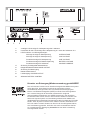
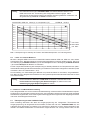
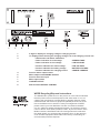
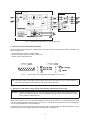
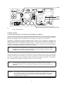
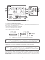
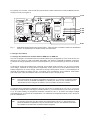
BEDIENUNGSANLEITUNG
OWNER’S MANUAL
MODE D’EMPLOI
LADEGERÄT DEM 313
3
Merkmale
— vollautomatisches Ladegerät 24V/4A für konstante I/U Batterieladung im Bereitschafts-ParallelBetrieb
— Regelung der Ladespannung mit primär getaktetem Schaltregler mit hohem Wirkungsgrad
— Ladeausgang mit Kurzschluß- und Verpolungsschutz
— integriertes Batterie-Überwachungs-Modul mit Überspannungsschutz, Tiefentladeschutz,
Netzspannungs-Überwachung, Batteriespannungs-Überwachung ,Verbesserte Ladekreis-Überwachung, LED-Störungs-Anzeige, Sammelstörmeldung mit potentialfreiem Kontakt
— eingebaute 3-stellige LCD-Anzeige für Ladespannung und Ladestrom
— Temperaturnachführung der Ladespannung im Standby-Betrieb
— Anschluß BATTERY CONTROL mit allen Steuerfunktionen und Störmeldeausgang
— 19"- Gehäuse mit 2HE
WICHTIGE SICHERHEITSHINWEISE
Das Blitzsymbol innerhalb eines gleichseitigen Dreiecks soll den Anwender auf nicht isolierte Leitungen
und Kontakte im Geräteinneren hinweisen, an denen
hohe Spannungen anliegen, die im Fall einer
Berührung zu lebensgefährlichen Stromschlägen
führen können.
1.
2.
3.
4.
5.
6.
7.
8.
9.
10.
11.
12.
13.
14.
15.
16.
Das Ausrufezeichen innerhalb eines gleichseitigen
Dreiecks soll den Anwender auf wichtige Bedienungssowie Servicehinweise in der zum Gerät gehörenden Literatur aufmerksam machen.
Lesen Sie diese Hinweise.
Heben Sie diese Hinweise auf.
Beachten Sie alle Warnungen.
Richten Sie sich nach den Anweisungen.
Betreiben Sie das Gerät nicht in unmittelbarer Nähe von Wasser.
Verwenden Sie zum Reinigen des Gerätes ausschließlich ein trockenes Tuch.
Verdecken Sie keine Lüftungsschlitze. Beachten Sie bei der Installation des Gerätes stets die entsprechenden
Hinweise des Herstellers.
Vermeiden Sie die Installation des Gerätes in der Nähe von Heizkörpern, Wärmespeichern, Öfen oder anderer
Wärmequellen.
Achtung: Gerät nur an Netzsteckdose mit Schutzleiteranschluss betreiben. Setzen Sie die Funktion des
Schutzleiteranschlusses des mitgelieferten Netzanschlusskabels nicht außer Kraft. Sollte der Stecker des
mitgelieferten Kabels nicht in Ihre Netzsteckdose passen, setzen Sie sich mit Ihrem Elektriker in Verbindung.
Sorgen Sie dafür, dass das Netzkabel nicht betreten wird. Schützen Sie das Netzkabel vor Quetschungen
insbesondere am Gerätestecker und am Netzstecker.
Verwenden Sie mit dem Gerät ausschließlich Zubehör/Erweiterungen, die vom Hersteller hierzu vorgesehen sind.
Ziehen Sie bei Blitzschlaggefahr oder bei längerem Nichtgebrauch den Netzstecker.
Überlassen Sie sämtliche Servicearbeiten und Reparaturen einem ausgebildeten Kundendiensttechniker.
Servicearbeiten sind notwendig, sobald das Gerät auf irgendeine Weise beschädigt wurde, wie z.B. eine
Beschädigung des Netzkabels oder des Netzsteckers, wenn eine Flüssigkeit in das Gerät geschüttet wurde oder ein
Gegenstand in das Gerät gefallen ist, wenn das Gerät Regen oder Feuchtigkeit ausgesetzt wurde, oder wenn es nicht
normal arbeitet oder fallengelassen wurde.
Stellen Sie bitte sicher, dass kein Tropf- oder Spritzwasser ins Geräteinnere eindringen kann. Stellen Sie keine mit
Flüssigkeiten gefüllten Objekte, wie Vasen oder Trinkgefässe, auf das Gerät.
Um das Gerät komplett spannungsfrei zu schalten, muss der Netzstecker gezogen werden.
Beim Einbau des Gerätes ist zu beachten, dass der Netzstecker leicht zugänglich bleibt.
WICHTIGE SERVICEHINWEISE
ACHTUNG:
Diese Servicehinweise sind ausschliesslich für qualifiziertes Servicepersonal vorgesehen.
Um die Gefahr eines elektrischen Schlages zu vermeiden, führen Sie keine Wartungsarbeiten durch,
die nicht in der Bedienungsanleitung beschrieben sind, ausser Sie sind hierfür qualifiziert. Überlassen
Sie sämtliche Servicearbeiten und Reparaturen einem ausgebildeten Kundendiensttechniker.
1. Bei Reparaturarbeiten im Gerät sind die Sicherheitsbestimmungen nach EN 60065 (VDE 0860) einzuhalten.
2. Bei allen Arbeiten, bei denen das geöffnete Gerät mit Netzspannung verbunden ist und betrieben wird, ist ein Netz trenntransformator zu verwenden.
3. Vor einem Umbau mit Nachrüstsätzen, Umschaltung der Netzspannung oder sonstigen Modifikationen ist das Gerät
stromlos zu schalten.
4. Die Mindestabstände zwischen netzspannungsführenden Teilen und berührbaren Metallteilen
(Metallgehäuse) bzw. zwischen den Netzpolen betragen 3 mm und sind unbedingt einzuhalten.
Die Mindestabstände zwischen netzspannungsführenden Teilen und Schaltungsteilen, die nicht mit dem Netz
verbunden sind (sekundär), betragen 6 mm und sind unbedingt einzuhalten.
5. Spezielle Bauteile, die im Stromlaufplan mit dem Sicherheitssymbol gekennzeichnet sind (Note), dürfen nur durch
Originalteile ersetzt werden.
6. Eigenmächtige Schaltungsänderungen dürfen nicht vorgenommen werden.
7. Die am Reparaturort gültigen Schutzbestimmungen der Berufsgenossenschaften sind einzuhalten. Hierzu gehört
auch die Beschaffenheit des Arbeitsplatzes.
8. Die Vorschriften im Umgang mit MOS - Bauteilen sind zu beachten.
NOTE:
SAFETY COMPONENT ( MUST BE REPLACED BY ORIGINAL PART )
2
1
2
3
4
5
6
7
8
9
3-stellige LCD-Anzeige für Ladespannung oder Ladestrom
Umschalter für die LCD-Anzeige der Ladespannung in V oder den Ladestrom in A
LED-Funktions- und Störungsanzeigen:
Störungs-Anzeige für Überspannung
OVERVOLTAGE
Störungs-Anzeige für Unterspannung
LOW VOLTAGE
Funktions-Anzeige für Netzspannung
LINE VOLTAGE
Funktions-Anzeige für Batterie-Spannung
BATTERY VOLTAGE
Funktions-Anzeige für Ladestrom
CHARGE CURRENT
Sicherung für Kaltgeräte-Netzsteckdose
Kaltgeräte-Netzsteckdose MAINS OUTPUT
Sicherung für Netzeingang
Netzanschluß-Stecker
Ladeausgang CHARGE OUTPUT
Stiftleiste BATTERY CONTROL
Hinweise zur Entsorgung/Wiederverwendung gemäß WEEE
Das auf unserem Produkt und im Handbuch abgedruckte Mülltonnensymbol
weist darauf hin, dass dieses Produkt nicht gemeinsam mit dem
Haushaltsmüll entsorgt werden darf. Für die korrekte Entsorgung der
Elektro- und Elektronik-Altgeräte (WEEE) am Ende ihrer Nutzungsdauer
ist in unserer Kategorie der Hersteller verantwortlich. Aufgrund
unterschiedlicher Regelungen zur WEEE-Umsetzung in den einzelnen
EU-Staaten bitten wir Sie, sich an Ihren örtlichen Händler zu wenden. Wir
haben ein eigenes System zur Verarbeitung elektronischer Abfälle und
gewährleisten die kostenfreie Entgegennahme aller Produkte der EVI Audio
GmbH: Telex, Dynacord, Electro-Voice, Midas Consoles, KlarkTeknik und
RTS. Wir haben mit dem Händler, bei dem Sie Ihr Produkt gekauft haben,
eine Vereinbarung getroffen, dass alle nicht mehr verwendbaren Geräte
zur umweltgerechten Entsorgung kostenfrei an das Werk in Straubing
zurückgeschickt werden.
3
Inhaltsverzeichnis
SICHERHEITSHINWEISE / SERVICEHINWEISE . . . . . . . . . . . . . . . . . . . . . 2
1.
Verwendung . . . . . . . . . . . . . . . . . . . . . . . . . . . . . . . . . . . . . . . . . . . . . . . 5
2.
Installationshinweise . . . . . . . . . . . . . . . . . . . . . . . . . . . . . . . . . . . . . . . . 5
3.
Vor der Inbetriebnahme . . . . . . . . . . . . . . . . . . . . . . . . . . . . . . . . . . . . . . 5
3.1 Steueranschluß BATTERY CONTROL . . . . . . . . . . . . . . . . . . . . . . . . . . 6
4.
Umschaltung der Netzspannung . . . . . . . . . . . . . . . . . . . . . . . . . . . . . . . 6
5.
Batterie-Ladung . . . . . . . . . . . . . . . . . . . . . . . . . . . . . . . . . . . . . . . . . . . . 7
5.1 Laden der Batterien in den Batterie-Modulen DEM 316 oder DEM 317 . 7
5.2 Laden von anderen Batterien . . . . . . . . . . . . . . . . . . . . . . . . . . . . . . . . . . 8
6.
Funktions- und Betriebsbeschreibung . . . . . . . . . . . . . . . . . . . . . . . . . . . 8
6.1 Überspannungsschutz OVERVOLTAGE . . . . . . . . . . . . . . . . . . . . . . . . . 8
6.2 Unterspannungs-Überwachung LOW VOLTAGE . . . . . . . . . . . . . . . . . . 9
6.3 Netzspannungs-Überwachung LINE VOLTAGE . . . . . . . . . . . . . . . . . . . 9
6.4 Batteriespannungs-Überwachung BATTERY VOLTAGE . . . . . . . . . . . . 9
6.5 Ladekreis-Überwachung CHARGE CURRENT . . . . . . . . . . . . . . . . . . . . 9
6.6 Verpolungsschutz und Kurzschlußschutz . . . . . . . . . . . . . . . . . . . . . . . . 9
6.7 Sammelstörmeldung . . . . . . . . . . . . . . . . . . . . . . . . . . . . . . . . . . . . . . . . 9
6.8 Volt-/Amperemeter . . . . . . . . . . . . . . . . . . . . . . . . . . . . . . . . . . . . . . . . . . 9
6.9 Temperaturnachführung. . . . . . . . . . . . . . . . . . . . . . . . . . . . . . . . . . . . . . 10
7
Sicherungen . . . . . . . . . . . . . . . . . . . . . . . . . . . . . . . . . . . . . . . . . . . . . . . 10
8
Begriffserklärungen . . . . . . . . . . . . . . . . . . . . . . . . . . . . . . . . . . . . . . . . . 10
9.
Zulassungen und Normen . . . . . . . . . . . . . . . . . . . . . . . . . . . . . . . . . . . . 11
10. Technische Daten Ladegerät DEM 313 . . . . . . . . . . . . . . . . . . . . . . . . . . 11
4
1. Verwendung
Das Ladegerät DEM 313 ist speziell für die vollautomatische Ladung und Überwachung von Batterien in
Notstrom-Versorgungen von Alarmierungs-Anlagen entwickelt worden. Zusammen mit den Batterie-Modulen DEM 316 mit 38 Ah oder DEM 317 mit 65 Ah Nennkapazität ergibt diese Kombination eine
zuverlässige und problemlose Notstromversorgung im Bereitschafts-Parallelbetrieb. Mit dem integrierten
Überwachungsmodul ist eine ständige Kontrolle der Batterie sichergestellt.
2. Installationshinweise
Die Belüftung des Gerätes darf nicht blockiert werden. Das Gerät ist zu schützen vor:
- Tropf- oder Spritzwasser
- direkter Sonnenbestrahlung
- hoher Umgebungstemperatur oder unmittelbarer Einwirkung von Wärmequellen
- hoher Luftfeuchtigkeit
- starken Staubablagerungen
- starken Vibrationen
Wenn das Gerät direkt von einem kalten an einen warmen Ort gebracht wird, kann sich Feuchtigkeit auf
Innenteilen niederschlagen. Das Gerät darf erst in Betrieb genommen werden, wenn es sich auf die
geänderte Temperatur erwärmt hat (nach etwa einer Stunde).
Sollte ein fester Gegenstand oder Flüssigkeit in das Gehäuse gelangen, trennen Sie sofort die Stromquellen vom Gerät ab und lassen das Gerät von einer DYNACORD Servicestelle überprüfen, bevor Sie
es weiterverwenden.
Zur Reinigung des Gerätes dürfen keine Sprühmittel verwendet werden, da diese dem Gerät schaden
und sich plötzlich entzünden können.
3. Vor der Inbetriebnahme
Vor dem Anschluß des Gerätes an das Netz sind die folgenden Anschlüsse herzustellen:
•
Die Stiftleiste BATTERY CONTROL (9) des Ladegerätes ist mit der Stiftleiste BATTERY CONTROL
des Batterie-Moduls zu verbinden (siehe auch Bild 1 und Abschnitt 3.1).
•
Der Ladeausgang CHARGE OUTPUT (8) des Ladegerätes ist mit dem Ladeeingang CHARGE
CURRENT des Batterie-Moduls zu verbinden, wobei auf richtige Polung zu achten ist (siehe Bild 1).
Der Querschnitt der Leitung zwischen dem Ladegerät und dem Batterie-Modul soll mindestens 2.5
mm² betragen. Für die Anschlüsse sind isolierte AMP-Flachsteckhülsen 6.3x0.8 mm zu verwenden.
Die Leitungslänge darf 2m nicht überschreiten.
•
An der Kaltgeräte-Netzsteckdose MAINS OUTPUT (5) kann ein weiteres Gerät angeschlossen
werden, wenn seine Stromaufnahme 4 A nicht überschreitet. Die Kaltgeräte-Netzsteckdose MAINS
OUTPUT (5) ist mit einer Sicherung (4) mit dem Wert T4A vor Überlastung geschützt. Ein größerer
Sicherungswert als T4A ist nicht zulässig.
•
Wenn alle Verbindungen richtig hergestellt wurden, ist das Gerät über das mitgelieferte Netzkabel an
das Netz anzuschließen. Geräteseitig ist das Netzanschlußkabel an den 3-poligen NetzanschlußStecker (7) anzustecken.
Achtung
Das Gerät ist ab Werk auf 230V~ AC eingestellt. Eine Umschaltung auf 115V~ AC kann
durch ändern von Drahtbrücken im Geräteinnern vorgenommen werden
(siehe Abschnitt 4).
5
Bild 1 Anschluß der Batterie an das Ladegerät
3.1
Steueranschluß BATTERY CONTROL
An der 15-poligen D-Sub-Stiftleiste BATTERY CONTROL ( 9) stehen verschiedene Steuer-Ein-/
Ausgänge (siehe auch Bild 2) zur Verfügung:
- Eingang Temperatursensor +TEMP / -TEMP
- Ausgang Tiefentlade-Relais +LVR / -LVR
- Störmelde-Ausgang FAILURE
Bild 2 Anschlüsse der BATTERY CONTROL Stiftleiste
Hinweis Die Schaltleistung des Störmelde-Ausgangs beträgt max. 30V DC / 0.1A. Die Kontakte 2, 3
und 13 sind ausschließlich für Testzwecke vorgesehen und dürfen nicht beschaltet werden.
4. Umschaltung der Netzspannung (nur vom Fachmann auszuführen)
Achtung
Vor dem Entfernen der oberen Geräteabdeckung muß das Gerät für mindestens 2
Minuten vom Netz getrennt sein, da die Kondensatoren im Gerät gefährliche Spannung
führen und sich erst entladen müssen.
Für 115V~ AC Betrieb ist die Netzsicherung (6) durch eine träge 2A Sicherung mit dem Aufdruck T2A zu
ersetzen. Die Beschriftung T1A oberhalb der Netzsicherung (6) ist mit einem Aufkleber T2A zu
überkleben. Die Beschriftung 230V~ oberhalb des Netzanschluß-Steckers (7) ist mit dem Aufkleber
115V~ zu überkleben. Die erforderlichen Aufkleber befinden sich im Gerät auf der rechten Seite neben
der Printplatte 85254 .
6
Für die Umschaltung auf 115V~ AC Betrieb sind auf der Printplatte 85254 die Drahtbrücken S501, S502
und S504 einzulöten und die Drahtbrücke S 503 zu entfernen (siehe Bild 3).
F 503
S 504
S 503
S 502
S 501
Bild 3
Printplatte 85254 Lage der Drahtbrücken S501 - S504 für die Netzspannungs-Umschaltung
und Lage der Ausgangs-Sicherung F503
5. Batterie-Ladung
5.1
Laden der Batterien in den Batterie-Modulen DEM 316 oder DEM 317
Wenn das Ladegerät richtig mit dem Batterie-Modul verbunden wurde (siehe Abschnitt 3) und die
Netzspannung vorhanden ist, leuchten die grünen LED (3) LINE VOLTAGE, BATTERY VOLTAGE und
CHARGE CURRENT. Der Ladestrom wird von der LCD-Anzeige (1) angezeigt, wenn Schalter (2) auf
Position A geschaltet ist.
Die Ladung der Batterie erfolgt mit konstantem Ladestrom von ca. 4 A. Zum Ladeschluß wird der
Ladestrom mit steigender Gegenspannung der Batterie schnell keiner und fällt zum Ladeschluß hin auf
einen kleinen Erhaltungsstrom von ca. 0.2 mA / Ah zu ladende Batteriekapazität ab, der für die Batterie
dauernd verträglich ist. Dieser Wert kann, besonders bei älteren Batterien streuen und zwischen 0.2 mA
bis 10 mA pro Ah liegen.
Hinweis
Bei fehlerhaftem Anschluß fließt kein Ladestrom und die grüne LED (3) CHARGE
CURRENT leuchtet nicht. Bitte prüfen Sie alle Verbindungen zwischen Batterie und
Ladegerät, alle Sicherungen und die Netzspannung.
Die Ladungserhaltung der Batterie erfolgt mit einer konstanten Spannung von 27.3 V bei 20°C. Die
Ladespannung wird von der LCD-Anzeige (1) angezeigt, wenn Schalter (2) auf Position V geschaltet ist.
Wenn im Bereitschafts-Betrieb (Standby) die Umgebungstemperatur von +20°C abweicht, wird die
Ladespannung in Abhängigkeit von der Temperatur automatisch angepaßt. Der Temperaturkoeffizient
beträgt -40 mV/°C für eine 24 V Batterie.
Hinweis
Das Ladegerät ist für den Anschluß an ein Batterie-Modul vorgesehen. Eine
Parallelschaltung von Batterien wird nicht empfohlen. Die Überwachung von
parallel-geschalteten Batterien ist nicht möglich.
7
Achtung
Die Ladekreissicherungen CHARGE FUSES der Batterie-Module DEM 315 und
DEM 316 müssen bei Verwendung des Ladegerätes DEM 313 gegen 7.5 A
Sicherungen ausgewechselt werden. Bei defekter Sicherung fließt kein Ladestrom und
die grüne LED (3) CHARGE CURRENT leuchtet nicht.
DYNACORD DEM 313 Vbatt (V) vs temperature (°C)
12 FEB 96 15:55:11
28.5
28.3
28.1
27.9
27.7
27.5
27.3
27.1
26.9
26.7
max. Wert
26.5
Nenn-Wert
26.3
26.1
min. Wert
0
5
10
15
20
25
30
35
40 °C
Bild 4 Ladespannung im Standby als Funktion der Batterietemperatur mit Toleranzgrenzen
5.2
Laden von anderen Batterien
Mit dem Ladegerät DEM 313 können DYNACORD Batterie-Module DEM 316, DEM 317 oder andere
wartungsfreie 24V - Bleiakkumulatoren mit einer Nennkapazität bis zu 65 Ah geladen werden. Hierzu ist
der Ladeausgang CHARGE OUTPUT + (8) mit dem Pluspol und der Ladeausgang CHARGE OUTPUT
- (8) mit dem Minuspol der Batterie zu verbinden.
Für die Temperaturnachführung der Ladespannung im Standby-Betrieb ist der Temperatursensor (Nachrüstsatz NRS 90200) gemäß Nachrüstanleitung zu installieren und mit dem Ladegerät zu verbinden (siehe
auch Bild 1, Bild 2 und Abschnitte 3.1, 6.9).
Zur Vermeidung von Tiefentladung der Batterie sind passende Relais zu verwenden, die gemäß Bild 1
bzw. Bild 2 an das Ladegerät anzuschließen sind. Der gesamte Spulenwiderstand der Relais darf 70 Ohm
nicht unterschreiten.
Achtung
Für den Einbau der Batterien ist VDE 0510 zu beachten. Insbesondere ist auf
kurzschlußsichere Verlegung der Batterieleitungen zu achten und es sind
Vorkehrungen gegen Explosionsgefahr zu treffen.
6. Funktions- und Betriebsbeschreibung
Das Ladegerät DEM 313 ist für konstante I/U Batterieladung im Bereitschafts-Parallel-Betrieb konzipiert.
Zur Erzeugung der geregelten Ladespannung bzw. des geregelten Ladestroms wird eine primär getaktete
Schalttechnik angewendet, die sich durch guten Wirkungsgrad bei ausgezeichneten Regeleigenschaften
und hoher Zuverlässigkeit auszeichnet.
6.1
Überspannungsschutz OVERVOLTAGE
Diese Schaltung überwacht den Wert der Ausgangsspannung des Ladegerätes. Überschreitet die
Ausgangsspannung die eingestellte obere Schwelle, leuchtet die rote LED OVERVOLTAGE auf, das
Ladegerät wird gleichzeitig von Batterie und Verbraucher abgetrennt und die Störungsmeldung wird
aktiviert. Die Batterie bleibt dabei am Verbraucher angeschlossen und versorgt diesen weiter, bis der
8
Fehler behoben ist. Diese Schutzschaltung verhindert bei einer möglichen Störung im Ladegerät ein
unzulässiges Ansteigen der Batteriespannung und ein damit einsetzendes Gasen der Batterie (Schutz
vor Explosionsgefahr durch Knallgas).
6.2
Unterspannungs-Überwachung LOW VOLTAGE
Bei Entladung wird die Batteriespannung überwacht. Bei unterschreiten der eingestellten Schwelle von
22 V leuchtet die rote LED LOW VOLTAGE auf. Ist die Netzspannung wieder vorhanden, wird die Batterie
automatisch wieder aufgeladen. Wenn nach einem Netzausfall die Spannung der Batterie nicht innerhalb
der vorgegebenen Ladezeit von ca. 8 Std. die eingestellte Schwelle von 25.5 V erreicht und die rote LED
LOW VOLTAGE nicht erlischt, liegt vermutlich ein Defekt der Batterie vor und die Störungsmeldung wird
aktiviert.
6.3
Netzspannungs-Überwachung LINE VOLTAGE
Bei Ausfall der Netzspannung erlischt die grüne LED LINE VOLTAGE und die Störungsmeldung wird
aktiviert.
6.4
Batteriespannungs-Überwachung BATTERY VOLTAGE
Mit dieser Schaltung wird die Batteriespannung überwacht. Ist die Batterie in Ordnung, leuchtet die grüne
LED BATTERY VOLTAGE. Wenn die Batteriespannung unter den Wert von 19.5 V sinkt, ist die Batterie
entladen, alle LED´s erlöschen, die Störungsmeldung wird aktiviert, die Batterie wird von allen Verbrauchern getrennt und so sicher vor Tiefentladung geschützt. Der Tiefentlade-Schutz arbeitet nur mit den
Batterie-Modulen DEM 315, DEM 316 und DEM 317 zusammen (siehe auch Abschnitt 5.1 und 5.2).
6.5
Ladekreis-Überwachung CHARGE CURRENT
Hier wird der Ladekreis der Batterie überwacht. Fehlerzustände wie Drahtbruch oder fehlende Batterie
werden erkannt. Sinkt der Batterieladestrom unter den Schwellwert von 150mA (25mA umlötbar) dann
wird die Batterie vom Ladegerät kurzzeitig belastet und es wird überprüft ob mindestens 30mA von der
Batterie in das Ladegerät fliesen. Wird der Schwellwert nicht erreicht erlischt die grüne LED (3) CHARGE
CURRENT und die Störungsmeldung wird aktiviert. Dieser Testzyklus wird ca. alle 60 Sekunden
durchgeführt.
6.6
Verpolungsschutz und Kurzschlußschutz
Der Verpolungsschutz verhindert Beschädigungen durch eine eventuelle Falschpolung beim Anschluß
der Batterie an das Ladegerät. Der Kurzschlußschutz trennt bei Zellen- bzw. Totalkurzschluß die Batterie
vom Ladegerät. In diesem Fall spricht die Ausgangssicherung F503 (siehe Bild 3) im Ladegerät an und
muß durch eine träge 4A Sicherung mit dem Aufdruck T 4 A ersetzt werden. Beim Ansprechen der
Sicherung verlischt die grüne LED (3) CHARGE CURRENT und die Störungsmeldung wird aktiviert.
6.7
Sammelstörmeldung
Die Sammelstörmeldung ist als potentialfreier Kontakt ausgeführt, der Störungen der Batterie wie:
Abschaltung bei Unterspannung LOW VOLTAGE, Verpolung oder Batteriekurzschluß, sowie Störungen
des Ladegerätes wie: fehlende Netzspannung LINE VOLTAGE, Überspannung OVERVOLTAGE oder
Fehler im Ladekreis CHARGE CURRENT für die Fernübertragung zur Verfügung stellt. Der entsprechende Fehler wird am Gerät durch aufleuchten bzw. erlöschen der entsprechenden LED (3) angezeigt (siehe
Seite 2 sowie Abschnitt 6.1 bis 6.6). Der potentialfreie Kontakt der Sammelstörmeldung ist auf der
Stiftleiste BATTERY CONTROL (9) herausgeführt (siehe Bild 3).
6.8
Volt-/Amperemeter
Zur Messung der Batteriespannung bzw. des Ladestromes ist eine 3-stellige LCD Anzeige (1) mit
Umschalter (2) vorgesehen. Mit dem auf der Frontseite befindlichen Schalter V/A kann in Stellung V die
Batteriespannung und in Stellung A der Ladestrom angezeigt werden.
9
6.9
Temperaturnachführung
Für den Betrieb bei Umgebungstemperaturen zwischen +5°C .. +40°C ist eine der Batterie angepaßte
Temperaturnachführung der Ladespannung erforderlich. Die Temperatur ist in unmittelbarer Nähe der
Batterie zu messen.
Die Temperaturnachführung besteht aus einem im Batterie-Modul DEM 316 bzw. DEM 317 eingebauten
Temperatursensor, der in unmittelbarer Nähe der Batterie installiert wird und einer Regelschaltung im
Ladegerät. Der Anschluß des Sensors erfolgt über die 15-polige Stiftleiste BATTERY CONTROL an das
Ladegerät. Die Aktivierung der Regelschaltung erfolgt durch den korrekten Anschluß des Temperatursensors. Bei fehlerhaftem Anschluß des Temperatursensors, einem Kurzschluß oder einer Unterbrechung der Sensorleitungen oder des Sensors wird die Batterieladung unterbrochen und die
Sammelstörmeldung wird aktiviert.
Für das Batterie-Modul DEM 315 oder andere Batterien ist der Nachrüstsatz NRS 90200 zu verwenden
und ist unter Artikel.Nr. 121 950 lieferbar.
7.
Sicherungen
Alle im Gerät verwendeten Sicherungen haben die Abmessungen 5x20 mm und müssen IEC 127
entsprechen.
Sicherungshalter (4)
Sicherungshalter (6)
Sicherungshalter (6)
Printplatte 85254, F503
Netzsicherung für Kaltgeräte-Netzsteckdose
Netzsicherung für 230V~ AC
Netzsicherung für 115V~ AC
Ausgangssicherung CHARGE OUTPUT (siehe Bild 3)
T4A
T1A
T2A
T4A
250V
250V
250V
250V
8. Begriffserklärungen:
-
Bereitschafts-Parallel-Betrieb (Standby-Betrieb)
Im Bereitschafts-Parallel-Betrieb wird die Batterie ständig im vollen Ladezustand gehalten.
Sie gibt nur Strom ab, wenn die aus dem Netz versorgte Gleichstromquelle ausfällt.
-
Nennkapazität
Die Nennkapazität ist der für eine 20-stündige, gleichmäßige, ununterbrochene Entladung bis zur
Entladeschlußspannung von 1.75 V/Zelle bei einer Temperatur von 22 °C sich ergebende Wert in
Amperestunden.
-
Kapazität
Die Kapazität einer Batterie ist die unter den jeweiligen Bedingungen entnehmbare Elektrizitätsmenge.
Sie ist abhängig vom Entladestrom, der Entladeschlußspannung und der Temperatur.
-
Brauchbarkeitsdauer
Das Ende der Brauchbarkeitsdauer (Grenzbetriebsdauer) ist für Batterien in Alarmierungsanlagen
sowie Gefahrenmeldeanlagen dann erreicht, wenn die Batterie-Kapazität 80% der Nennkapazität
unterschreitet.
-
Überbrückungsdauer
Die Überbrückungsdauer ist die Zeitspanne zwischen dem Erkennen einer Netzversorgungsstörung
und der Beseitigung dieser Störung.
-
Alarmierungsdauer
Die Alarmierungsdauer ist die Zeitspanne, in der das Alarmsignal abgegeben wird.
-
Alarmdurchsagedauer
Die Alarmdurchsagedauer ist die Zeitspanne, in der Durchsagen für die Gebäude- oder BereichsRäumung durchgeführt werden.
10
9. Zulassungen und Normen
-
Die Ladegeräte entsprechen den folgenden Normen:
EN 55014-2 Störfestigkeitsanforderungen für Haushaltsgeräte, Elektrowerkzeuge und ähnliche
Elektrogeräte
EN 50082-1 Fachgrundnorm Störfestigkeit; Wohnbereich, Geschäfts- und Gewerbebereiche
sowie Kleinbetriebe
10.
EN 60065
Sicherheitsbestimmungen für netzbetriebene elektronische Geräte und deren Zubehör
für den Hausgebrauch und ähnliche allgemeine Anwendung
EN 60742
Bestimmungen für Trenntransformatoren und Sicherheitstransformatoren
Technische Daten DEM 313
Netzspannung
intern umlötbar auf
Schutzklasse
Nennausgangsspannung
Abgleichspannung für
Batterieladung 2.275 V/Zelle
Toleranz der Ausgangsspannung bei 20°C
Temperaturkoeffizient der Ladespannung
Restwelligkeit bei Nennbetrieb
Statische Netzausregelung
bei Eingangsschwankungen von +10 %/-15 %
Nennladestrom
Strombegrenzung
Standby-Strom bei Netzausfall
Schaltfrequenz
Wirkungsgrad
Fehlererkennung Überspannung OVERVOLTAGE
Fehlererkennung bei Batterie-Unterspannung LOW VOLTAGE
Fehlererkennung bei Batterie-Unterspannung LOW VOLTAGE
Fehlererkennung bei Netz-Unterspannung LINE VOLTAGE
Fehlererkennung bei Netz-Unterspannung LINE VOLTAGE
Abschaltung bei Batteriespannung BATTERY VOLTAGE
Fehlererkennung bei Batterieunterbrechung
Betriebs-Temperaturbereich
Lagertemperatur
Abmessungen B x H x T
Einbautiefe ohne Steckverbindungen
Einbautiefe mit Steckverbindungen
Gewicht
≤ 0.05 %
4A
ca. 4 A
110 mA
88 kHz ± 10%
ca. 83 %
≥ 29.6 V
≤ 25.5 V Betriebsart Aufladung
≤ 22.0 V Betriebsart Entladung
165 V ± 15% für 230 V AC Betrieb
83.5 V ± 15% für 115 V AC Betrieb
≤ 19.5 V
≤ 150 mA
+5 °C .. + 40 °C
-40 °C .. + 70 °C
483 x 88 x 335 mm
300 mm
max. 350 mm
4.4 kg
Nachrüstsatz für DEM 313:
NRS 90200 Temperatursensor
Art.Nr.
121 950
11
230 V~ +10 %/-15 %, 50-60 Hz
115 V~ +10 %/-15 %, 50-60 Hz
I
24 V
27.3 V
± 0.37 %
-40 mV / °C
≤ 0.1 %
12
OWNER’S MANUAL
CHARGING UNIT DEM 313
Features
— fully automatic charging unit 24V/4A for constant I/U battery charging in continuous battery power
supply mode
— regulation of charging voltage with high-efficiency primary switched chopper regulator
— charging output with short-circuit and reverse voltage protection
— integrated battery monitoring module with overvoltage protection, exhaustive discharge protection,
mains voltage monitoring, battery voltage monitoring, charging circuit monitoring, LED fault
indicator, collective failure information via floating contact
— integrated 3-digit LC display showing charging voltage and charging current
— temperature tracking of charging voltage in standby mode
— connector BATTERY CONTROL with all control functions and failure indication output
— 19" enclosure with 2HU
IMPORTANT SAFETY INSTRUCTIONS
The lightning flash with arrowhead symbol, within an
equilateral triangle is intended to alert the user to the
presence of uninsulated “dangerous voltage“ within the
product’s enclosure that may be of sufficient magnitude
to constitute a risk of electric shock to persons.
The exclamation point within an equilateral triangle is
intended to alert the user to the presence of important
operating and maintenance (servicing) instructions in
the literature accompanying the appliance.
1.
2.
3.
4.
5.
6.
7.
8.
9.
10.
11.
12.
13.
14.
15.
16.
17.
Read these instructions.
Keep these instructions.
Heed all warnings.
Follow all instructions.
Do not use this apparatus near water.
Clean only with a dry cloth.
Do not block any ventilation openings. Install in accordance with the manufacture’s instructions.
Do not install near heat sources such as radiators, heat registers, stoves, or other apparatus
(including amplifiers) that produce heat.
Do not defeat the safety purpose of the polarized or the grounding-type plug. A polarized plug has two blades
with one wider than the other. A grounding type plug has two blades and a third grounding prong. The wide
blade or the third prong are provided for your safety. If the provided plug does not fit into your outlet, consult an
electrican for replacement of the obsolete outlet.
Protect the power cord from being walked on or pinched particularly at plugs, convenience receptacles,
and the point where they exit from the apparatus.
Only use attachments/accessories specified by the manufacturer.
Use only with the cart, tripod, bracket, or table specified by the manufacturer, or sold with the apparatus. When a
cart is used, use caution when moving the cart/apparatus combination to avoid injury from tip-over.
Unplug this apparatus during lightning storms or when unused for a long period of time.
Refer all servicing to qualified service personnel. Servicing is required when the apparatus has been damaged
in any way, such as power-supply cord or plug is damaged, liquid has been spilled or objects have fallen into the
apparatus, the apparatus has been exposed to rain or moisture, does not operate normally, or has been dropped.
Do not expose this equipment to dripping or splashing and ensure that no objects filled with liquids, such as vases,
are placed on the equipment.
To completely disconnect this equipment from the AC Mains, disconnect the power plug from the AC receptacle.
The mains plug of the power supply cord shall remain readily operable.
IMPORTANT SERVICE INSTRUCTIONS
CAUTION:
1.
2.
3.
4.
5.
6.
7.
8.
These servicing instructions are for use by qualified personnel only. To reduce the risk of
electric shock, do not perform any servicing other than that contained in the Operating
Instructions unless you are qualified to do so. Refer all servicing to qualified service personnel.
Security regulations as stated in the EN 60065 (VDE 0860 / IEC 65) and the CSA E65 - 94 have to be obeyed when
servicing the appliance.
Use of a mains separator transformer is mandatory during maintenance while the appliance is opened, needs to be
operated and is connected to the mains.
Switch off the power before retrofitting any extensions, changing the mains voltage or the output voltage.
The minimum distance between parts carrying mains voltage and any accessible metal piece (metal enclosure),
respectively between the mains poles has to be 3 mm and needs to be minded at all times. The minimum distance
between parts carrying mains voltage and any switches or breakers that are not connected to the mains (secondary
parts) has to be 6 mm and needs to be minded at all times.
Replacing special components that are marked in the circuit diagram using the security symbol (Note) is only
permissible when using original parts.
Altering the circuitry without prior consent or advice is not legitimate.
Any work security regulations that are applicable at the location where the appliance is being serviced have to be
strictly obeyed. This applies also to any regulations about the work place itself.
All instructions concerning the handling of MOS - circuits have to be observed.
NOTE:
SAFETY COMPONENT ( MUST BE REPLACED BY ORIGINAL PART )
14
1
2
3
4.
5
6
7
8
9
3-digit LC display for charging voltage or charging current
LC display switch showing the charging voltage in V or the charging current in A
LED function and failure indications:
Failure indication for overvoltage
OVERVOLTAGE
Failure indication for low voltage
LOW VOLTAGE
Function indication for mains voltage
LINE VOLTAGE
Function indication for battery voltage
BATTERY VOLTAGE
Function indication for charging current
CHARGE CURRENT
Fuse for mains output socket
Mains output socket MAINS OUTPUT
Fuse for the mains input
Mains input socket
CHARGE OUTPUT
Sub-D socket BATTERY CONTROL
WEEE Recycling/Disposal Instructions
The Wheelie Bin symbol found on the product or in the manual indicates
that this product must not be disposed of with other waste. It is in our
category the manufacturer’s responsibility to properly dispose of their
waste electrical and electronic equipment (WEEE) at the end of its life.
Due to the differences in each EU country’s management of WEEE,
please contact your local distributor. We are committed to facilitate
our own electronic-waste-management-system, for the free of charge
return of all EVI Audio GmbH products: Telex, Dynacord, Electro-Voice,
Midas Consoles, KlarkTeknik and RTS. Arrangements are made with
the dealer where you purchased the equipment from, for the returning
of all unusable equipment at no cost, to the factory in Straubing, for
environmental protective disposal.
15
LIST OF CONTENTS
SAFETY INSTRUCTIONS / SERVICE INSTRUCTIONS . . . . . . . . . . . . . . . . 14
1.
Application . . . . . . . . . . . . . . . . . . . . . . . . . . . . . . . . . . . . . . . . . . . . . . . 17
2.
Installation instructions . . . . . . . . . . . . . . . . . . . . . . . . . . . . . . . . . . . . . . 17
3.
Before commissioning . . . . . . . . . . . . . . . . . . . . . . . . . . . . . . . . . . . . . . 17
3.1
Sub-D socket BATTERY CONTROL . . . . . . . . . . . . . . . . . . . . . . . . . . . 18
4.
Changing mains voltage . . . . . . . . . . . . . . . . . . . . . . . . . . . . . . . . . . . . . 18
5.
Battery charging . . . . . . . . . . . . . . . . . . . . . . . . . . . . . . . . . . . . . . . . . . . 19
5. 1 Charging the batteries in the battery modules DEM 316 or DEM 317 . . 19
5. 2 Charging other batteries . . . . . . . . . . . . . . . . . . . . . . . . . . . . . . . . . . . . . 20
6.
Description of function and operation . . . . . . . . . . . . . . . . . . . . . . . . . . . 20
6.1
OVERVOLTAGE protection . . . . . . . . . . . . . . . . . . . . . . . . . . . . . . . . . . 21
6.2
LOW VOLTAGE monitoring . . . . . . . . . . . . . . . . . . . . . . . . . . . . . . . . . . 21
6.3
LINE VOLTAGE monitoring . . . . . . . . . . . . . . . . . . . . . . . . . . . . . . . . . . 21
6.4
BATTERY VOLTAGE monitoring . . . . . . . . . . . . . . . . . . . . . . . . . . . . . . 21
6.5
CHARGE CURRENT monitoring . . . . . . . . . . . . . . . . . . . . . . . . . . . . . . 21
6.6
Protection against reverse voltage and short circuit . . . . . . . . . . . . . . . . 21
6.7
Collective failure indication . . . . . . . . . . . . . . . . . . . . . . . . . . . . . . . . . . . 21
6.8
Volt/Ampere meter . . . . . . . . . . . . . . . . . . . . . . . . . . . . . . . . . . . . . . . . . 22
6.9
Temperature tracking . . . . . . . . . . . . . . . . . . . . . . . . . . . . . . . . . . . . . . . 22
7.
Fuses . . . . . . . . . . . . . . . . . . . . . . . . . . . . . . . . . . . . . . . . . . . . . . . . . . . 22
8.
Glossary . . . . . . . . . . . . . . . . . . . . . . . . . . . . . . . . . . . . . . . . . . . . . . . . . 22
9.
Registrations and standards . . . . . . . . . . . . . . . . . . . . . . . . . . . . . . . . . 23
10.
Specifications of the charging unit DEM . . . . . . . . . . . . . . . . . . . . . . . . . 23
16
1. Application
The charging unit DEM 313 was especially designed for fully automatic charging and monitoring of
batteries in the emergency power supplies of alarm devices. In conjunction with the battery modules DEM
316 with 38 Ah or DEM 317 with 65 Ah rated capacity, this combination results in a reliable and failsafe
emergency power source for continuous battery power supply operation. The integrated monitoring
module ensures permanent battery monitoring.
2. Installation instructions
The airflow of the unit must not be blocked. The appliance must be protected against:
- drip or splashwater
- direct sun irradiation
- high ambient temperature or direct influence of heat sources
- high air humidity
- heavy dust deposits
- strong vibrations
lf ihe unit is brought directly from a cold to a warm place, dampness can precipitate on the inner parts.
The unit may only be put into operation after it has warmed up to the ambient temperature (approx. after
one hour).
Should an object or liquid get into the case, disconnect the unit from the current sources immediately and
have the device checked by a DYNACORD service center, before further use.
Do not use any sprays to clean the unit, as these can damage it, perhaps causing it to ignite suddenly.
3. Before commissioning
Before connecting the unit to the mains, the following connections must be made:
•
The D-sub connector socket BATTERY CONTROL (9) of the charging unit ist to be connected with
the D-sub connector BATTERY CONTROL of the battery module (also see Figure 1 and Section 3.1).
•
The CHARGE OUTPUT (8) of the charging unit is to be connected with the charging input CHARGE
CURRENT of the battery module. Please observe correct polarity (see Figure 1). The cross-section
of the line between the charging unit and the battery module must be at least 2.5mm2. Insulated AMP
flat-pin sleeves 6.3x0.8 mm must be used for the connections. The line length must not exceed 2 m.
•
Another device can be connected at the mains connector MAINS OUTPUT (5), if its power
consumption does not exceed 4 A. The mains connector MAINS OUTPUT (5) is protected against
overloading by a fuse (4) with the rating T4A. A fuse rating above T4A is not admissible.
•
lf all connections have been made correctly, the unit can be connected with the mains by means of
the supplied power cable. The mains cable is connected at the 3-pole mains connector socket (7) on
the unit
Attention:
The unit is wired to 2 30V AC by the factory. Switching over to 115 V AC is possible
via wire jumpers inside the unit, (see Section 4).
17
Fig. 1 Connection of the battery to the charging unit
3.1 Control connector BATTERY CONTROL
Various control input/outputs are available at the 15-pole D-sub pin connector BATTERY CONTROL (9):
(Also see Figure 2):
- Input temperature sensor +TEMP/-TEMP
- Output exhaustive discharge relay +LVR/-LVR
- Failure signal output FAILURE
Fig. 2
Connections of the BATTERY CONTROL pin connector
Note The switch rating of the failure signal output amounts to max. 30V dc / 0.IA . The contacts 2, 3
and 13 are provided for test purposes only and must not be used.
4. Alteration of the mains voltage (to be performed by qualified personnel only)
Attention: Before removing the top unit cover, the device must have been disconnected from the
mains for at least 2 minutes, since the capacitors in the device carry hazardous voltage
which needs to discharge first.
For 115V AC operation, the mains powerfuse (6) must be replaced by a fuse 2A slo-blo (T2A). A T2A
label must be stuck over the T1 A marking above the mains power fuse (6). A 115V label must be stuck
over the marking 230V above the mains connector (7). The necessary labels are to be found inside the
unit on the right adjacent to the PCB 85254.
For alteration to 115V AC operation, the wire jumpers S501, S502 and S504 on the PCB 85254 are to be
soldered in and the wire jumper S 503 must be removed, (see Figure 3).
18
F 503
S 504
S 503
S 502
S 501
Fig. 3
PCB 85254 Location of the wire jumpers S501 - S504 for altering mains voltage and position
of the output fuse F503
5. Battery charging
5.1 Charging the batteries in the battery modules DEM 316 or DEM 317
Once the charging unit has been connected to the battery module correctly, (see Section 3) and the mains
voltage is present the green LEDs (3) LINE VOLTAGE, BATTERY VOLTAGE and CHARGE CURRENT
light up. The charging current is indicated on the LC display (1), if switch (2) is in position A.
The battery is charged with constant charging current of approx. 4 A. As charging is completed, the
charging current decreases rapidly with rising back-e.m.f. of the battery. At the end of charging, the
charging current falls to a small floating current of approx. 1 mA/Ah of the capacity of the battary to the
loaded, a value which is permanently compatible for the battery. This value can vary with older batteries
in particular, amounting to between 0.5 mA and 10 mA per Ah.
Note:
lf the connection is faulty, there is no charging current and the green LED (3) CHARGE
CURRENT does not light up. Please check all connections between the battery and the
charging unit, all fuses and the mains voltage.
The capacity retention of the battery takes place with a constant voltage of 27.3 V at 20°C. The charging
voltage is indicated by the LC display (1), if swith (2) is in position V. lf the ambient temperature deviates
from +20°C in standby mode, the charging voltage is adapted automatically, depending on the temperature. The temperature coefficient amounts to -40 mV/°C for a 24 V battery.
Note:
The charging unit is designed for the connection to one battery module. A parallel
connection of batteries is not recommended. Batteries connected in parallel cannot be
monitored.
Attention: The charging circuit fuses CHARGE FUSES of the battery modules DEM 315 and DEM
316 must be exchanged for 7.5 A fuses if the charging unit DEM 313 is used. In the
event of a faulty fuse, no charging current flows and the green LED (3) CHARGE
CURRENT does not light up.
19
DYNACORD DEM 313 Vbatt (V) vs temperature (°C)
12 FEB 96 15:55:11
28.5
28.3
28.1
27.9
27.7
27.5
27.3
27.1
26.9
- max. value
26.7
26.5
- rated value
26.3
- min. value
26.1
0
5
10
15
20
25
30
35
40 °C
5.2 Charging of other batteries
DYNACORD battery modules DEM 316, DEM 317 or other maintenance - free 24V lead-acid batteries
with a rated capacity up to 65 Ah can be charged with the charging unit DEM 313. To do so, the charging
output CHARGE OUTPUT + (8) is to be connected with the plus pole and the charging output CHARGE
OUTPUT - (8) with the negative pole of the battery respectively.
For temperature tracking of Ihe charging voltage in standby mode, the temperature sensor (retrofitting kit
NRS 90200) must be installed according to the retrofitting instructions and is to be connected with the
charging unit (see also Figures 1, 2 and Sections 3.1, 6.9).
In order to prevent exhaustive discharging of the battery, suitable relays must be used which are to be
connected with the charging unit according to Figure 1 or Figure 2. The total coil resistance of the relays
may not be below 70 ohms.
Attention: VDE 0510 is to be observed for the installation of the batteries. Short-circuit-proof
installation of battery cables must be observed in particular, and precautions against the
risk of explosion must be taken.
6. Description of function and operation
The charging unit DEM 313 is designed for constant I/U battery charging in continuous battery power
supply mode. Primary switched circuit technology is used to generate a regulated charging voltage or
charging current which has a high efficiency rate coupled with excellent regulation characteristics and
good reliability.
20
6.1 OVERVOLTAGE protection
This circuit monitors the value of the output voltage of the charging unit. lf the output voltage exceeds the
pre-set upper threshold, the red LED OVERVOLTAGE lights up, the charging unit is disconnected from
battery and consumers automatically, activating the error message. Thereby the battery remains connected to the consumer, supplying it until the failure has been remedied. This proection circuit prevents an
inadmissible increase of the battery voltage and the resultant gassing of Ihe battery with a possible failure
in the charging unit (protection against danger of explosion through detonating gas).
6.2 LOW VOLTAGE monitoring
The battery voltage is monitored in the case of discharge. lf the voltage falls belowthe pre-set threshold
of 22 V, the red LED LOW VOLTAGE lights up. Once the mains voltage is back, the battery is re-charged
automatically. lf the battery voltage does not reach the adjusted threshold of 25.5 V within the given
charging time of approx. 8 h after a mains failure, and the red LED LOW VOLTAGE does not go out this
probably means a battery malfunction and an error message is activated.
6.3 LINE VOLTAGE monitoring
The green LED LINE VO LTAGE goes off in the case of mains failure and an error message is activated.
6.4 BATTERY VOLTAGE monitoring
The battery voltage is monitored with this circuit. lf the battery is alright the green LED BATTERY
VOLTAGE lights up. lf the battery voltage drops below the value of 19.5 V, the battery is discharged, all
LEDs are off, an error message is activaed, the battery is disconnected from all consumers and thus
reliably protected against exhaustive discharging. The exhaustive discharge protection only works with
the battery modules DEM 315, DEM 316 and DEM 317 (also see Sections 5.1 and 5.2).
6.5 CHARGE CURRENT monitoring
This is for monitoring the battery charge circuit. Errors like broken wires or missing batteries are
recognized. When the battery charge current falls below the threshold of 150mA (25mA solder-changeable), the battery charger briefly loads the battery to check whether a minimum current of at least 30mA
flows from the battery to the charger. The green LED (3) CHARGE CURRENT is dimmed in case the
threshold is not reached and the fault message is activated. This test sequence runs approximately every
60 seconds.
6.6 Reverse voltage and short-circuit protection
Reverse volltage protection prevents damage which may be caused by possible polarisation errors when
the battery is connected to the charging unit. The short-circuit protection disconnects the battery from the
charging unit in the event of shorted cells or total short-circuit. The output fuse F 503 (see Figure 3) in the
charging unit blows in this case and must be replaced by a slo-blo fuse with the rating 4A (T4A). In the
event of a blown fuse, the green LED (3) CHARGE CURRENT goes out and an error message is activated.
6.7 Collective failure signal
The collective failure signal is designed as a floating contact, making available malfunctions of the battery
such as: disconnection at LOW VOLTAGE, wrong polarity or battery short-circuit, as well as malfunctions
of the charging unit such as: absence of LINE VOLTAGE, OVERVOLTAGE or failures in the charging
circuit CHARGE CURRENT for long-range transmission. The corresponding failure is indicated on the
unit itself via the corresponding LED (3) lighting up or going off respectively,(see page 2 as well as Section
6.1 to 6.6). The floating contact of the collective failure indication is wired at the D-sub pin connector
BATTERY CONTROL (9) (see Figure 2).
21
6.8 Volt-/Amperemeter
A 3-digit LC display (1) with toggle switch (2) is provided for measurement of the battery voltage or the
charging current. With the switch V/A at the front panel in position V, the battery vollage is shown. Likewise
the charging current is shown with the switch in position A.
6.9 Temperature tracking
The charging voltage requires battery-adapted temperature tracking in conjunction with operation under
ambient temperatures between +5°C .. +40°C. The temperature is to be measured in direct proximity to
the battery. The temperature tracking feature consists of a temperature sensor, integrated in the battery
module DEM 316 or DEM 317 which must be installed in direct proximity to the battery, and a control
circuit in the charging unit. The sensor is connected to the charging unit via the 15-pole pin connector
BATTERY CONTROL. The control circuitis activated if the temperature sensor has been connected
correctly. lf the connection of the temperature sensor is faulty of there is a short-circuit or a break of the
sensor lines or of the sensor, this interupts battery charging and the collective failure signal is activated.
The retrofitting kit NRS 90200 is to be used for the battery module DEM 315 or other batteries and is
available as Article no. 121 950.
7. Fuses
The dimensions of all the fuses in the unit are 5 x 20 mm and must correspond with IEC 127.
Fuse holder (4)
Fuse holder (6)
Fuse holder (6)
PCB 85254, F503
mains power fuse for mains connector (see page 2)
mains power fuse for 230V ac (see page 2)
mains power fuse for 11 5V ac (see page 2)
output fuse CHARGE OUTPUT (see Figure 3)
T4A 250V
T1A 250V
T2A 250V
T4A 250V
8. Glossary:
- Continuous battery power supply (standby operation)
In this mode, the battery is constantly kept at full charge. It only gives off current if the DC source supplied
by the mains fails.
- Nominal capacity:
The nominal capacity is the value in ampere-hours for a 20-hour even, uninterrupted discharge with up
to the cutoff voltage of 1.75 V/cell at a temperature of 22°C.
- Capacity:
The capacity of a battery is the amount of electricity which can be extracted under the condlitions in
question. This depends on the discharge current, the cut-off voltage and the temperature.
- Service life
For batteries in alarm apparatus and emergency announcement systems, the end of a battery’s service
life (limited duration of operation) is reached when the capacity is less than 80% of the rated capacity.
- Stored energy time
This is the time-span between recognition of a failure in the mains supply and remedying of this failure.
- Alarm duration
The alarm duration is the time-span during which the alarm signal is given out.
- Emergency announcement duration
This is the time during which announcements are made to clear the building or section of a building.
22
9. Approvals and standards
- The charging units correspond to the following standards:
EN 55014-2
Immunity requirements for household appliances, electric tools and similar electrical
appliances
EN 50082-1
Basic standard for interference rejection; living area, business areas as well as small
enterprises
EN 60065
Safety requirements for mains-operated electronic appliances and related accessories
for house hold use and similar general application
EN 60742
Regulations for isolation transformers and safety transformers
10. Specifications DEM 313
Mains voltage
internally solderable to
Safety class
Rated output voltage
Voltage adjustment for
battery charging 2.275 V/cell
Tolerance of the output voltage at 20°C
Temperature coefficient of the charging voltage
Ripple at nominal operation
Static mains control
at input deviations of +l0% -15 %
Nominal charging current
Current limitation
Standby current at power failure
Switching frequency
Efficiency
Failure detection OVERVOLTAGE
Failure detection at battery LOW VOLTAGE
Failure detection at battery LOW VOLTAGE
Failure detection at mains low voltage LINE VOLTAGE
Failure detection at mains low voltage LINE VOLTAGE
Switch-off at BATTERY VOLTAGE
Error recognition during battery interruption
Operating temperature range
Storage temperature
Dimensions W x H x D
Mounting depth without connectors
Mounting depth with connectorsmax.
Weight
Retrofitting kit for DEM 313:
NRS 90200 temperature sensor
230 V +10%/-15% 50-60 Hz
115 V +10%/-15% 50-60 Hz
I
24 V
27.3 V
± 0.37 %
-40 mV/°C
≤ 0.1%
≤ 0.05%
4A
approx. 4 A
110 mA
88 kHz ±l0%
approx. 83 %
≥ 29.6 V
≤ 25.5 V operation mode charging
≤ 22.0 V operation mode discharging
165 V ±15% for 230 V ac operation
83.5 V ±15% for 115 V ac operation
≤ 19.5 V
≤ 150 mA
+5°C + 40°C
-40°C+ 70°C
483 x 88 x 335 mm
300 mm
350 mm
4.4 kg
Art.No
121950
23
24
MODE D’EMPLOI
CHARGEUR DEM 313
Caractéristiques
— Chargeur automatique 24 Volts/4 Ampères pour charge de batteries à I/U constant en mode
d’alimentation batterie continu.
— Régulation de la tension de charge
— Sortie chargeur protégée contre les courts-circuits et les inversions de polarité
— Module de contrôle de l’état de la batterie, avec protection contre les surtensions, les décharges
excessives, mesures de la tension secteur, de la tension batterie, contrôle du circuit de charge,
indicateur LED d’erreur, information de problème global via contact flottant.
— Afficheur cristaux liquides (LCD) à 3 chiffres intégré, indiquant la tension et l’intensité de charge.
— Suivi de température de la tension de charge en mode standby
— Connecteur BATTERY CONTROL pourvu de toutes les fonctions de contrôle et d’indication
d’erreur.
— Coffret au format rack 19 pouces, 2 unités de hauteur
25
INSTRUCTIONS DE SÉCURITÉ IMPORTANTES
Le symbole représentant un éclair fléché dans un
triangle équilatéral a pour but d’alerter l’utilisateur
de la présence d’une „tension dangereuse“ non
isolée à l’intérieur du boîtier, pouvant être d’une force
suffisante pour constituer un risque d’électrocution.
Le point d’exclamation dans un triangle
équilatéral a pour but d’alerter l’utilisateur de la
présence d’instructions importantes concernant
le fonctionnement et la maintenance, dans la
documentation qui accompagne l’appareil.
1.
2.
3.
4.
5.
6.
7.
8.
Veuillez lire ces instructions.
Conservez ces instructions.
Respectez toutes les consignes de sécurité.
Suivez scrupuleusement toutes les instructions.
N’utilisez pas cet appareil près d’un point d’eau.
Utilisez uniquement un chiffon sec pour le nettoyer.
N’obstruez aucune des ouïes de ventilation. Installez-le en respectant les instructions du fabricant.
Ne l’installez pas près de sources de chaleur tels que radiateurs, panneaux chauffants, étuves, ou autres appareils
produisant de la chaleur (dont les amplificateurs).
9. Ne pas utiliser d’adaptateur pour supprimer la prise de terre des prises à trois fiches. Si la prise fournie ne peut pas être
branchée dans la prise électrique, adressez-vous à un électricen qui remplacera la prise obsolète.
10. Protégez le cordon secteur afin que l’on ne marche pas dessus et qu’il ne soit pas pincé, surtout au niveau des prises, ou à
l’endroit où il sort de l’appareil.
11. Utilisez exclusivement des fixations et des accessoires recommandés par le fabricant.
12. Utilisez l’appareil uniquement avec le chariot, le trépied, le support ou la table spécifiés par le fabricant, ou vendus avec
l’appareil. Si un chariot est utilisé, prenez toutes les précautions nécessaires lorsque vous devez déplacer l’ensemble
(chariot et appareil) afin qu’ils ne se renversent pas.
13. Débranchez l’appareil en période d’orage ou s’il doit rester inutilisé pendant longtemps.
14. Confiez toutes les réparations et interventions à un personnel qualifié. Une intervention est nécessaire si l’appareil a été
endommagé d’une façon ou d’une autre, si son cordon ou sa prise secteur ont été endommagés, si du liquide a été
renversé ou si des objets sont tombés à l’intérieur, ou encore si l’appareil a été exposé à la pluie ou à l’humidité, s’il ne
fonctionne pas normalement, ou s’il est tombé.
15. N’exposez pas cet équipement aux éclaboussures et veillez à ce qu’aucun récipient rempli de liquide, verre ou vase, ne
soit posé dessus.
16. Pour déconnecter complètement cet équipement du secteur, débranchez la prise secteur de la prise électrique.
17. La prise secteur doit toujours rester directement accessible.
INSTRUCTIONS DE RÉPARATION IMPORTANTES
CAUTION:
1.
2.
3.
4.
5.
6.
7.
8.
Ces instructions de réparation ne s‘adressent qu‘à un personnel qualifié. Afin de réduire le risque
d‘électrocution, ne pas procéder à des réparations autres que celles mentionnées dans les Instructions
de Fonctionnement à moins que vous ne soyez qualifié pour le faire. Faites faire les réparations par un
personnel qualifié.
La règlementation concernant la sécurité stipulée dans les articles EN 60065 (VDE 0860 / IEC 65) et CSA E65 - 94 doit
être respectée lors des réparations.
L’utilisation d’un transformateur d’isolation est obligatoire pendant la maintenance lorsque l‘appareil est ouvert et qu‘il doit
fonctionner en étant branché sur le secteur.
Mettez l’appareil hors tension avant d’installer des extensions, de changer la tension secteur ou la tension de sortie.
La distance minimum entre des éléments conduisant la tension secteur et toute pièce de métal accessible (boîtier
métallique), doit toujours être de 3 mm et ce impérativement.
La distance minimum entre des éléments véhiulant une tension secteur et tout commutateur ou interrupteur n‘étant pas
connecté au courant secteur (pièces secondaires) doit toujours être de 6 mm et ce impérativement.
Le remplacement des composants spéciaux qui sont marqués d’un symbole de sécurité (voir Note) dans le schéma de
principe n‘est autorisé qu‘en employant des pièces d‘origine.
Il n’est pas permis de modifier les circuits sans consentement ou avis préalable
La règlementation concernant la sécurité du travail applicable dans le pays où l‘appareil est réparé doit être strictement
observée. Ceci s‘applique également à toute règlementation du travail sur le lieu lui-même.
Toutes les instructions concernant la manipulation des circuits MOS doivent être respectées.
REMARQUE:
COMPOSANT DE SÉCURITÉ (DOIT ÊETRE REMPLACÉ PAR UNE PIÈCE
D‘ORIGINE)
26
1
Affichage à cristaux liquides (LCD) 3 chiffres de la tension ou de l’intensité délivrée par le chargeur
2
Commutateur de l’affichage à cristaux liquides (LCD), passant de la tension de charge (en V)
à l’intensité de charge (en A)
Indicateurs LED de fonction et de condition d’erreur :
Condition d’erreur par surtension
OVERVOLTAGE
Condition d’erreur par tension insuffisante
LOW VOLTAGE
Indication de fonction tension secteur
LINE VOLTAGE
Indication de fonction tension batterie
BATTERY VOLTAGE
Indication de fonction pour courant de charge
CHARGE CURRENT
Fusible pour la prise de renvoi secteur
Prise de renvoi secteur MAINS OUTPUT
Fusible pour l’entrée secteur
Prise d’entrée secteur
Sortie chargeur CHARGE OUTPUT
Embase D-Sub BATTERY CONTROL
3
4
5
6
7
8
9
Instructions de recyclage/mise au rebut des équipements
WEEE
Le symbole de poubelle à roues placé sur le produit ou dans le manuel indique
que ce produit ne doit pas être jeté avec les autres déchets. Le fabricant de
cette catégorie de produits est responsable de la mise au rebut appropriée
de ses équipements électriques et électronique usagés (WEEE, waste
electrical and electronic equipment) à la fin de leur durée de vie. En raison des
différences de gestion des équipements WEEE dans chaque pays de l’UE,
veuillez contacter votre distributeur local. Nous nous engageons à utiliser notre
propre système de gestion des déchets électroniques pour le retour gratuit de
tous les produits EVI Audio GmbH : Telex, Dynacord, Electro-Voice, Midas
Consoles, KlarkTeknik et RTS. Des accords sont conclus avec le distributeur
chez qui vous avez acheté l’équipement pour le retour gratuit à l’usine de
Straubing de tous les équipements inutilisables, pour une mise au rebut
respectueuse de l’environnement.
27
TABLE DES MATIERES
INSTRUCTIONS DE SÉCURITÉ / INSTRUCTIONS DE MAINTENANCE . . . 26
1.
Domaine d’application . . . . . . . . . . . . . . . . . . . . . . . . . . . . . . . . . . . . . . . 29
2.
Instructions d’installation . . . . . . . . . . . . . . . . . . . . . . . . . . . . . . . . . . . . 29
3.
Avant utilisation . . . . . . . . . . . . . . . . . . . . . . . . . . . . . . . . . . . . . . . . . . . 29
3.1
Connecteur D-sub BATTERY CONTROL . . . . . . . . . . . . . . . . . . . . . . . 30
4.
Modification de la tension d’alimentation. . . . . . . . . . . . . . . . . . . . . . . . . 30
5.
Charger une batterie . . . . . . . . . . . . . . . . . . . . . . . . . . . . . . . . . . . . . . . . 31
5. 1 Charge de batteries de modules batterie DEM 316 ou DEM 317 . . . . . 31
5. 2 Charge d’autres types de batteries . . . . . . . . . . . . . . . . . . . . . . . . . . . . 32
6.
Description des fonctions et exploitation . . . . . . . . . . . . . . . . . . . . . . . . 32
6.1
Protection contre tension excessive (OVERVOLTAGE) . . . . . . . . . . . . 32
6.2
Surveillance sous-tension (LOW VOLTAGE) . . . . . . . . . . . . . . . . . . . . . 33
6.3
Surveillance tension ligne (LINE VOLTAGE) . . . . . . . . . . . . . . . . . . . . . 33
6.4
Surveillance tension batterie (BATTERY VOLTAGE) . . . . . . . . . . . . . . . 33
6.5
Surveillance de l’intensité de charge (CHARGE CURRENT) . . . . . . . . . 33
6.6
Protection contre l’inversion de polarité et les courts-circuits . . . . . . . . . 33
6.7
Signal de problème général . . . . . . . . . . . . . . . . . . . . . . . . . . . . . . . . . . 33
6.8
Voltmètre/Ampèremètre . . . . . . . . . . . . . . . . . . . . . . . . . . . . . . . . . . . . . 33
6.9
Suivi de la température . . . . . . . . . . . . . . . . . . . . . . . . . . . . . . . . . . . . . . 34
7.
Fusibles . . . . . . . . . . . . . . . . . . . . . . . . . . . . . . . . . . . . . . . . . . . . . . . . . 34
8.
Glossaire . . . . . . . . . . . . . . . . . . . . . . . . . . . . . . . . . . . . . . . . . . . . . . . . 34
9.
Standards de sécurité . . . . . . . . . . . . . . . . . . . . . . . . . . . . . . . . . . . . . . . 35
10.
Caractéristiques du chargeur DEM 313 . . . . . . . . . . . . . . . . . . . . . . . . . 35
28
1. Domaine d’application
Le chargeur DEM 313 a été conçu spécialement pour charger automatiquement et vérifier l’état de
batteries de secours de systèmes d’alarme. Utilisé conjointement avec les modules de batteries référence
DEM 316 (capacité évaluée : 38 Ah) ou DEM 317 (capacité évaluée : 65 Ah), il assure une source d’énergie
fiable et sûre permettant de travailler sur batteries de façon ininterrompue. Le module intégré de contrôle
de batteries permet de vérifier leur état en permanence.
2. Instructions d’installation
L’air doit pouvoir circuler librement autour de l’appareil, qu’il faut absolument protéger contre :
- toute infiltration ou projection d’eau
- toute exposition directe au soleil
- les températures environnantes élevées, ou l’action directe de sources de chaleur
- toute humidité ambiante élevée
- tout dépôt excessif de poussière
- toutes vibrations importantes
Si l’appareil est directement transféré d’un endroit froid à un endroit chaud, de la condensation peut
apparaître à l’intérieur. Mieux vaut alors ne le remettre sous tension qu’après mise à température ambiante
(soit après environ une heure).
Si un objet ou un liquide parvient à pénétrer dans l’appareil, débranchez-le immédiatement, puis faites-le
vérifier par un centre de S.A.V. DYNACORD avant de vous en servir à nouveau.
N’utilisez pas de produit en aérosol pour nettoyer l’appareil, sous peine de l’endommager, voire même
de lui faire prendre feu.
3. Avant utilisation
Avant de brancher l’appareil sur le secteur, vérifiez les connexions suivantes :
•
Le connecteur D-sub BATTERY CONTROL (9) du chargeur doit être relié au connecteur D-sub
BATTERY CONTROL du module batterie (voir aussi Figure 1 et paragraphe 3.1).
•
La sortie CHARGE OUTPUT (8) du chargeur doit être reliée à l’entrée CHARGE CURRENT du
module batterie. Faites attention à la polarité (voir Figure 1). La section des câbles reliant le chargeur
au module batterie doit être au minimum de 2.5 mm2, leur longueur doit rester inférieure à 2 mètres,
et les connecteurs doivent être de modèle AMP, isolés, contacts plats, 6,3 x 0,8 mm.
•
Vous pouvez brancher l’autre appareil sur la prise de renvoi secteur MAINS OUTPUT (5), à condition
qu’il ne demande pas plus de 4 A. Cette prise MAINS OUTPUT (5) est protégée contre toute surcharge
par un fusible (4) de type T4A. Tout calibre supérieur n’est pas autorisé.
•
Une fois tous les branchements correctement établis, vous pouvez relier l’appareil au secteur avec
le câble fourni. Le câble secteur vient se brancher sur l’embase 3 pôles (7) de l’appareil
Attention:
À sa sortie d’usine, l’appareil est réglé sur 230V AC. Il est possible de le faire passer
en 115 V AC, en modifiant des jumpers internes (voir Section 4).
29
Fig. 1 Branchement de la batterie au chargeur
3.1 Connecteur D-sub BATTERY CONTROL
Le connecteur D-sub 15 contacts BATTERY CONTROL (9) permet de disposer de diverses entrées/sorties de contrôle : (Voir également Figure 2):
- Détecteur de température d’entrée +TEMP/-TEMP
- Sortie relais de décharge complète +LVR/-LVR
- Sortie du signal de défaillance FAILURE
Fig. 2 Assignation des contacts du connecteur BATTERY CONTROL
Note
Le signal de commutation émis en cas de défaillance est au maximum de 30 Volts continus /
0.1 A . Les contacts 2, 3 et 13 ne sont là que pour tests, et ne doivent pas être utilisés.
4. Modification de la tension d’alimentation (pour personnel qualifié uniquement)
Attention : Attendez au moins deux minutes avant d’ôter le couvercle de l’appareil ; en effet, les
divers condensateurs qu’il renferme peuvent provoquer des chocs électriques et doivent
être déchargés avant toute manipulation interne.
Après passage en 115 V AC, le fusible secteur (6) doit être remplacé par un modèle temporisé 2A (T2A).
Il faut donc coller une étiquette indiquant T2A par-dessus l’inscription T1A située au-dessus du fusible
secteur (6). De même, il faut coller une étiquette 115 V par-dessus l’inscription 230V située au-dessus
de l’embase secteur (7). Vous trouverez les étiquettes nécessaires à l’intérieur de l’appareil, à droite, près
de la carte 85254.
30
Pour passer en 115V AC, il faut souder les jumpers S501, S502 et S504 sur la carte PCB 85254 et ôter
le jumper S 503 (voir Figure 3).
F 503
S 504
S 503
S 502
S 501
Fig. 3
PCB 85254 Emplacement des jumpers S501 - S504 servant à modifier la tension d’alimentation
secteur, et emplacement du fusible secteur de sortie F503
5. Charger une batterie
5.1 Charge des batteries de modules batterie DEM 316 ou DEM 317
Une fois le chargeur correctement relié au module batterie (voir paragraphe 3) et mis sous tension, les
témoins à LED vertes (3) LINE VOLTAGE, BATTERY VOLTAGE et CHARGE CURRENT s’allument.
L’intensité de charge apparaît à l’écran à cristaux liquides (1) si le commutateur (2) se trouve en position
A.
L’intensité de charge de la batterie est constante, d’une valeur égale à environ 4 A. Au fur et à mesure
de la charge, l’intensité de charge diminue rapidement, tandis que la force contre-électromotrice de la
batterie augmente. En fin de charge, l’intensité de charge chute jusqu’à environ 1 mA multiplié par la
capacité de la batterie à charger (en Ah) : une valeur sans conséquence pour la batterie. Cette valeur
peut varier selon l’âge de la batterie, dans une fourchette de 0.5 à 10 mA par Ah.
Note :
Si le branchement du chargeur à la batterie est incorrect, il n’y a aucun courant de charge,
et la LED verte (3) CHARGE CURRENT ne s’allume pas. Dans ce cas, vérifiez tous les
branchements entre chargeur et batterie, tous les fusibles et la tension secteur.
Le maintien de la capacité de la batterie a lieu pour une tension constante de 27,3 V à 20 °C. La tension
de charge est indiquée dans l’affichage à cristaux liquides (1), si le commutateur (2) se trouve en position
V. Si, en mode standby, la température ambiante s’écarte de +20 °C, la tension de charge s’adapte
automatiquement en fonction de la température. Le coefficient de température utilisé est de -40 mV/°C
pour une batterie 24 V.
Note:
Le chargeur est prévu pour être relié à une seule batterie à la fois. Le branchement de
plusieurs batteries en parallèle n’est pas recommandé. De plus, des batteries branchées
en parallèle ne peuvent être contrôlées depuis l’appareil.
31
Attention : Sur les modules batterie références DEM 315 et DEM 316, si vous utilisez un chargeur
DEM 313, le fusible du circuit de charge CHARGE FUSES doit être remplacé par un
modèle 7,5 A. Si le fusible est défectueux, aucune intensité de charge ne part vers la
batterie et la LED verte (3) CHARGE CURRENT ne s’allume pas.
DYNACORD DEM 313 Vbatt (V) vs temperature (°C)
12 FEB 96 15:55:11
28.5
28.3
28.1
27.9
27.7
27.5
27.3
27.1
26.9
26.7
valeur maximale
26.5
valeur estimée
26.3
26.1
valeur minimale
0
5
10
15
20
25
30
35
40 °C
5.2 Charge d’autres types de batteries
Le chargeur DEM 313 peut être utilisé avec les modules batterie DYNACORD DEM 316, DEM 317 ou
toute autre batterie plomb-acide sans entretien, d’une capacité annoncée maximale de 65 Ah. Il convient
évidemment de relier respectivement les pôles CHARGE OUTPUT + (8) et CHARGE OUTPUT - (8) du
chargeur aux pôles plus et moins de la batterie.
Pour bénéficier de l’adaptation de la tension de charge en(fonction de la température, il faut installer le
kit de mesure de température (référence NRS 90200) selon les instructions fournies, et le relier au
chargeur (voir aussi les Figures 1, 2 et Sections 3.1, 6.9).
Pour éviter toute décharge complète de la batterie, il faut utiliser des relais appropriés, en les reliant au
chargeur comme indiqué Figure 1 ou Figure 2. La résistance totale des bobines des relais ne doit pas
être inférieure à 70 ohms.
Attention: La recommandation VDE 0510 doit être respectée lors de l’installation de batteries : en
particulier, vérifier que les câbles de branchement n’occasionnent aucun court-circuit,
et prendre des précautions contre les risques d’explosion.
6. Description des fonctions et exploitation
Le chargeur DEM 313 assure la charge de batteries à I/U constant en mode d’alimentation batterie continu.
Il utilise la technologie de commutation de circuit primaire afin de générer une tension ou intensité de
charge régulée, de grande efficacité, d’excellentes caractéristiques de régulation et de grande fiabilité.
6.1 Protection contre une tension excessive (OVERVOLTAGE)
Ce circuit surveille la valeur de la tension de sortie du chargeur. Si cette dernière dépasse le seuil préréglé,
la LED rouge OVERVOLTAGE s’allume, le chargeur est déconnecté de la batterie et des appareils
consommateurs externes, et le message d’erreur est activé. La batterie reste donc connectée à l’appareil
consommateur jusqu’à ce que le problème soit résolu. Ce circuit de proection évite toute augmentation
32
inadmissible de la tension de la batterie, qui pourrait se traduire par des dégagements de gaz (d’où un
danger d’explosion).
6.2 Surveillance sous-tension (LOW VOLTAGE)
La tension de la batterie est surveillée pour éviter toute décharge. Dès que la valeur de la tension passe
sous le seuil préréglé de 22 Volts, la LED rouge LOW VOLTAGE s’allume. Dès retour de la tension
secteur, la batterie se recharge automatiquement. Si la valeur de la tension de la batterie reste inférieure
au seuil pré-réglé de 25,5 Volts au bout de 8 heures après retour du secteur, et si la LED rouge LOW
VOLTAGE ne s’éteint pas, il y a probablement un problème de batterie, ce qui active un message d’erreur.
6.3 Surveillance tension ligne (LINE VOLTAGE)
La LED verte LINE VOLTAGE s’éteint lors d’une défaillance secteur, et un message d’erreur est activé.
6.4 Surveillance tension batterie (BATTERY VOLTAGE)
Ce circuit surveille en permanence la tension de la batterie. Si tout est OK, la LED verte BATTERY
VOLTAGE s’allume. Si la tension de la batterie chute sous la valeur de 19,5 Volts, elle est considérée
comme déchargée : elle est alors déconnectée de tous les appareils consommateurs, ce qui la protège
contre uune décharge complète. Cette protection contre une décharge excessive ne fonctionne qu’avec
les modules batterie DEM 315, DEM 316 et DEM 317 (voir aussi Sections 5.1 et 5.2).
6.5 Surveillance de l’intensité de charge (CHARGE CURRENT)
C’est pour surveiller le circuit de charge de batterie. Des erreurs comme les fils cassés ou les batteries
absentes sont identifiées. Quand le courant de charge de batterie tombe au-dessous du seuil de 150mA
(25mA soudure-variable), le chargeur de batterie charge brièvement la batterie pour vérifier si un courant
de minimum au moins de 30mA découle de la batterie dans le chargeur. Le COURANT de CHARGE vert
de LED (3) est obscurci au cas où le seuil ne serait pas atteint et le message de défaut est activé. Cet
ordre d’essai court approximativement toutes les 60 secondes.
6.6 Protection contre l’inversion de polarité et les courts-circuits
La protection contre l’inversion de polarité évite tout dommage pouvant résulter d’une erreur de
branchement de la batterie au chargeur. La protection contre les courts-circuits désolidarise le chargeur
de la batterie en cas de court-circuit (global ou sur un seul élément). Dans ce cas, le fusible de sortie du
chargeur, F 503 (voir Figure 3), fond et doit être remplacé par un fusibe temporisé de calibre 4A (T4A).
Lorsque le fusible fond, la LED verte (3) CHARGE CURRENT s’éteint et un message d’erreur est activé.
6.7 Signal de problème général
Le signal de problème général est conçu sous la forme d’un contact flottant, permettant de reporter à
longue distance des problèmes dus soit à la batterie elle-même (déconnexion en cas de tension trop
basse (LOW VOLTAGE), erreur de polarité ou court-circuit), soit dus à des problèmes de chargeur
(absence de tension ligne (LINE VOLTAGE), surtension (OVERVOLTAGE) ou défaillance du circuit de
charge (CHARGE CURRENT). Le problème rencontré est indiqué sur l’appareil lui-même, la LED
correspondante s’allumant ou s’éteignant (voir page 2 et Section 6.1 à 6.6). Le contact flottant de problème
général est câblé sur le connecteur D-sub BATTERY CONTROL (9) (voir Figure 2).
6.8 Voltmètre/Ampèremètre
L’afficheur cristaux liquides à 3 chiffre (1) est muni d’un sélecteur (2) permettant de visualiser soit la
tension de la batterie, soit l’intensité de charge. Lorsque le switch V/A situé en face avant se trouve en
position V, c’est la tension de la batterie qui apparaît ; en position A, c’est l’intensité de charge qui est
lue.
33
6.9 Suivi de la température
Lorsqu’on travaille sous des températures ambiantes comprises entre +5 °C et +40 °C, la tension de
charge doit être adaptée en fonction de la température mesurée à proximité directe de la batterie. Le kit
de suivi de température comporte un détecteur de température, à intégrer dans le module batterie DEM
316 ou DEM 317 à proximité directe de la batterie, et relié à un circuit de contrôle placé dans le chargeur.
Le détecteur est connecté au chargeur via le connecteur 15 contacts BATTERY CONTROL. Le circuit de
contrôle est activé dès que le détecteur de température est correctement branché ; dans le cas contraire
(court-circuit, câble coupé, défaillance du détecteur), la charge de la batterie est interrompue et le signal
de problème général est activé.
Le kit optionnel NRS 90200 peut être utilisé avec un module batterie DEM 315, ou autres batteries –
numéro d’article 121 950.
7.Fusibles
Tous les fusibles de l’appareil sont au format 5 x 20 mm, et doivent satisfaire aux normes IEC 127.
Porte-fusible (4)
Fusible secteur, inséré sur le connecteur secteur
T4A 250V
Porte-fusible (6)
Fusible secteur en cas d’alimentation sous 230 Volts
T1A 250V
Porte-fusible (6)
Fusible secteur en cas d’alimentation sous 115 Volts
T2A 250V
Carte réf 85254, F503
Fusible de sortie CHARGE OUTPUT (voir Figure 3)
T4A 250V
8. Glossaire:
— Mode d’alimentation batterie continu :
Dans ce mode de fonctionnement, la batterie est maintenue en permanence à pleine charge : elle
ne fournit du courant qu’en cas d’absence de la tension continue fournie après transformation par
le secteur.
— Capacité nominale :
La capacité nominale, exprimée en ampères-heure, est mesurée au cours d’une décharge
ininterrompue de 20 heures à une température de 22°C, jusqu’à atteindre une tension de 1,75
V/élément.
— Capacité :
La capacité d’une batterie est la quantité d’électricité qu’elle peut fournir dans des conditions
données : intensité de décharge, tension minimale admissible, température.
— Durée de vie :
Dans le cas de batteries utilisées dans des systèmes d’alarme et de diffusion de messages
d’urgence, la batterie ne peur servir que pour une durée déterminée : elle arrive en bout de durée
de vie lorsque sa capacité réelle n’est plus que de 80% de la capacité annoncée.
— Durée de l’énergie stockée :
Durée s’écoulant entre le moment où la tension secteur fait défaut et le moment où ce défaut est
pallié.
— Durée de l’alarme :
Durée pendant laquelle le signal d’alarme est émis.
— Durée d’annonces d’alerte :
Durée pendant laquelle les annonces d’alerte se succèdent afin d’évacuer un bâtiment, en totalité
ou en partie.
34
9. Standards de sécurité
- Ce chargeur est conforme aux standards suivants :
Normes d’isolation pour les appareils domestiques, les outils électriques et appareils assimilés..
Standards de base concernant les réjections d’interférences ; zones domestiques, de bureaux, petites
entreprises.
Normes de sécurité concernant les appareils électroniques alimentés sur secteur, accessoires prévus
pour une utilisation domestique et applications similaires.
10. Caractéristiques du DEM 313
Tension secteur
230 V +10%/-15 % 50-60 Hz
modifiable en (via soudures internes)
115 V +10%/-15 % 50-60 Hz
Classe de sécurité
I
Tension de sortie annoncée :
24 V
Valeur de la tension pour une tension de charge
de batterie de 2,275 Volts/élément
27,3 Volts
Tolérance de la tension de sortie, à 20 °C
± 0,37 %
Coefficient de température appliqué à la tension de charge
- 40 mV/°C
Taux d’ondulation de la tension de charge,
≤0.1%
en conditions normales
Contrôle secteur statique
≤ 0,05%
pour des déviations d’entrée de +10% / -15 %
Intensité de charge nominale
4A
Limitation de courant
environ. 4 A
Courant de repos
110 mA
Fréquence de commutation
88 kHz ±10%
Rendement
approx. 83 %
≥ 29,6 V
Détection de surtension (OVERVOLTAGE)
≤ 25,5 V en mode charge
Détection de sous-tension (LOW VOLTAGE)
≤ 22,0 V en mode décharge
Détection de sous-tension LOW VOLTAGE
Détection de sous-tension secteur (LINE VOLTAGE)
165 V ±15% pour fonctionnement en 230 Volts
Détection de sous-tension secteur (LINE VOLTAGE)
83.5 V ±15% pour fonctionnement en 115 Volts
≤19,5 V
Déconnexion BATTERY VOLTAGE
≤150 mA
Identification d’erreur pendant le d’interruption de batterie
Fourchette de température de fonctionnement
+5 °C à + 40°C
Température de stockage
-40°C à + 70°C
Dimensions L x H x P
483 x 88 x 335 mm
Profondeur de montage (connecteurs non compris)
300 mm
Profondeur de montage (avec connecteurs)
350 mm max.
Poids
4,4 kg
Kit optionnel pour DEM 313:
NRS 90200, détecteur de température
Art.No
121950
35
Bosch Communications Systems
Americas–Headquarter Americas
Telex Communications, Inc.
12000 Portland Ave South,
Burnsville, MN 55337, USA
USA–Ph: 1-800-392-3497
Fax: 1-800-955-6831
Canada–Ph: 1-866-505-5551
Fax: 1-866-336-8467
Latin America–Ph: 1-952-887-5532
Fax: 1-952-736-4212
Europe, Africa & Middle-East
Headquarter EAME
EVI Audio GmbH
Hirschberger Ring 45, D-94315,
Straubing, Germany
Phone: +49 9421 706-0,
Fax: +49 9421 706-265
Asia & Pacific Rim–Headquarter Asia
Singapore: Telex Communications (SEA) Pte Ltd
38C Jalan Pemimpin
Singapore 577180
Tel: (65) 6319 0621
Fax: (65) 6319 0620
Japan: EVI Audio Japan Ltd.
5-3-8 Funabashi, Setagaya-Ku,
Tokyo, Japan 156-0055
Phone: +81 3-5316-5020,
Fax: +81 3-5316-5031
Hong Kong: Telex EVI Audio (HK) Ltd.
Unit 5,1/F, Topsail Plaza
11 On Shum Street
Shek Mun,Shatin HK
Phone: +852 2351-3628,
Fax: +852 2351-3329
Bosch Communications Systems
Telex EVI Audio (Shanghai)Co., Ltd.
Room 3105-3109, No.1 Building, No. 218, Tian Mu West Road.
Shanghai, China.
Postal Code: 200070
Tel: 86 21-63172155
Fax: 86 21-63173023
EVI AUDIO GmbH
www.eviaudio.com
Subject to change without prior notice.
Printed in Germany
01 /09 /2008 / D351599