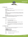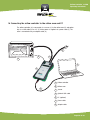
1
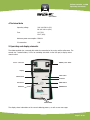
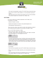
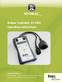
Reflow Controller V3 PRO
Operating Instructions
www.beta-eSTORE.com
Beta LAYOUT Ltd. • Bay 98 • Shannon Free Zone, Co. Clare • Ireland
Telefon + 353 (0) 61 70 11 70 • Fax + 353 (0) 61 70 11 65
Reflow Controller V3 PRO
Operating Instructions
Contents
1 General information .........................................................................................................................................4
1.1
Warranty und liability ...........................................................................................................................4
2 Safety ...................................................................................................................................................................................4
2.1 Intended use ................................................................................................................................................4
2.2 Safety instructions .................................................................................................................................5
3 Introduction ....................................................................................................................................................................6
4 Technical data ..........................................................................................................................................................7
5 Operating and display elements............................................................................................................7
6 Self-test ............................................................................................................................................................................9
7 Operating modes/soldering .....................................................................................................................9
7.1
Appropriate oven ......................................................................................................................................9
7.2 Preparing the oven ...............................................................................................................................10
7.3 Learning the oven characteristics .......................................................................................11
7.4 Reflow soldering .........................................................................................................................................12
8 Setting parameters via the display ...........................................................................................14
8.1 Switching the controller to parameterisation mode .......................................14
8.2 Menu layout ..................................................................................................................................................15
8.3 Main menu .....................................................................................................................................................15
8.4 “Settings” menu ........................................................................................................................................15
8.4.1 Profiles ..................................................................................................................................................................16
8.4.2 Using the parameters ..........................................................................................................................17
8.4.3 Preheat ..............................................................................................................................................................17
8.4.4Soak ........................................................................................................................................................................18
Page 2 of 39
Reflow Controller V3 PRO
Operating Instructions
8.4.5Reflow ...................................................................................................................................................................19
8.4.6Dwell ...................................................................................................................................................................20
8.5 “Base values” menu .........................................................................................................................2 1
8.5.1 Automatic phase extension ......................................................................................................21
8.5.2Temperature calibration ...............................................................................................................22
8.5.3Setting the measurement unit “Temperature” ...................................................23
8.5.4Setting background brightness ...........................................................................................23
8.5.5Restoring default values ..............................................................................................................24
9 Setting parameters via the computer .................................................................24
9.1 Connecting to the computer ...................................................................................................24
9.2 Installing the USB driver ...............................................................................................................25
9.3 Interface parameters .......................................................................................................................26
9.4 Terminal program .................................................................................................................................26
9.5 Communication test ..........................................................................................................................27
9.6 General commands ............................................................................................................................28
9.7 Commands for parameter setting and calibration .........................................30
9.8 Manual operation ..................................................................................................................................32
10 Software update instructions .........................................................................................................34
11 Error messages ................................................................................................................................................ 37
12 Maintenance and disposal ...................................................................................................................37
13 Guarantee.....................................................................................................................................................................38
14 Connecting the reflow controller to the reflow oven and PC ..................39
Page 3 of 39
Reflow Controller V3 PRO
Operating Instructions
1 General information
Please read this guide carefully prior to using the reflow controller as it contains important information on the functions, operation and maintenance of the product. Note:
This documentation is based on the product knowledge available at the time of manufacture. The accuracy and completeness of the work in question cannot be guaranteed. Technical changes for product advancement are excluded. This documentation
and the information it contains are subject to copyright and cannot be reproduced
either in full or in part or distributed to third parties without the written consent of the
publisher.
1.1 Warranty and liability
Our “General sales and delivery conditions” are always applicable. Beta LAYOUT excludes any warranty or liability claims for personal and material damages caused by one or more of the following:
• inappropriate use,
• incorrect assembly, setup or operation, • failing to observe information, requests or warnings in the operating instructions,
• unauthorised structural modifications to the equipment,
• improperly carried out maintenance or repairs.
Any damage caused by failing to follow the operating instructions will render the guarantee/warranty null and void. We accept no liability for consequential damages arising from
the above.
2 Safety
2.1 Intended use
This product can only be used to control a reflow soldering oven.
Using it for any purpose other than the above will lead to product damage, and inappropriate use is also associated with hazards such as short circuits, fire, electric shock etc.
The product must not be changed or modified in any way.
This product complies with all legal, national and European requirements. All company names and product designs are trademarks of the respective owners.
All rights reserved.
Please refer to the controller operating instructions manual, which is available for download
as a pdf on www.beta-eSTORE.com/RKCV3
Page 4 of 39
Reflow Controller V3 PRO
Operating Instructions
2.2 Safety instructions
Any damage caused by failure to follow the operating instructions will render the
guarantee/warranty null and void. We accept no liability for consequential damages.
We also accept no liability for material or personal damages caused by inappropriate
handling or failure to follow the safety instructions. In such cases, the warranty/guarantee is null and void.
•For safety and licensing (CE) reasons, unauthorised reconfiguration or modification of
the product is not permitted. Never disassemble the product.
•The product is designed for operation through the public mains supply only
(230V~/50Hz) and must be properly earthed. Plug the controller into a regulationcompliant earth socket.
•This product is not a toy and is not intended for use by children. Operate and store
the product out of children’s reach. Children may attempt to insert objects into the
openings of the unit, risking fatal electric shock.
•The product is only suited to dry indoor areas and must not get damp or wet. Never
use the product outdoors or in damp or humid conditions, and never handle it with
damp or wet hands. This could lead to fatal electric shock.
•The product must always be operated under supervision.
•Due to the risk of fire or explosion, the product should not be operated in any environment that is or may be exposed to flammable gases, fumes or types of dust.
•This product is intended for private use only and not for commercial use. •The product is only intended to regulate a soldering or reflow oven and should not be
connected to any other devices.
•The product only isolates one pole of the socket on the connection cable from the
mains. Even if the product is switched off, mains voltage may still be present around
the socket and the connected device.
•Do not use the product as a “circuit breaker” for the connected device.
•Before connecting the product to a PC, you must unplug it from the mains socket.
•Handle the product with care as it can be damaged by impact or as a result of falling
from even low heights.
•Do not continue to use the product if the product housing gets damaged. If it is still connected to the mains, do not touch it or any other attached devices. First, break off the
electrical circuit to which the product is connected (switch off the automatic circuit breaker).
You can now unplug the attached device and remove the controller from the mains socket.
Then bring the product to a repair workshop or dispose of it in an environmentally appropriate way.
• Dispose of packaging carefully as it could be dangerous in the hands of children. • If you are concerned about the functioning, operation or safety of the product, consult a specialist. Do not work on the product yourself. Page 5 of 39
Reflow Controller V3 PRO
Operating Instructions
3 Introduction
The reflow controller controls your reflow oven kit. To get the best soldering result,
specified times and temperatures must be maintained when soldering SMD components
using solder paste. The reflow controller regulates your reflow oven in such a way that times and temperatures are maintained and the optimum soldering result is achieved. The boards and components are heated gradually during a preheat phase in order to
avoid mechanical stress in those elements.
Following the preheat phase, the temperature is raised to just below the soldering temperature. In this way, the volatile components of the solder paste can escape with no
blistering. The oven is then heated to the soldering temperature. The solder paste liquefies and the
components adhere to the board. The temperature is kept stable during the soldering
process in order to avoid damage through overheating.
The controller beeps to signal the end of the soldering phase.
The soldered board can now be removed from the oven.
You can adapt the solder curves to your own requirements. Up to five different curves can be stored in the reflow controller.
Page 6 of 39
Reflow Controller V3 PRO
Operating Instructions
4 Technical data
Operating voltage: 230 V/AC 50 Hz (EU)
110 V/AC 60 Hz (USA)
Fuse: 8A-T (EU) 15A-T (USA)
Maximum power consumption: 1500 W
PC connection: USB
5 Operating and display elements
The reflow controller has a console with cables for connection to the mains and the reflow oven. The
console has 7 control buttons, 2 LEDs for controlling data traffic via the USB port, a display and an
acoustic alarm.
Sensor connection
ON/OFF power switch
Display
STOP button
START button
UP button
LEFT button
RIGHT button
OK button
DOWN button
Control LEDs
The display shows information on the current soldering process, as well as error messages.
Page 7 of 39
Reflow Controller V3 PRO
Operating Instructions
Operating elements
ON/OFF power switch
The reflow controller can be switched on and off using the power switch. We recommend that you end the current soldering process before switching off the power, or
alternatively, interrupt it using the STOP button
START button
Starts the soldering process. When the controller is first started, START initiates the
learn function for the oven.
STOP button
Interrupts the current soldering process.
OK button
Confirms previous settings and also brings you to the settings menu.
UP button
Increases setting values and also brings you to the previous item in a menu.
DOWN button
Decreases setting values and also brings you to the next item in a menu.
RIGHT button
Selects the next element at the same menu level.
LEFT button
Selects the previous element at the same menu level.
Display elements
Control LEDs
The LEDs display the data traffic on a connected PC. If no PC is connected, the LEDs
are not significant.
Display
The display shows all relevant information regarding your reflow controller. It is structured
as follows:
Number of active
parameter sets
Current status
Current phase
STATUS
PHASE
N xxxC
yyyS
Time elapsed
Temperature
Measurement unit
Temperature
Measurement unit
Time
Page 8 of 39
Reflow Controller V3 PRO
Operating Instructions
6 Self-test
When the controller is switched on, it runs a system test.
• Display test
The version number of the software will appear on the screen for around one second.
Please have this number ready in the event of any support queries.
• Sensor test
A temperature sensor check is done to determine whether a sensor is attached and if
so, to ensure it is isolated from the mains.
If no sensor is found or the sensor is giving an error message, the display will show the
status “Error” followed by “Sensor”.
If this error is displayed, please check the sensor and ensure it is attached correctly. The
error message will disappear as soon as the controller finds a correctly attached sensor.
• Buzzer test
The acoustic alarm is activated for one second.
The first time the controller is switched on or following a software update, the error message ‘Learn’ will be displayed after the self-test.
This indicates that the controller has not yet learned the oven characteristics and is not
ready for operation. A learn cycle must be carried out.
Error
Learn
xxxC
7 Operating modes/soldering
7.1 Appropriate oven
Please note that specific characteristics must be set for every oven type. In general, the
following capacity limits apply for reflow ovens:
Europe: 220..240 V~ / 8 A, 50 Hz
USA:
110 V~ / 15 A, 60 Hz
Maximum power consumption: 1500 W
Higher oven capacity than the above is not supported and will destroy the controller.
Page 9 of 39
Reflow Controller V3 PRO
Operating Instructions
Please note that the oven must be able to build up to the temperature required for the
soldering process. If the oven capacity is too low, it heats too slowly and this may expose the components to more thermal stress.
Please note the maximum temperature resistance of the sensor.
Note on using fan (convection) ovens:
Fan ovens should not be used because when the heat and fan functions are controlled
simultaneously, the resulting air movement causes ‘hot spots’ in the oven, which can
lead to significant temperature fluctuations. 7.2. Preparing the oven
Before you start soldering, you must prepare the oven and the temperature sensor.
• Connect the supplied sensor to the reflow controller, taking care to maintain correct polarity. • Run the sensor cable into the soldering area of the oven. • Secure the sensor in such a way that the end of it is as close as possible to the soldering material.
TIP ttach the temperature sensor to a segment of board using a wire and place it along-
A
side the board to be soldered. The board segment should have specifications identical to the board to be soldered.
The sensor supplied is heat-resistant up to 260 °C (500 °F).
Please ensure that your oven does not exceed the above temperature. Please ensure also that the sensor cable does not come in contact with oven parts that
may be hotter than 260 °C.
• Connect the mains plug of your reflow oven to the controller socket.
• Switch your reflow oven to the highest heat capacity.
• Switch the upper and lower heat on and slide the grill into the middle of the oven.
• Switch the oven temperature regulator to the highest setting.
• Set the oven timer to > 30 minutes. The oven should not be preheated
Page 10 of 39
Reflow Controller V3 PRO
Operating Instructions
7.3 Learning the oven characteristics
Before the oven can be used for soldering, the controller has to learn its heat and temperature characteristics. This is necessary before first use and after every software update at least.
The learned values are stored in the controller and used for all subsequent soldering
processes. However, you can repeat the learn process as often as you wish.
The controller always uses the results of the most recent learn event.
The message “Error learn“ on the display indicates that the learn phase has to be run
and the controller is not yet ready for soldering. When you see this message, start the learn process by pressing START.
You can also start the learn phase at a later time, as follows:
•Connect the oven and temperature sensor according to the instructions and switch on the controller.
•After the self-test, please wait until the oven is heated to a just below 50 °C.
•Now press OK once and the message “Setup” will appear on the display. Press OK again and press “Down” while the message “Setup” is still present (around 2 seconds).
“Learn” will now appear in the bottom line of the display. Press OK to start the learn process. Please wait until the learn process is fully complete and do not interrupt it. The controller is only ready to use when the learn process is complete and the oven is at just below 50 °C.
• The learn process requires a board to be placed in the oven and the temperature sensor
positioned under or over the board in such a way that they make contact with each other.
This will ensure that the temperature sensor measures the board temperature and not
the air temperature. • Close the oven and start the learn process as described above.
During the learn process, the “Learn” status is displayed, with information on each phase of the process. Page 11 of 39
Reflow Controller V3 PRO
Operating Instructions
The oven is now heated to 100 °C. Once it reaches this temperature, the heat is
switched off. The controller now measures how much more the oven will heat despite the heat being off. A beep signals the end of the learn process and the display indicates the “Cooling” phase. • The oven door can now be opened. The controller has now calculated and stored the oven’s characteristics. When the oven has cooled to below 50 °C, it is ready for reflow soldering.
7.4 Reflow soldering
The reflow controller works by taking control of the oven. It uses one of 5 possible parameter sets for the reflow process.
In this way, you can define parameter sets for different soldering processes. Please select the required parameter set before starting the soldering process.
Chapter 9, “Setting parameters via the computer”, contains further information on how
to change the active parameter set. The number of the currently selected parameter set is shown on the display.
Ready
2 125C
The soldering process can only be started when the reflow oven has been heated to
< 50 °C. If you want to solder several boards in quick succession, the oven temperature
must drop to below 50 °C between each soldering operation.
To solder the board, position it in the middle of the grill. Place the temperature sensor
under or over the board in such a way that it makes contact with the board. This ensures that the sensor will calculate the board temperature and not the air temperature.
Close the oven door and check again that the temperature sensor has not slipped away
from the board.
Press START to begin the automatic soldering process.
Solder
Soak
2 320F
20S
Page 12 of 39
Reflow Controller V3 PRO
Operating Instructions
Information on each soldering phase is shown on the display, as follows:
Operating mode
Active phase
Active parameter set
Temperature in oven
C measurement unit: F measurement unit:
Duration of phase
Solder
Preheat
Soak
Reflow
Dwell
Cooling
0 ... 4
xxx
C
F
Indicates that a soldering operation is in process.
Heats the oven slowly and keeps the temperature constant for a period of time.
Activates the solder paste. Continues to heat slowly until the solder paste is just below
melting point.
Continues to heat fast until the solder paste reaches melting point.
Maintains the temperature just over the melting point of the solder paste.
Cools the reflow oven. You can now open the door. The soldering process is complete and the
soldered material can be removed from the oven.
Number of the active parameter set
Measured oven temperature in the set measure-
ment unit
Temperature is displayed in Celsius °C
Temperature is displayed in Fahrenheit °F
Elapsed time of the current phase in seconds
When the soldering process is complete, “Cooling” is displayed as the active phase and
the controller beeps. The oven door must now be opened to allow the oven to cool
rapidly.
Warning: The board is still hot.
The automatic soldering process can only be activated when the controller has
learned the oven characteristics at least once.
Page 13 of 39
Reflow Controller V3 PRO
Operating Instructions
8 Setting parameters via the display
In general, there are two ways to set parameters in the controller: via the integrated
keyboard or via a connected PC. This chapter explains how to set parameters via the
integrated keyboard.
8.1 Switching the controller to parameterisation mode
The controller is switched to parameterisation mode as follows:
• Press OK and “Setup” will appear in the display
Setup
• Release OK and the display will remain the same.
• Press OK again within 3 seconds and hold for five seconds. A dash will appear in the top line for every second that has elapsed.
Setup
---
• After the fifth dash, the controller switches to “Setup” mode.
Setup
Ready
You can now switch between menu items using the UP and DOWN buttons. The next
chapter contains details on the menu layout.
Page 14 of 39
Reflow Controller V3 PRO
Operating Instructions
8.2 Menu layout
The controller has three different menus.
Main menu
When the controller is switched on, you are in the main menu. From the main menu, you
can start a soldering process or a learn cycle.
Settings
You can go to the “Settings” menu by switching the controller to parameterisation mode
(see previous chapter). In this menu, you can make all the parameter changes necessary
for your soldering process.
Base values
You can get to the “Base values“ menu via the “Settings” menu. In the “Base values”
menu, you can adapt controller performance to your own requirements. Aside from the
initial setup, no changes are usually required in this menu.
8.3 Main menu
The main menu contains the following menu items:
Ready
“Normal“ controller operation.
Pressing START will initiate a soldering cycle.
Setup
Entry point to the “Settings” menu. See chapter “Switching the controller to parameterisation model” for further information.
Learn
Initiates a learn cycle. Press START to begin a cycle. See chapter “Learning the oven characteristics“ for further information on the learn procedure and how to use it.
8.4 “Settings” menu
You are in the “Settings” menu when the status “Setup” appears in the first line of the
display and the current menu item is on the second line.
Setup
Preheat
The “Settings” menu contains the following menu items:
Ready
Menu exit point. Press OK to return to the main menu.
Profile
Active parameter set selection
Page 15 of 39
Reflow Controller V3 PRO
Operating Instructions
Preheat
“Preheat” phase settings for the active parameter set
Soak
“Soak” phase settings for the active parameter set
Reflow
“Reflow” phase settings for the active parameter set
Dwell
“Dwell” phase settings for the active parameter set
Base values Entry point to the “Base values” menu.
Press OK to access the “Base values” menu.
You can use UP or DOWN to navigate to the last or next menu item, respectively. If you want to change the settings in a menu item, scroll to the item using UP/DOWN, then press OK.
8.4.1 Profiles
You can use this menu item to activate one of the five parameter sets stored in the
device, as follows:
• Select the menu item “Profiles” in the “Settings” menu. See chapter “Settings” for
more information. When “Profiles” is selected, the number of the active profile will be
displayed in the bottom line.
Setup
Profile
0001
• Pressing OK will activate the menu item and the number of the active parameter set
will start to flash.
• You can change the value as required using the UP and DOWN buttons.
• Press OK to confirm.
Page 16 of 39
Reflow Controller V3 PRO
Operating Instructions
8.4.2 Using the parameters
Entry Parameter
Select next
parameter
Set parameter
Select next
parameter
Exit
When you have set all the parameters as required, press OK to confirm the settings. Please note that pressing OK always ends parameter input, even if not all parameters have yet been
changed. You are now back in the “Settings” menu.
8.4.3 Preheat
This menu item allows you to change the parameters for the “Preheat” phase. The parameters are as follows:
• Duration of the phase in seconds
• Required end temperature of the phase in the specified temperature unit
• Oven capacity during the phase in %
Please note that the settings always affect the currently active parameter set. Information on switching the active parameter set can be found in the chapter “Profiles”.
You can set the ‘Preheat’ parameters as follows:
• Select the menu item “Preheat” in the “Settings” menu. The chapter “Settings” contains further details. In the menu item “Preheat”, the num-
ber of the active parameter set is also displayed in the first line.
Setup
Preheat
•
4
Pressing OK will activate the menu item. You will now see the name of the activated menu item (Preheat) and the number of the current parameter set on the display. The second line shows the name of the selected parameter to be changed and its current value, which will flash onscreen.
This means that the value can be changed using UP/DOWN.
Page 17 of 39
Reflow Controller V3 PRO
Operating Instructions
Preheat
temp:
4
0125C
• Set parameters.
• Then select the next parameter using the LEFT or RIGHT button and make the change.
•
When you have set all the “Preheat” parameters, you can end parameter input by pressing OK.
lease note that pressing OK always ends parameter input, even if not all parameters P
have yet been changed. You are now back in the “Settings” menu.
8.4.4 Soak
This menu item allows you to change the parameters for the “Soak” phase. The parameters are as follows:
• Duration of the phase in seconds
• Required end temperature of the phase in the specified temperature unit
• Oven performance during the phase in %
Please note that the settings always affect the currently active parameter set. Information on switching the active parameter set can be found in the chapter “Profiles”.
You can set the “Soak” parameters as follows:
• Select the menu item “Soak” in the “Settings” menu. The chapter “Settings” contains further details. In the menu item “Soak”, the number of the active parameter set is also displayed in the first line.
Setup
Soak
2
• Pressing OK will activate the menu item. You will now see the name of the activated
menu item (Soak) and the number of the current parameter set on the display. The
second line shows the name of the selected parameter to be changed and its current
value, which will flash onscreen.
This means that the value can be changed using UP/DOWN.
Soak
time:
2
0090s
• Set parameters.
Page 18 of 39
Reflow Controller V3 PRO
Operating Instructions
• Then select the next parameter using the LEFT or RIGHT button and make the change.
• When you have set all the “Soak” parameters, you can end parameter input by pressing OK.
Please note that pressing OK always ends parameter input, even if not all parameters
have yet been changed. You are now back in the “Settings” menu.
8.4.5 Reflow
This menu item allows you to change the parameters for the “Reflow” phase.
The parameters are as follows:
• Duration of the phase in seconds
• Required end temperature of the phase in the specified temperature unit
• Oven performance during the phase in %
Please note that the settings always affect the currently active parameter set. Information on switching the active parameter set can be found in the chapter “Profiles”.
You can set the “Reflow” parameters as follows:
• Select the menu item “Reflow” in the “Settings” menu. The chapter ‘Settings’ contains further details. In the menu item “Reflow”, the number
of the active parameter set is also displayed in the first line.
Setup
Reflow
2
• Pressing OK will activate the menu item. You will now see the name of the activated
menu item (Reflow) and the number of the current parameter set on the display. The second line shows the name of the selected parameter to be changed and its current value,
which will flash onscreen. This means that the value can be changed using UP/DOWN.
Reflow
power:
2
080%
• Set parameters.
• Then select the next parameter using the LEFT or RIGHT button and make the change.
• When you have set all the “Reflow” parameters, you can end parameter input by pressing OK.
Please note that pressing OK always ends parameter input, even if not all parameters
have yet been changed. You are now back in the “Settings” menu.
Page 19 of 39
Reflow Controller V3 PRO
Operating Instructions
8.4.6 Dwell
This menu item allows you to change the parameters for the “Dwell” phase. The parameters are as follows:
• Duration of the phase in seconds
• Required end temperature of the phase in the specified temperature unit
• Oven performance during the phase in %
Please note that the settings always affect the currently active parameter set. Information on switching the active parameter set can be found in the chapter “Profiles”.
You can set the “Dwell” parameters as follows:
• Select the menu item “Dwell” in the “Settings” menu. The chapter “Settings” contains further details. In the menu item “Dwell”, the number of the active parameter set is also displayed in the first line.
Setup
Dwell
1
• Pressing OK will activate the menu item. You will now see the name of the activated
menu item (Reflow) and the number of the current parameter set on the display. The
second line shows the name of the selected parameter to be changed and its current
value, which will flash onscreen.
This means that the value can be changed using UP/DOWN.
Dwell
1
power: 070%
• Set parameters.
• Then select the next parameter using the LEFT or RIGHT button and make the change.
• When you have set all the “Dwell” parameters, you can end parameter input by pressing OK. Please note that pressing OK always ends parameter input, even if not all parameters
have yet been changed. You are now back in the “Settings” menu.
8.5 “Base values” menu
You can get to the “Base values” menu by switching the controller to parameterisation
mode (see chapter “Switching the controller to parameterisation mode”) and activating
Page 20 of 39
Reflow Controller V3 PRO
Operating Instructions
the menu item “Base values” in the “Settings” menu (see chapter “Settings”). You are in
the “Base values” menu when you can see the status “Base values” in the first line of
the display and the current menu item in the second line.
Base Values
Ready
The “Base values” menu contains the following menu items:
Ready
Menu exit point. Press OK to return to the main menu.
Autoextend
Automatic phase extension On/Off
TempOffset
Temperature calibration/Sensor error adjustment
TempUnit
Temperature unit settings °C / °F
Factory Default Resets all values to default
You can use UP or DOWN to navigate to the last or next menu item, respectively. If you want to change the settings in a menu item, scroll to the item using UP/DOWN,
then press OK.
8.5.1 Automatic phase extension
Automatic phase extension involves extending a soldering phase beyond the set phase
duration if the target temperature was not reached in the set time.
This is necessary if, for example, you are not familiar with the heat performance of the
oven and first want to test how long it takes for the oven to reach the target temperature using the specified performance settings. You can switch the “Autoextend” function
on or off.
Autoextend ON:
This allows a soldering phase to be extended until the oven is heated to the set end
temperature for that phase. If the end temperature is reached within the given time, the
phase is not extended.
AutoExtend OFF:
When the set phase duration is complete, the next phase starts regardless of whether
the phase end temperature was reached.
You can change the “Autoextend” function as follows:
• Go the “Base values” menu (see chapter “Base values”).
• Select the menu item “Autoextend”. The current setting is shown in the display.
Page 21 of 39
Reflow Controller V3 PRO
Operating Instructions
Base Values
Autoextend
OFF
• Pressing OK will activate the menu item and the text showing the current setting will
start to flash.
• The UP and DOWN buttons can be used to change the value as required.
• Press OK to confirm.
8.5.2 Temperature calibration
The temperature sensor for the reflow controller is preset and generally does not need
to be calibrated. However, if required, the reflow controller can be synchronised with the
sensor. You can set temperature calibration as follows:
• Go to the “Base values” menu (see chapter “Base values”).
• Select the menu item “TempOffset”. The display shows the current setting of this value in the selected temperature unit.
Base Values
TempOffset
10F
• Pressing OK will activate the menu item and the value to be adjusted will start to flash.
• The UP and DOWN buttons can be used to change the value as required.
Press OK to confirm.
User diagram for sections 8.5.1 “Automatic phase extension” and
8.5.2 “Temperature calibration”
Page 22 of 39
Reflow Controller V3 PRO
Operating Instructions
8.5.3 Setting the measurement unit “Temperature”
You can set the measurement unit for the temperature in your reflow controller by selecting one of the following:
C: Temperature unit °C (Celsius) F: Temperature unit °F (Fahrenheit)
Please note that when you switch temperature units, the change only happens in the
display. Internally, the controller always calculates in °C. This ensures that your temperature profiles and settings will not be corrupted when you change temperature units. The temperature measurement unit can be changed as follows:
• Go the “Base values” menu (see chapter “Base values”).
• Select the menu item “TempUnit”. The current value for this setting is shown in the display.
The symbols “F” and “C” stand for Fahrenheit ° F and Celsius ° C, respectively.
• Pressing OK will activate the menu item and the temperature unit symbol will start to
flash.
• The UP and DOWN buttons can be used to change the value as required.
Press OK to confirm.
8.5.4 Setting the background brightness
The display brightness of your reflow controller can be adapted to individual requirements. There are 11 levels of brightness, from
0 Display brightness off
to
10 Maximum display brightness
The default value is 5. Please note that if the brightness level is too high, users may
have difficulty reading the display.
Background brightness can be changed as follows:
• Go to the “Base values” menu (see chapter “Base values”).
• Select the menu item “Backlight”. The current value for this setting will be shown in
the display. Base Values
Backlight
0005
Page 23 of 39
Reflow Controller V3 PRO
Operating Instructions
• Pressing OK will activate the menu item and the current brightness value will start to
flash.
• You can change the value as required using the UP and DOWN buttons. The change
to the brightness level takes effect immediately and the display will change to the new
setting.
• Press OK to confirm.
8.5.5 Restoring default values
This menu item is used to reset all controller settings to the factory default, as follows:
• Go to the “Base values” menu (see chapter “Base values”).
•Select the menu item “Factory Default”.
Base Values
Factory Default
• Pressing OK will activate the menu item and a security question will appear on the
display.
Factory Default
OK to Reset
• Pressing OK will reset the values. Pressing UP will deactivate the menu item and the values will not be reset.
9 Setting parameters via the computer
9.1 Connecting to the computer
The reflow controller has a USB port which enables it to be connected to a PC or Notebook.
You can also update the reflow controller software via the USB port.
When you attach the USB cable, a new serial interface will be available. Further details
can be found in the section on the USB driver. You can set controller parameters using this serial interface in the same way as using
the display. Other data such as status and diagnostic information can also be output
and logged for quality assurance purposes.
Page 24 of 39
Reflow Controller V3 PRO
Operating Instructions
9.2 Installing the USB driver
Depending on the operating system, it may be necessary to install driver software. The
reflow controller uses a standard FTDI USB serial converter chip.
An up-to-date LINUX system does not require a driver as it will recognise the USB chip
and allocate a port /dev/ttyUSB0. If you already have another USB serial converter in
your system, the multiplexer will connect to port /dev/ttyUSB1 or port /dev/ttyUSB2.
Driver software may need to be installed on a Windows system. Drivers for this chip are
available on www.beta-eSTORE.com/RKCV3 and on the website of the FTDI manufacturer (http://www.ftdichip.com/FTDrivers.htm). If you have a different device on your PC
with an FTDI USB serial chip, the driver is already available. The most recent Windows
systems include the driver in the installation.
Alternatively, you can download the driver from the manufacturer’s home page and configure it according to the installation instructions. When the driver has been installed successfully, the operating system automatically
assigns a virtual serial interface (COM port) to the USB. You can control this in the
device manager and also modify the serial interface number as required. You will find the
settings for your virtual port in the device manager under “Ports (COM & LPT)”.
COM port allocation
Page 25 of 39
Reflow Controller V3 PRO
Operating Instructions
Please note the following:
To make software updates easier, the USB chip uses voltage from the connected
computer.
This means that the device is attached to your computer as soon as you connect the
USB cable, regardless of whether or not the reflow controller is connected to the mains. The virtual COM port will remain in place for as long as the connection to the controller
is physically available, regardless of whether or not the reflow controller is connected to
the mains.
Data communication from the PC to the controller is only possible when the controller is
also switched on.
If you wish to connect the reflow controller to various USB ports on your computer, the
operating system must carry out a new driver installation each time and assign a new
virtual COM port if necessary. This is a feature of Windows operating systems which we cannot control. To make it
less inconvenient, we recommend that you always connect the controller to the same
USB socket or alternatively, use a different operating system.
In Linux operating systems, the virtual port is always on /dev/ttyUSB0, or if you are
using other devices, on the next ‘free’ ttyUSB. This is the case regardless of what USB
port you are using on your computer. 9.3 Interface parameters
To communicate with the reflow controller, set the following parameters for your terminal
program:
•
•
•
•
•
9600 baud
8 data bits
no parity
1 stop bit
no handshake.
9.4 Terminal program
You can use any terminal program to communicate with the controller.
See below for examples of suitable terminal programs that are free of charge:
Windows: Hyperterminal
Linux: Miniterm
Page 26 of 39
Reflow Controller V3 PRO
Operating Instructions
9.5 Communication test
Connect the controller to the computer as described above, start your terminal program
and then switch on the controller.
When the controller has been successfully connected to your PC, you will see the startup message below.
You can now manage the controller via the serial interface. You can also do this at any
time using the integrated keyboard, even if your PC is still connected.
Page 27 of 39
Reflow Controller V3 PRO
Operating Instructions
9.6 General commands
You can use the following commands via the PC interface:
Command
Parameter
Definition
help
Lists all commands
tempshow
[0..254]
The measured temperature is displayed continually at second intervals specified by the parameter:
tempshow 5<enter>
displays the current temperature every 5 seconds.
tempshow 0<enter>
switches off temperature display.
tempshow<enter>
displays the current temperature once.
The display format is as follows:
phase, seconds, +xxx, unit
The data elements are separated with a comma. If you store the data sets in your terminal program, they can then be entered easily as .csv (comma-
separated values) into table processing programs such as Open Office.
If the command has no parameters, the current temperature is only displayed once.
temptrace
debug
[0..254]
The measured temperature is displayed at second intervals specified by the parameter but only du-
ring a soldering process.Otherwise this command is the same as “tempshow”.
[0..1]
Display internal debug information
Example: Off, 31, +058, C or
Off, 31, +136, F
debug 1<enter>
Switch on debug information
debug 0<enter>
The form and content of status messages may change in the case of program updates.
Page 28 of 39
Reflow Controller V3 PRO
Operating Instructions
Command
Parameter
Definition
trace
[0..1]
Display internal status messages
trace 1<enter>
Switch on status message display
trace 0<enter>
Switch off status message display
tempUnit
The form and content of status messages may change in the case of program updates. Setting the temperature unit
tempUnit C<enter> Temperature unit is °C
tempUnit F<enter> Temperature unit is °F
If the temperature unit is changed, the stored tem-
perature profiles are kept, i.e., changing the tempe-
rature unit will not change the temperature status or soldering result.
bLight
[0..10]
Setting the display background brightness.
bLight 5<enter>
sets brightness to medium. The value “0” switches off brightness.
showall
Lists all set parameters.
settings
[0..4]
Selects a parameter set as active. All soldering operations will be carried out using those
parameters.
settings 3<enter>
All soldering operations will be carried out using the stored parameter set 3.
doStart
Equivalent to START
doStop
Equivalent to STOP
doOk
Equivalent to OK
doLeft
Equivalent to LEFT
doRight
Equivalent to RIGHT
doUp
Equivalent to UP
doDown
Equivalent to DOWN
Page 29 of 39
Reflow Controller V3 PRO
Operating Instructions
9.7 Commands for parameter setting and calibration
The reflow controller can be set for different solder pastes, different temperature sensors
and different oven types. The parameters necessary to make those settings are input
via the computer interface. Please ensure that all settings relate to the parameter set currently in use. You can store
up to 5 different settings (parameter sets) in the controller. In the case of all commands,
if the command has no parameters, the controller will display the value currently set.
Command
Parameter
Definition
phttemp
[0 .. 254] °C
[32 .. 490] F
End temperature of the preheat phase
phttime
[0 .. 65534] Sek. Duration of the preheat phase
phttemp 125<ENTER>
sets the temperature to 125 °C.
If the parameter is set to 0, the controller itself will define the duration of the “Preheat” phase.
The oven will be operated at the set capacity until the preset temperature has been reached.
phttime 180<ENTER>
sets the duration to 180 seconds.
phtpwr
[0 .. 100] %
Heat capacity of the preheat phase
phtpwr 60<ENTER>
Oven will operate at 60 % heat capacity.
soaktemp
[0 .. 254] °C
[32 .. 490] F
End temperature of the activation or soak phase
soaktime
[0 .. 65534] Sek. Duration of the activation phase
If the parameter is set to 0, the controller itself will define the duration of the “Soak” phase. The oven will be operated at the set capacity until the preset temperature has been reached.
soaktime 90<ENTER> sets the duration to
90 seconds.
soakpwr
[0 .. 100] %
Heat capacity of the activation phase
soakpwr 80<ENTER>
Oven will operate at 80 % heat capacity.
soaktemp 175<ENTER>
sets the temperature to 175 °C.
Page 30 of 39
Bedienungsanleitung
Reflow-Controller
Command
Parameter
Definition
reflowtemp
[0 .. 254] °C
[32 .. 490] F
End temperature of the reflow phase
reflowtime
[0 .. 65534] Sek. Duration of the reflow phase
If the parameter is set to 0, the controller itself will define the duration of the reflow phase. The oven will be operated at the set capacity until the preset temperature has been reached.
reflowtime 140<ENTER>
sets the duration to 140 seconds.
reflowpwr
[0 .. 100] %
Heat capacity of the reflow phase
reflowpwr 100<ENTER>
Oven will operate at 100 % heat capacity.
dwelltemp [0 .. 254] °C [32 .. 490] F
End temperature of the “Dwell” phase
dwelltime
[0 .. 65534] Sek. Duration of the “Dwell” phase
If the parameter is set to 0, the controller itself defines the duration of the “Dwell” phase. The oven will be operated at the set capacity until the preset temperature has been reached.
dwelltime 40<ENTER>
sets the duration to 40 seconds.
dwellpwr
[0 .. 100] %
Heat capacity of the “Dwell” phase
dwellpwr 80<ENTER>
Oven will operate at 80 % heat capacity.
tempoffset
[-30 .. 30] °C
[-54 .. 54] F
Adjusting the temperature sensor
reflowtemp 232<ENTER>
sets the temperature to 232 °C.
dwelltemp 232<ENTER>
sets the temperature to 232 °C.
This setting is universal and applies to all parame-
ter sets.
tempoffset -3<ENTER>
3 °C is deducted from the measured temperature.
The temperature less 3 °C is displayed.
tempoffset 5<ENTER>
5 °C is added to the measured temperature.
The temperature plus 5 °C is displayed.
Page 31 of 39
Reflow Controller V3 PRO
Operating Instructions
Command
Parameter
Definition
autoextend
[0 .. 1]
Controlling automatic soldering phase extension
autoextend 1<enter>
Switch on automatic soldering phase extension.
If the preselected end temperature for this phase has not been reached in the set time, the phase will be extended until the set temperature has been reached.
autoextend 0<enter>
Switch off automatic soldering phase extension.
When the set phase duration is complete, the next phase will start regardless of whether the preset temperature for the phase was reached.
mta
[0 ... 65534]
This parameter is universal and applies to all solder curves.
Controlling oven monitoring
mta 0<enter>
Switch off automatic oven monitoring.
mta X<enter>
X>0 Switch on automatic oven monitoring.
This command checks that the oven temperature has reached a level of at least X * 0.25 °C within 15 seconds. If this is not the case (e.g., due to a defective oven or the oven door not being closed fully), the soldering process is terminated and an error message displayed.
9.8 Manual operation
The operating mode “Manual operation” can only be controlled via the PC.
In effect, this operating mode allows you full access to the controller, which means you
can write your own controller programs on the PC.
You can also devise special profiles or applications, for example, “managed cooling” of
sintered tools. When the controller is in “Manual” mode, the message “Manual” will be shown in the
display line, along with the current temperature.
Page 32 of 39
Reflow Controller V3 PRO
Operating Instructions
The “Pulse” phase will appear in the last line of the display. In “Manual” mode, it is not
possible to use the keyboard or carry out normal soldering functions. Manual
Puls
75F
When a heat pulse is now released via the interface, the pulse capacity is displayed
simultaneously for exactly one second; so for example, a 50% pulse would be displayed
as follows:
Manual
Puls
75F
50%
In “Manual” mode, you can release single heat pulses via the serial interface using the
command “shot X”, where X indicates the required capacity in %.
A heat pulse always lasts for a second. You can use the parameter “Capacity” to determine for how long the heat is actually switched on during a heat impulse.
Example:
shot 10 --> 10 % capacity for 1 second --> Heating is on for 100 ms and off for 900 ms
shot 25 --> 25 % capacity for 1 second --> Heating is on for 250 ms and off for 750 ms
At the end of a heat pulse, the measured temperature is displayed via the interface in
the format “shot, seconds, +xxx, unit”.
Example: shot, 31, +058, C bzw.
shot, 31, +136, F
A period of 31 seconds has elapsed since the controller was switched on and the temperature measured was 58 °C. Data elements are separated by a comma, which makes
it easier to separate each value in the control program.
Please note that for safety reasons, the oven cannot be switched on permanently via the
interface. Every heat pulse takes exactly a second. If the connection to the control computer is lost, the oven will switch off in a second at most.
The “Shot” command can only be used under the following circumstances:
• The controller is in “Manual” operating mode.
• A previous heat pulse is completed.
Page 33 of 39
Reflow Controller V3 PRO
Operating Instructions
Command
Parameter
Definition
Manual
Switch controller to manual mode
Manual 0<enter> End manual mode,
controller is switched to normal mode.
Manual 1<enter>
Switch controller to manual mode.
shot
0 .. 100] %
Single pulse with heat capacity X
shot X<ENTER> Release single heat pulse X%.
WARNING!
This command will only work if the controller has already been switched to manual mode.
10 Software update instructions
The software can be updated via the controller’s USB interface. To do this, you will need
the following:
• A PC with a USB interface and Windows operating system.
• A standard USB cable.
• The software “Megaload” (available for download on www.beta-eSTORE.com/RKCV3).
Thanks to Sylvain Bissonette (www.microsyl.com), who kindly made this software available to us.
Start by unzipping the files into your designated directory.
The software can also be run directly from a host, in which case separate installation is
not required.
Connect the controller to the USB port on your PC. If you have not yet configured the
PC connection for the controller, please do so by following the instructions in the chapter
“Setting parameters via the computer”.
• Test the PC connection with an appropriate terminal program.
• Make a note of your own controller settings (parameter sets).
Page 34 of 39
Reflow Controller V3 PRO
Operating Instructions
• Close the terminal program and switch the reflow controller off.
• Start the program “Megaload.exe” and the following window will open:
• Set the parameters as shown in the diagram.
Please ensure that you only use the source files provided by us.
Please ensure that the checkbox “Eeprom programming” is always ticked.
Check again that you have made a note of your own parameter settings.
Check again that you have selected the correct files for programming.
• Power on the controller and programming will commence immediately.
It is important that you do not interrupt this process.
Page 35 of 39
Reflow Controller V3 PRO
Operating Instructions
• When the programming operation is finished, the controller will carry out a self-test.
The software update is then complete.
• End the program “Megaload”.
NOTE: It is important to ensure that you selected appropriate source files for the controller. For example, the boot loader program can recognise that no file was selected but
only after the software has been deleted in the controller
• Re-enter your selected settings.
Page 36 of 39
Reflow Controller V3 PRO
Operating Instructions
11 Error messages
The following error messages were generated by the controller and displayed on the
screen:
Error message
Cause
Solution
“Sensor” error The attached sensor was - Connect sensor
was not recognised or
- Replace sensor
is faulty..
“Too Hot” error The temperature sensor has detected that the tempera ture is too high to start a
new soldering process.
“Oven” error
The temperature in the oven has not reached the defined
preset value.
“Learn” error
Open oven and allow to cool down
Oven switched on?
Oven connected?
Oven door closed?
Power setting too low?
Minimum temperature increase incorrectly set
The oven characteristics have Start a learn procedure for the oven
not yet been learned.
12 Maintenance and disposal
The reflow controller is maintenance-free. The mains fuse should only be changed by a qualified specialist and the replacement
fuse should have the same technical specifications. The use of repaired fuses and the
practice of bridging fuses are not permitted. Repairs should only be carried out by an authorised specialist. Used electronic devices are recyclable and should not be disposed of with household
refuse. The device must be disposed of at the end of its life according to the appropriate legal
guidelines.
These instructions represent an accurate technical description at the time of going to press.
Subsequent changes in technology or configuration are reserved.
Page 37 of 39
Reflow Controller V3 PRO
Operating Instructions
13 Guarantee
We give a one-year guarantee on this device. The guarantee covers free correction of
defects that do not result from using faulty materials or from manufacturing defects (proof
required). Further claims are excluded. We offer no guarantee and accept no liability for damages or consequential damages
in connection with this product. We reserve the right to repair, improve, part-deliver, or
refund the purchase price.
In the following circumstances, no repair will be offered or the guarantee will be rendered
null and void:
•Changes or attempted repairs to the device, or unauthorised modification of the circuitry
• Overloading the assembly components
• Damages caused by third parties
•Damages caused by failure to observe the operating instructions and connection diagram • Connection to an inappropriate voltage or current type
•Faulty operation or damage caused by negligent handling or misuse
•Defects caused by bridged fuses or by using the wrong fuse type
In all cases above, product return is at your own expense.
Page 38 of 39
Reflow Controller V3 PRO
Operating Instructions
14 Connecting the reflow controller to the reflow oven and PC
The reflow controller (A) is connected via a sensor (C) to the reflow oven (B) and optionally via a USB cable (D) to a PC (E). Mains power is supplied via a power cable (F). The
oven is connected using an adapter cable (G).
F
G
C
B
E
A
A Reflow controller
B Reflow oven
D
C Sensor
D Optional USB cable
E
PC (optional)
F
Power cable
G Adapter cable
Page 39 of 39
Reflow Controller V3 PRO
Safety instructions
Intended Use
This product can only be used to control a reflow soldering oven.
Using it for any purpose other than the above will lead to product
damage, and inappropriate use is also associated with hazards such as
short circuits, fire, electric shock etc. The product must not be changed
or modified in any way.
All company names and product designs are trademarks of the respective owners. All rights reserved.
Please refer to the controller operating manual, which is available for
download as a pdf in the relevant product category on
www.beta-eSTORE.com/RKCV3
This product complies with all legal, national and European requirements.
Safety Instructions
Any damage caused by failure to follow the operating instructions will render the guarantee/warranty
null and void. We accept no liability for consequential
damages. We also accept no liability for material or
personal damages caused by inappropriate handling or
failure to follow the safety instructions. In such cases,
the warranty/guarantee is null and void.
• For safety and licensing reasons, unauthorised
reconfiguration or modification of the product is not
permitted. Never disassemble the product.
• The product is designed for operation through the public mains supply
only (230V~/50Hz) and must be properly earthed. Plug the controller
into a regulation-compliant earth socket.
• This product is not a toy and is not intended for use by children.
Operate and store the product out of children’s reach. Children may
attempt to insert objects into the openings of the unit, risking fatal
electric shock.
• The product is only suited to dry indoor areas and must not get damp
or wet. Never use the product outdoors or in damp or humid conditions, and never handle it with damp or wet hands. This could lead to
fatal electric shock.
• Before connecting the product to a PC, you must unplug it from the
mains socket.
• Handle the product with care as it can be damaged by impact or as a
result of falling from even low heights.
• Do not continue to use the product if the product housing gets damaged. If it is still connected to the mains, do not touch it or any other
attached devices. First, break off the electrical circuit to which the
product is connected (switch off the automatic circuit breaker). You can
now unplug the attached device and remove the controller from the
mains socket. Then bring the product to a repair workshop or dispose
of it in an environmentally appropriate way.
• Dispose of packaging carefully as it could be dangerous in the hands
of children.
• If you are concerned about the functioning, operation or safety of the
product, consult a specialist. Do not work on the product yourself.
Disposal
The device must be disposed of at the end of its life
according to the appropriate legal guidelines.
• The product must always be operated under supervision.
• Due to the risk of fire or explosion, the product should not be operated
in any environment that is or may be exposed to flammable gases,
fumes or types of dust.
• The product is intended for private use only and not for commercial
use.
• The product is only intended to regulate a soldering or reflow oven
and should not be connected to any other devices.
• The product only isolates one pole of the socket on the connection
cable from the mains. Even if the product is switched off, mains voltage
may still be present around the socket and the connected device.
• Do not use the product as a “circuit breaker” for the connected device.
Technical Data
Operating voltage:
230 V/AC 50 Hz (EU)
110 V/AC 60 Hz (USA)
Maximum power consumption: Fuse:
PC connection: 1500 W
8A-T (EU)
15A-T (USA)
USB