1
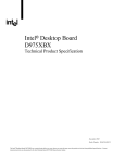
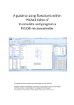
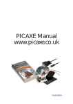
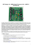
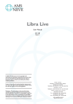
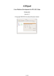
BOT120 PICAXE-20X2 MICROBOT
Microbot Overview
The BOT120 PICAXE 20X2 Microbot is a simple to
assemble kit that uses a unique design which requires no
soldering of wires to build and/or reconfigure a versatile
robot.
At the heart of the Microbot is a motherboard which
contains a powerful PICAXE 20X2 microcontroller which
can be programmed using flowcharts using the ‘Logicator
for PICAXE’ software or in the PICAXE BASIC language.
The Microbot can be programmed on Windows, Linux and
Mac computer systems. Programs are downloaded via the
AXE027 USB cable (purchase separately).
The Microbot motherboard is also fitted with a battery box, 2 motors to
create movement, a piezo sounder to make sounds, two LED ‘eyes’, a
push switch and a download socket for connecting the AXE027 USB
programming cable.
Various input/output modules can also be easily connected to the
motherboard via the unique patented ‘microbric edge’ and connector
'bric'. A ‘microbric edge’ consists of three conductors (+ V, 0V and Data).
The plastic bric is used to connect two ‘microbric edges’ together and
then clamping nut/bolts are used to complete the electrical connection
and to physically hold the assembly together.
The starter pack contains a number of modules including bumper, line
tracker, pen holder and a servo connector. Other sensor modules are
also available separately in ‘add-on packs’ – for instance the BOT121
sensors pack contain an infra-red sensor module to receive commands
from a TV style remote control, two LDR light sensor modules and an
infra-red transmitter module.
PICAXE Programming System
The ‘brain’ of the Microbot is a powerful PICAXE-20X2 microcontroller
that can be reprogrammed by the end user. Therefore the Microbot can
be easily customised and programmed with new features as required.
For futher details about using the PICAXE system please see the PICAXE
manuals, which are available as a free download from www.picaxe.co.uk
This manual includes side by side examples of both ‘PICAXE BASIC’ and
‘Logicator flowchart’ programs. Either can be used to program Microbot.
Microbot Power Supply
The Microbot is designed to run at 4.5V from 3 x AAA (LR03, 24A) size
batteries (not supplied). Good quality alkaline batteries are
recommended. Always ensure the batteries are connected the correct way
around and do not mix new and old, or different types, of batteries
together.
If the Microbot fails to operate or moves erratically try replacing the
batteries. Please dispose of old batteries by taking to a recycling centre.
revolution
(c) Copyright Revolution Education Ltd.
Web: www.picaxe.co.uk
1.1 04/10
BOT120.PMD
2
BOT120 PICAXE-20X2 MICROBOT
Contents
Microbot Overview
PICAXE Programming System
Microbot Power Supply
BOT120 Microbot Contents List
The Microbric Connector
Microbot -Fully Assembled Images
Assembly 1 – Motherboard Panel
Assembly 2 – Battery Box
Assembly 3 – Motor Housing
Assembly 4 - Motors
Assembly 5 - Wheels, Tyres and Rear Skid
Assembly 6 - Line Tracker
Assembly 7 – Bumper Switches
Assembly 8 - Pen Holder, Servo and SRF005 Modules
Fully Assembled Microbot
Motor Trouble Shooting
Programming Software
Programming Cable
Download Hard Reset
PICAXE-20X2 Pin Connections
PICAXE-20X2 Microbot Pinout Table (Logicator)
PICAXE-20X2 Microbot Pinout Table (Programming Editor / AXEpad)
Programming Example 1 - LED Eyes
Programming Example 2 – Push Button Switch
Programming Example 3 – Bumper
Programming Example 4 – Piezo Sounder
Programming Example 5 – Motors
Programming Example 6 – Line Tracker Testing
Programming Example 7 – Line Tracker Program
BOT121 Microbot Sensors Pack
Assembly 9 - Infra-red Receiver (IR RX) Module
Assembly 10 - Infra-red Transmitter (IR TX) Module
Using the TVR010A Infra-red TV Style Remote
Programming Example 8 – Infra-red Receiver
Programming Example 9 – Infra-red Transmitter
Assembly 11 - LDR Light Sensor Modules
Programming Example 10 – Testing LDR Light Sensors
Programming Example 11 – Light Follower
SRF005 Ultrasonic Range Finder
Assembly 12 - SRF005 Ultrasonic Range Finder
Programming Example 12 – Testing SRF005
Programming Example 13 – Using the SRF005
BOT123 Servo Upgrade Pack
Assembly 13 - BOT123 Servo / SRF005 Servo Adapter
Programming Example 14 – Using Servos
BOT122 Wheel Encoder Upgrade Pack
BOT127 Line Tracker / LED Upgrade Pack
Appendix 1 - Home Made Sensors
Appendix 2 - BOT120 Microbot Motherboard Schematic
Appendix 3 - BOT120 Sensors Schematic
Appendix 4 - BOT121 Sensors Pack Schematic
Appendix 5 - BOT123 Servo Pack Schematic
Appendix 6 - Advanced PIC (Non-PICAXE) Programming
Appendix 7 - Copyright and Trademarks
BOT110 Versabot - Microbot’s ‘big brother!’
revolution
(c) Copyright Revolution Education Ltd.
Web: www.picaxe.co.uk
1
1
1
3
4
5
6
7
7
8
10
11
13
15
15
16
17
17
18
18
19
20
21
22
23
24
25
28
29
30
32
32
33
34
35
36
36
37
39
39
40
41
42
43
43
45
46
47
48
48
49
49
50
51
51
Version 1.3 06/11
BOT120.PMD
3
BOT120 PICAXE-20X2 MICROBOT
BOT120 Microbot Contents List
BOT120
BOT120S
BOT120U
Microbot Pack (software free download)
Microbot Pack with AXE026 Serial Cable and software CD
Microbot Pack with AXE027 USB Cable and software CD
Qty
Description
Replacement
order code
1
PCB panel containing:
Microbot motherboard
Bumper Modules x 2
Line Tracker Module
Pen Holder Module
Servo Module PCB
Quarter Module PCB
SRF005 Module PCB
BOT120
BOT919
BOT127
BOT120
BOT123
BOT918
BOT120
2
Motors
BOT900
1
1
Battery Holder
Battery Base
BOT911
BOT910
2
2
2
Motor Housings
Axles
Wheels
BOT902
BOT903
BOT904
1
2
1
Bumper
Bumper connectors
Skid
BOT906
BOT907
BOT909
19
12
4
M2 hex head bolts
M2 domed nuts
14mm support posts
BOT125
BOT125
BOT126
2
2
2
2
Tyres
Bumper contact rubber (elastomer)
M3 battery mount bolts
M3 battery mount nuts
BOT905
BOT908
BOT920
BOT921
6
2
1
brics
worm gears
3 way straight header
BOT125
BOT901
CON035
1
1
Allen Key
tube grease
BOT124
BOT912
The full assembly instructions and program examples are
found in the Microbot manual which is a free download from:
http://www.rev-ed.co.uk/docs/bot120.pdf
revolution
(c) Copyright Revolution Education Ltd.
Web: www.picaxe.co.uk
Version 1.3 06/11
BOT120.PMD
4
BOT120 PICAXE-20X2 MICROBOT
The Microbric Connector
The Microbot is delivered as a pre-assembled panel containing the
electronic modules as well a set of self-assembly mechanical parts.
A unique aspect of the Microbot is that all assembly of the main parts
can be completed without requiring a soldering iron or other tools apart
from an Allen key. All parts of the Microbot starter pack either bolt or
clip together so can be quickly and easily connected, rearranged, or
removed as required.
The circuit boards are connected to each other using a patented plastic
‘microbric’. The bric has two purposes, firstly it physically holds the
modules together and secondly it provides electrical connection between
the modules.
Each bric has three holes into which nuts should be inserted to form a
complete bric assembly
Each bric has four locating posts which mount with corresponding holes
in the circuit board modules; two posts go into one board and two into
the other.
Note that the posts only
allow the bric to be
connected in one way.
When correctly oriented
the connecting bric will fit
flush to the circuit board.
If incorrectly fitted the
connecting bric will be
angled to the circuit
board; in this case remove
the connecting bric, rotate
it through 180 degrees and then refit.
When aligned correctly, bolts are then used to clamp the two modules
together and to form electrical contact from one board to the other. Note
that the connection points on the modules are colour coded – the
contacts with the red marking must always connect together.
Always switch the Microbot power off when connecting or
disconnectiong modules. This will prevent accidentally short
circuits if the metal allen key accidentally knocks against two
contacts at the same time.
revolution
(c) Copyright Revolution Education Ltd.
Web: www.picaxe.co.uk
Version 1.3 06/11
BOT120.PMD
5
BOT120 PICAXE-20X2 MICROBOT
Microbot -Fully Assembled Images
revolution
(c) Copyright Revolution Education Ltd.
Web: www.picaxe.co.uk
Version 1.3 06/11
BOT120.PMD
6
BOT120 PICAXE-20X2 MICROBOT
Assembly 1 – Motherboard Panel
SRF005 Module
PICAXE-20X2 Motherboard
Quarter Module
Servo Module
Bumper Module
Line Tracker Module
Bumper Module
Pen Holder
The motherboard and other circuit board modules of the Microbot are
delivered as a snap-apart panel. All panels are fully assembled and tested
before leaving the factory.
Each module should be snapped from the panel using a gentle pushdown and push-up action.
The removed modules may have uneven burrs left from where they
joined to the panel. This does not affect operation, but if desired these
burrs may be removed by gentle filing.
The motherboard is the main component of your Microbot, the ‘base
plate’ to which all other modules connect.
As well as providing contact and connection points for the other
modules the motherboard contains the PICAXE 20X2 processor, the
‘brain’ of your Microbot, a download socket for connecting the cable to
program the PICAXE-20X2 microcontroller, a piezo sounder, two
illuminating LEDs, a push switch and a power on/off switch.
LED Eye
LED Eye
Battery Box Connector Pads
Motor Connector Pads
Motor Connector Pads
Download Socket
Piezo
Power On/Off Switch
Push Button Switch
PICAXE-20X2 Microcontroller
Bric Connection Positions
revolution
(c) Copyright Revolution Education Ltd.
Web: www.picaxe.co.uk
Version 1.3 06/11
BOT120.PMD
7
BOT120 PICAXE-20X2 MICROBOT
Assembly 2 – Battery Box
The battery box assembly consists of six components; a battery box with
a lid, a base plate to mount the battery box, two M3 bolts and two M3
nuts to hold the assembly together and to the motherboard. Note that
the nut and bolts are larger than the microbric nut/bolts.
Align the two wires from the battery holder over the battery holder base.
It is important that the two wires lay over the blue plastic.
Place the battery holder assembly into position over the motherboard
making sure that the battery terminals align with the gold contact pads
on the motherboard and push down, inserting the bolts through the
motherboard.
The motherboard should be turned over and nuts fitted to the bolts to
hold the assembly in place.
Assembly 3 – Motor Housing
The motor housings consist of four parts; two motor mounts and two
axles which transfer power from the motors to the wheels. The two axles
are identical and can be used with either motor mount.
Press an axle into each of the motor mounts. Make sure you face each
axle in the opposite direction as shown. To fit the axle insert the short
end in first and then push the long end into its slot.
revolution
(c) Copyright Revolution Education Ltd.
Web: www.picaxe.co.uk
Version 1.3 06/11
BOT120.PMD
8
BOT120 PICAXE-20X2 MICROBOT
Assembly 4 - Motors
There are two motors provided, and two worm gears used to transfer the
rotation of the motor shaft to the axle in the motor housings.
Ensure that the terminals of the motors have not been flattened.
Flattened terminals will make poor contact while angled terminals will
make good contact. If the terminals have been flattened then gently lift
them up.
Push the worm gear all the way onto both the motor’s shafts. The worm
gears will fit onto either motor shaft.
If pushing the worm gear onto the motor shaft is difficult then use a hard
surface to push against.
revolution
(c) Copyright Revolution Education Ltd.
Web: www.picaxe.co.uk
Version 1.3 06/11
BOT120.PMD
9
BOT120 PICAXE-20X2 MICROBOT
Place a motor into each of the motor housings ensuring that the motor
terminals are facing the opposite way to the axle
The motor housings are fitted so the axles are positioned closest to the
front of the motherboard.
Push the motor assemblies onto the motherboard one at a time ensuring
that the motor terminals are angled and not flattened before doing so.
Follow the illustrations carefully noting the orientation of the axles and
making sure that they are towards the front. These are a tight fit so it will
be necessary to push quite hard.
Align axles correctly!
Now place a single drop of grease onto the side of each worm gear. This
is very important as it lubricates the gears for smoother operation. The
grease will automatically disperse around the gears when the motor is
switched on. Also place a drop of grease at both ends of the axle (where
it makes contact with the gearbox housing).
This is how your Microbot should look now:
revolution
(c) Copyright Revolution Education Ltd.
Web: www.picaxe.co.uk
Version 1.3 06/11
BOT120.PMD
10
BOT120 PICAXE-20X2 MICROBOT
Assembly 5 - Wheels, Tyres and Rear Skid
The Microbot is driven by two wheels at the front and uses a skid to
support itself at the rear. Each wheel has a tyre which must be fitted and
the skid assembly consists of four parts; a bric, a 14mm support post, a
bolt and the plastic skid itself.
Gently stretch the tyres over the wheels and once in place ensure the tyre
is evenly fitted, check there are no bumps and that each tyre’s width is
consistent all the way around the wheel
Fit the wheel and tyre
assemblies to each of the
motor housing axles.
These are a push fit. Either
wheel can be fitted to
either motor.
To assemble the rear skid, the 14mm support post should be pressed into
the centre hole of its mounting bric as far as it will go.
The skid cover should then be slipped over the 14mm support post.
Align the skid assembly with the centre connection point at the back of
the motherboard. The two posts of the bric will fit into the two holes of
the centre connection point. When correctly oriented the connecting bric
will fit flush with the motherboard. If incorrectly fitted the connecting
bric will be angled to the motherboard; in this case remove the
connecting bric, rotate it through 180 degrees and refit.
Once the connecting bric
has been correctly aligned
with the centre connection
point at the back of the
motherboard it should be
bolted it into place with a
single bolt.
If desired you may also
choose to connect the
servo module here at the
same time, as this helps
strengthen the connection.
This is how your Microbot should now look.
revolution
(c) Copyright Revolution Education Ltd.
Web: www.picaxe.co.uk
Version 1.3 06/11
BOT120.PMD
11
BOT120 PICAXE-20X2 MICROBOT
Assembly 6 - Line Tracker
The Line Tracker consists of thirteen parts; the Line Tracker module, the
quarter module, two connecting brics, three 14mm posts and six bolts.
Ensure the Line Tracker module is the correct way up and fit one of the
brics to the top of circuit board.
Insert the three 14mm posts into the bric.
Secure the bric and posts using three bolts from underneath the circuit
board. All three bolts must be secured tightly to create the proper
electrical connection or the Line Tracker will not work.
Connect the remaining bric to the posts. Note that the ends of the posts
will protrude slightly through the bric.
Make sure that the bric is mounted correctly (so that the located
posts on the bric are the correct way around – the two posts
closest together should be at the left as shown below).
Correct - Posts closest together at left
revolution
(c) Copyright Revolution Education Ltd.
Web: www.picaxe.co.uk
Version 1.3 06/11
Incorrect - rotate bric 180 degrees
BOT120.PMD
12
BOT120 PICAXE-20X2 MICROBOT
Attach the line tracker assembly to the underside of the motherboard.
Attach the short connecting quarter panel to the top of the bric.
Then secure with three bolts. If the bolts are not firmly tightened the line
tracker will not work.
Note : If the top bric has been attached to the spacers
incorrectly the line tracker assembly will not attach. If this
is the case remove the top bric from the spacers and rotate
it 180 degrees.
Incorrect - top bric is wrong
way around and so needs
to be removed and then
rotated 180 degrees.
This is how your Microbot should now look.
revolution
(c) Copyright Revolution Education Ltd.
Web: www.picaxe.co.uk
Version 1.3 06/11
BOT120.PMD
13
BOT120 PICAXE-20X2 MICROBOT
Assembly 7 – Bumper Switches
The front bumper of the Microbot consists of a number of parts. There
are two bumper switches which consist of ten parts; a switch circuit
board, a conductive polymer strip, a plastic switch cover and three bolts
and three nuts to secure the switch in place.
Two of these bumper switch assemblies are provided, one for each side
of the Microbot, and there is a single bumper bar which sits between the
two switch assemblies and holds everything together.
Insert the three nuts into the connecting bric
Lay each of the switch circuit boards on a flat surface and insert the
rubber (conductive polymer) strip into each. The buffer is made from
conductive polymer and when pushed against the back edge of the
circuit board will complete a switch circuit.
Insert one end of the bumper into the switch circuit board by pushing
the conductive polymer strip backwards and then twisting the buffer and
switch circuit board so the bumper is held by the switch circuit board.
Note that the two tiny chip resistors on the switch circuit board and the
bumper plastic rails are all on the top side. Note also the positioning of
the red colour coded contacts.
Slide the switch cover and bumper retainer over the switch assembly.
Clip the bric into the switch assembly to help hold all parts together.
Note that the chip resistors, bumper rails and grooves on the
bumper retainer are all on the top side. If you find that the
bumper does not move freely once assembled it is most likely
because one of these is incorrect.
revolution
(c) Copyright Revolution Education Ltd.
Web: www.picaxe.co.uk
Version 1.3 06/11
BOT120.PMD
14
BOT120 PICAXE-20X2 MICROBOT
Repeat this procedure for the switch assembly on the
other end of the bumper.
Once the bumper has been assembled it can be fitted
to the motherboard using the connecting bric, bolts
and nuts provided.
Note that the bumper assembly is fairly loose fitting
when not attached to your Microbot so take care
when moving it so it does not fall apart. Clipping the
brics into the switch assembly first helps hold it
together whilst connecting to the Microbot.
Take care to align the red contacts on the motherboard to the red
contacts on the switch circuit boards and firmly bolt into place
revolution
(c) Copyright Revolution Education Ltd.
Web: www.picaxe.co.uk
Version 1.3 06/11
BOT120.PMD
15
BOT120 PICAXE-20X2 MICROBOT
Assembly 8 - Pen Holder, Servo and SRF005 Modules
Note that the pen holder and line tracker cannot be used at the same time as
they both use the centre position, and share the same 14mm posts and brics.
The pen holder is used to hold a small pen (not supplied) between the
wheels of the microbot, so that the microbot can draw patterns and leave
a ‘trail’ on a piece of paper.
These instructions assume the line tracker is currently fitted.
Connect a bric to the pen position on the top of the pen holder module
by using two nuts/bolts (do not place a nut bolt in the centre position of
the bric - this is where the pen is inserted!). Note that the text ‘Pen
Holder’ is on the opposite side to the bric.
Remove the line tracker module from the bottom of the support posts by
removing the 3 bolts.
Replace with the pen holder module, so that the pen position is
mounted between the two gearboxes.
The pen (not supplied) is made by cutting down a cheap disposable
‘biro’ type pen. Remove the centre ink assembly from the pen and cut it
to length using a pair of scissors. Then wrap a few turns of sellotape
around the pen until it can be pushed securely into the centre hole of the
mounting bric. The correct fit can be tested using a spare bric as shown.
Servo Module
The BOT120 motherboard panel also includes a servo module labelled
as “Servo”. This can be used (with the loose 3 pin header also supplied)
to connect a servo if desired.
Please see the BOT123 section of this manual for more details.
SRF005 Module
The BOT120 motherboard panel also includes a SRF005 module
labelled as “SRF005”. This can be used to connect a SRF005 Ultrasonic
range finder module if desired (purchase separately).
Please see the SRF005 section of this manual for more details.
Fully Assembled Microbot
Congratulations – You should now have your Microbot fully assembled.
Your Microbot has been fitted with motors to move about, a bumper to
detect collisions, a line tracker so it can follow paths, two LED eyes, and a
piezo sounder to make sounds.
You are now ready to start using your Microbot! Before use remember to
insert 3xAAA batteries (not supplied)!
Suitable flowchart and BASIC programs are provided in the next part of
this document, as are details of adding additional modules such as a
servo and an ultrasound range finder for detection of objects in the way.
revolution
(c) Copyright Revolution Education Ltd.
Web: www.picaxe.co.uk
Version 1.3 06/11
BOT120.PMD
16
BOT120 PICAXE-20X2 MICROBOT
Motor Trouble Shooting
If while using your Microbot you find that it does not move in a straight
line but instead turns to the left or right when it should be going straight,
or one motor seems to turn faster than the other, it may be that the
gearing within the motor housing is jamming.
Remember the gears also require a small drop of grease (a tube of grease
is supplied in the motherboard pack). The grease makes a huge
difference to performance, but only a small amount is required.
To un-jam a sticking gearbox simply push the motor in the direction
shown in the picture (push the motor towards the front). This should
remove pressure from the gearing and free-up the gearing.
In addition to checking
that the gearbox is not
jamming it is advisable to
check that the tyres are not
rubbing against the motor
mounts
Particularly check that
tyres have not become
dislodged and they are
evenly spread around the
wheel.
If a problem remains it may sometimes be overcome by swapping the
two motors. This requires removing the two motor and reassembling
with the motors on the opposite side that they were removed from.
While the motor housings
and motors are in pieces
check the motor terminals.
Flat terminals make poor
contact, so make sure the
contacts are angled.
Re-assemble and test your Microbot.
revolution
(c) Copyright Revolution Education Ltd.
Web: www.picaxe.co.uk
Version 1.3 06/11
BOT120.PMD
17
BOT120 PICAXE-20X2 MICROBOT
Programming Software
The ‘brain’ of your Microbot is a PICAXE-20X2 microcontroller.
Programming of the PICAXE-20X2 microcontroller can be carried out
using either flowcharts with ‘Logicator for PICAXE’ or using the PICAXE
Basic programming language with the ‘PICAXE Programming Editor’
(Windows) or ‘AXEpad’ (Linux / Mac).
All software can be downloaded from the software pages of the PICAXE
website at www.picaxe.co.uk
In addition to the Microbot and your preferred software you will also
need a download cable to connect your computer to the Microbot to
download your programs. We recommend the AXE027 USB download
cable.
Programming Cable
Once the AXE027 USB download cable has been installed and you have
drawn your flowchart or written your PICAXE BASIC program you need
to connect the cable to the download socket on the Microboard
motherboard. Make sure the jack plug is fully pushed into the socket.
For further detail about the AXE027 USB cable see
www.rev-ed.co.uk/docs/axe027.pdf
Once you have downloaded a program your Microbot will remember
that program even when it is turned off or the batteries are removed.
Every time the Microbot is turned back on it will flash its LEDs and then
begin running the last program downloaded.
Don’t forget to turn your Microbot on to enable downloading! If you do
not turn the power on you will receive a message from your
programming software indicating the Microbot’s PICAXE 20X2 could not
be found.Also ensure the software is in the correct mode (PICAXE-20X2).
If your Microbot is spinning its motors when you wish to download a
new program you can either hold the Microbot in your hand or place it
on something to keep its wheels off the ground while you download a
new program. Alternately simply turn it off and then turn it back on after
you have clicked the download button in the software.
The Microbot will begin to run its downloaded program soon after the
download completes so again you might want to hold it in your hand or
place it on something to keep its wheels off the ground when you
download a new program. As an alternative you can add a ‘Wait’ to the
start of your program to give time to turn it off when download is
complete (or time to unplug the download cable and place your
Microbot on the floor before it runs its program).
revolution
(c) Copyright Revolution Education Ltd.
Web: www.picaxe.co.uk
Version 1.3 06/11
BOT120.PMD
18
BOT120 PICAXE-20X2 MICROBOT
Download Hard Reset
If your Microbot is busy doing something such as waiting for an IR
Remote Control key press it may not notice you are attempting to
perform a new download and the download may subsequently fail.
If this happens it is necessary to perform what is known as a ‘Hard Reset’.
A Hard Reset is performed by turning your Microbot’s power off using
the slide switch on the motherboard, starting the download, and then
turning the power back on. As the Microbot wakes-up it will always check
for a download request and allow the new program to be downloaded,
regardless of the program in memory.
Note that the push button on the motherboard, next to the download
socket, is not a ‘reset’ button. To reset the Microbot it is necessary to turn
the power off and then back on.
PICAXE-20X2 Pin Connections
All circuit board modules are connected via the connector bric; bolting
the bric into place completes the electrical connection from one board to
the other.
There are six positions on the motherboard to which the bric can be
connected. Each position is connected to a particular PICAXE 20X2 pin.
In addition, other PICAXE pins are used on the motherboard to interface
to the motors, LEDs, Piezo Sounder and Push Button.
In order to control your Microbot you need to interact with its hardware
via programming the appropriate PICAXE 20X2 pins.
For example, the left LED of your Microbot is connected to the B.1 pin
and is therefore controlled by sending a ‘high’ command to B.1 to turn
the LED on and sending a ‘low’ command to B.1 to turn it off.
If you were interacting with the Line Tracker module connected to the
front middle position, that connection is C.2 / ADC 8, so you would use
a ‘readadc’ command on analogue channel 8 to read the light intensity
level from that sensor
Note that the ‘Logicator for PICAXE’ flowcharting software uses a slightly
different pin naming system than the BASIC language used by
Programming Editor / AXEpad. Both systems are shown in the tables
overleaf.
PICAXE-20X2
As the interaction with the PICAXE 20X2 pins
is so important to programming and
controlling your Microbot you may wish to
print the next page and keep it as a handy
reference.
revolution
(c) Copyright Revolution Education Ltd.
Web: www.picaxe.co.uk
+V
Serial In
ADC3 / C.7
C.6
hpwm A / pwm C.5 / C.5
hpwm B / SRNQ / C.4
hpwm C / ADC7 / C.3
kb clk / ADC8 / C.2
hspi sdo / kb data / ADC9 / C.1
hserout / C.0
Version 1.3 06/11
1
20
2
19
3
18
4
17
5
16
6
15
7
14
8
13
9
12
10
11
0V
A.0 / Serial Out
B.0 / ADC1 / hint1
B.1 / ADC2 / hint2 / SRQ
B.2 / ADC4 / C2+
B.3 / ADC5 / C2B.4 / ADC6 / hpwm D / C1B.5 / ADC10 / hi2c sda / hspi sdi
B.6 / ADC11 / hserin
B.7 / hi2c scl / hspi sck
BOT120.PMD
19
BOT120 PICAXE-20X2 MICROBOT
PICAXE-20X2 Microbot Pinout Table (Logicator)
Pin
Description
Serial Out
Serial Output
(Diagnostics)
Output 7
Right Motor Backward
Output 6
Right Motor Forward
Output 5
Left Motor Backward
Output 4
Left Motor Forward
Output 3
Right LED Eye
Output 2
Piezo Sounder
Output 1
Left LED Eye
Output 0
Rear Centre Connector
Input 7
ADC A3
Motor Current Sense
Input 6
Push button switch
Input 5
Motor Speed Control
Input 4
Rear Left Connector
Input 3
ADC A7
Front Right Connector
Bumper
LDR Right
Input 2
ADC A8
Front Centre Connector
Line Tracker
SRF005
Pen Holder
Input 1
ADC A9
Front Left Connector
Bumper
LDR Left
Input 0
Rear Right Connector
IR RX
revolution
(c) Copyright Revolution Education Ltd.
Modules
Servo
IR TX
Web: www.picaxe.co.uk
Version 1.3 06/11
BOT120.PMD
20
BOT120 PICAXE-20X2 MICROBOT
PICAXE-20X2 Microbot Pinout Table (Programming Editor / AXEpad)
revolution
Pin
Description
A.0
Serial Output
(Diagnostics)
B.7
Right Motor Backward
B.6
Right Motor Forward
B.5
Left Motor Backward
B.4
Left Motor Forward
B.3
Right LED Eye
B.2
Piezo Sounder
B.1
Left LED Eye
B.0
ADC1
Rear Centre Connector
C.7
ADC3
Motor Current Sense
C.6
Push button switch
C.5
Motor Speed Control
C.4
Rear Left Connector
IR TX
C.3
ADC7
Front Right Connector
Bumper
LDR Right
C.2
ADC8
Front Centre Connector
Line Tracker
SRF005
Pen Holder
C.1
ADC9
Front Left Connector
Bumper
LDR Left
C.0
Rear Right Connector
IR RX
(c) Copyright Revolution Education Ltd.
Web: www.picaxe.co.uk
Modules
Servo
IR TX
Version 1.3 06/11
BOT120.PMD
21
BOT120 PICAXE-20X2 MICROBOT
Programming Example 1 - LED Eyes
The two LED eyes of your Microbot are controlled by Output Pins B.1
and B.3 of the PICAXE-20X2.
Note that the LED eyes will always briefly flash when the
Microbot is first switched on or after it is reprogrammed. This is
to indicate that the Microbot is working correctly. After the eyes
flash the Microbot will then start running the program that is
stored in it’s flash memory.
The following flowchart will turn the left LED on for half a second, turn
that LED off and turn the right LED on for half a second and repeat.
Sample BASIC File:
BOT120 LED FLASH TEST.BAS
Sample Logicator Flowchart File:
BOT120 LED FLASH TEST.PLF
main:
low B.1
high B.3
pause 500
high B.1
low B.3
pause 500
goto main
revolution
(c) Copyright Revolution Education Ltd.
Web: www.picaxe.co.uk
Version 1.3 06/11
BOT120.PMD
22
BOT120 PICAXE-20X2 MICROBOT
Programming Example 2 – Push Button Switch
The push button is pre-fitted to the Microbot motherboard and is
connected to input pin C.6. Reading pin C.6 will return a reading of 1
when the button is pushed and a value of 0 when it is not pushed.
The following program tests the operation of the push button by lighting
the right LED on the motherboard when the button is pushed.
Sample Logicator Flowchart File:
BOT120 PUSH SWITCH TEST.PLF
Sample BASIC File:
BOT120 PUSH SWITCH TEST.BAS
main:
if pinC.6 = 1 then
high B.3
else
low B.3
end if
goto main
revolution
(c) Copyright Revolution Education Ltd.
Web: www.picaxe.co.uk
Version 1.3 06/11
BOT120.PMD
23
BOT120 PICAXE-20X2 MICROBOT
Programming Example 3 – Bumper
If the front bumper has been fitted then the left bumper switch will be
connected to Input Pin C.1 and the right bumper switch will be
connected to Input Pin C.3.
A bump on the left will set ‘Input Pin C.1’ to 1, a bump on the right will
set ‘Input Pin C.3’ to 1, a central bump will set both ‘Input Pin 1’ and
‘Input Pin C.3’ to 1. The values of ‘Input Pin C.1’ and ‘Input Pin C.2’ can
therefore be used to determine what appropriate action to take when a
bump or collision occurs.
This program will light the left LED eye if the left bumper is pressed and
the right LED eye if the right bumper is pressed
Sample BASIC File:
BOT120 BUMPER SWITCH TEST.BAS
Sample Logicator Flowchart File:
BOT120 BUMPER SWITCH TEST.PLF
main:
if pinC.1 = 1 then
high B.1
low B.3
else if pinC.3 = 1 then
low B.1
high B.3
else
low B.1
low B.3
end if
goto main
revolution
(c) Copyright Revolution Education Ltd.
Web: www.picaxe.co.uk
Version 1.3 06/11
BOT120.PMD
24
BOT120 PICAXE-20X2 MICROBOT
Programming Example 4 – Piezo Sounder
Your Microbot motherboard has a piezo sounder connected to output
pin B.2 which can be used to play a variety of tunes and sounds.
The following program will play the “Happy Birthday” tune whenever the
push button (input pin C.6) on the motherboard is pushed.
Sample BASIC File:
BOT120 PIEZO TEST1.BAS
Sample Logicator Flowchart File:
BOT120 PIEZO TEST1.PLF
main:
if pinC.6 = 1 then
play B.2,0
end if
goto main
The following program will make a two-tone beep whenever the push
button (input pin C.6) on the motherboard is pushed.
Sample Logicator Flowchart File:
BOT120 PIEZO TEST2.PLF
Sample BASIC File:
BOT120 PIEZO TEST2.BAS
main:
if pinC.6 = 1 then
sound B.2,(50,100,100,100)
end if
goto main
revolution
(c) Copyright Revolution Education Ltd.
Web: www.picaxe.co.uk
Version 1.3 06/11
BOT120.PMD
25
BOT120 PICAXE-20X2 MICROBOT
Programming Example 5 – Motors
By controlling the two motors of your Microbot it can be made to move
about.
There are four output pins used to control motor directions, left motor
drive forward, left motor drive backward, right motor drive forward and
right motor drive backward. Motor control pins are assigned as below:
B.7
B.6
B.5
B.4
Right Motor Backward
Right Motor Forward
Left Motor Backward
Left Motor Forward
Each output pin is individually controllable to allow selection of any of
nine completely different Microbot movement combinations.
Right
Motor
Right
Motor
Left
Motor
Left
Motor
Backward
B.7
Forward
B.6
Backward
B.5
Forward
B.4
Halt
Low
Low
Low
Low
Forward
Low
High
Low
High
Backward
High
Low
High
Low
Turn Left
Low
High
High
Low
Turn Right
High
Low
Low
High
Veer Left
Forward
Low
High
Low
Low
Veer Left
Backward
Low
Low
High
Low
Veer Right
Forward
Low
Low
Low
High
Veer Right
Backward
High
Low
Low
Low
Microbot
A ‘turn’ movement is an ‘on the spot spin’ when one motor is switched
forward and the other backward.
A ‘veer’ movement is created by only switching one motor on at a time.
revolution
(c) Copyright Revolution Education Ltd.
Web: www.picaxe.co.uk
Version 1.3 06/11
BOT120.PMD
26
BOT120 PICAXE-20X2 MICROBOT
Logicator Only
When using Logicator these combinations can be very simply
generated by clicking the ‘movement’ buttons on the Motors cell
dialog.
Note also the speed selection option:
Fast
- always change to fast speed
Slow
- always change to slow speed
No change
- speed setting is not altered
BASIC Only
When using BASIC these movement combinations can be simplified by
using the ‘forward’, ‘backward’ and ‘halt’ commands on each of the two
motors - motor B is B.7 : B.6 and motor A is B.5 : B.4
; Exampe to Move Microbot Forwards
forward A
; Set Motor A Forward
forward B
; Set Motor B Forward
Left
Motor (A)
Halt B
Halt A
Forward
Forward B
Forward A
Backward
Forward B
Backward A
Halt
Speed is controlled by the C.5 pin, when this pin is an input the speed
will be fast, when the pin is an output it will be slow.
input C.5
output C.5
Right
Motor (B)
Microbot
; Set Motor Speed Fast
; Set Motor Speed Low
When the Microbot program first starts the C.5 pin will be set as an input
and the initial motor speed will be fast.
Motor Current Sense (advanced feature)
There is a Motor Current Sense input from the motor drive circuitry to
the C.7 pin (ADC channel 3). Using a ‘readadc’ command on analogue
channel 3 will return a value which is proportionate to the current drawn
by the motors; the higher the current draw, the higher the reading.
Turn Left
Backward B Backward A
Turn Right
Backward B
Forward A
Veer Left
Forward
Forward B
Halt A
Veer Left
Backward
Halt B
Backward A
Veer Right
Forward
Halt B
Forward A
Veer Right
Backward
Backward B
Halt A
In advanced programs the Motor Current Sense can be read and used to
determine when the motors are struggling or have stalled. A program
may then take appropriate action when that occurs.
Note that when a motor starts it will draw much higher current than
when it is up to speed and running unhindered. This is known as ‘in-rush
current’. When starting a motor you will likely need to leave a short
period before reading the Motor Current Sense level to avoid the turn-on
in-rush current being misinterpreted as a motor stall.
revolution
(c) Copyright Revolution Education Ltd.
Web: www.picaxe.co.uk
Version 1.3 06/11
BOT120.PMD
27
BOT120 PICAXE-20X2 MICROBOT
This program will drive your Microbot forward until it collides with
something and its bumper switches are activated. When a collision is
detected, your Microbot will reverse backwards for a short distance, turn
left or right, and then continue on its forward path until another
collision occurs.
Sample Logicator Flowchart File:
BOT120 MOTOR TEST.PLF
Sample BASIC File:
BOT120 MOTOR TEST.BAS
main:
forward A
forward B
; go forwards
;
;
if pinC.3 = 1
if pinC.1 = 1
goto main
test bumpers
to see if hit
then doLeft
then doRight
doLeft:
backward A ; reverse for 0.5s
backward B
sound B.2,(50,100) ; beep
pause 500
forward A ; turn for 0.32s
backward B
pause 320
goto main
doRight:
backward A ; reverse for 0.5s
backward B
sound B.2,(100,100) ; beep
pause 500
backward A ; turn for 0.32s
forward B
pause 320
goto main
revolution
(c) Copyright Revolution Education Ltd.
Web: www.picaxe.co.uk
Version 1.3 06/11
BOT120.PMD
28
BOT120 PICAXE-20X2 MICROBOT
Programming Example 6 – Line Tracker Testing
The Line Tracker module consists of a red LED which is permanently
illuminated and phototransistor detector which will detect the red light
reflected off the surface below.
The infra-red sensor is ued as an analogue sensor to determine the
amount of light reflected back from the surface it is over, which will give
a measure of how white or black it is. Pin C.2 is also analogue channel 8
so to determine the amount of reflection a ‘readadc’ command is used
on analogue channel 8. The value returned will decrease as the amount
of infra-red light reflected back increases; a low reading indicates bright
light (large reflection over a white surface) a high reading indicates a
small amount of reflection (over a black surface).
A simple line tracker will most likely zig-zag across the black line, turning
when it leaves the black line, crossing over it again, then turning again in
the opposite direction. The net result is that the Microrobot follows the
edge of the line.
The best way to create a line to follow is to use black insulation tape
stuck down onto a light surface (e.g. a piece of MDF wood). The
background can be any pale colour, it does not have to be white.
A more complex line follower can be created by using two (or even three)
line follower modules at the front of the robot. Additional line followers
can be purchased separately as part BOT127.
The following program tests the line tracker module to see that it is
operating correctly. This program can also be used to calculate the
analogue threshold value (which is a number half way between the white
background reading and the black line reading).
Sample Logicator Flowchart File:
BOT120 LINE TRACKER TEST.PLF
Sample BASIC File:
BOT120 LINE TRACKER TEST.BAS
main:
readadc 8,b0
debug
goto main
revolution
(c) Copyright Revolution Education Ltd.
Web: www.picaxe.co.uk
Version 1.3 06/11
BOT120.PMD
29
BOT120 PICAXE-20X2 MICROBOT
Programming Example 7 – Line Tracker Program
The following program demonstrates using your Microbot as a black line
follower. A suitable line can be created by sticking black insulation tape
onto a pale colour background (e.g. a piece of MDF wood).
Your Microbot should have the line tracker sensor fitted to the centre
front connection of the motherboard ( pin C.2 / ADC 8 ) and the
bumper and its two bump sensors should be fitted to the left and right
front connections ( pin C.1 and pin C.3 ).
When placed on a black line your Microbot will move forward diagonally
until it leaves the black line, then it will move itself forward in the
opposite diagonal direction until it is back on the line. This process will
repeat so your Microbot tracks the edge of the black line.
If your Microbot collides with anything one of the two bumper switches
will be activated. When the bumper switches are activated your Microbot
will stop until the obstacle is removed. When the bumper is free it will
then begin its line following again.
Sample BASIC File:
BOT120 LINE FOLLOWER.BAS
Sample Logicator Flowchart File:
BOT120 LINE FOLLOWER.PLF
symbol MID_LEVEL = 180
main:
if pinC.1 = 1 or pinC.3 = 1 then
halt A
halt B
else
readadc 8, b1
if b1 < MID_LEVEL Then
forward A
halt
B
else
halt
A
forward B
end if
end if
goto main
revolution
(c) Copyright Revolution Education Ltd.
Web: www.picaxe.co.uk
Version 1.3 06/11
BOT120.PMD
30
BOT120 PICAXE-20X2 MICROBOT
BOT121 Microbot Sensors Pack
BOT121
BOT121A
Microbot Sensors Pack (self assembly kit)
Microbot Sensor Pack (pre-assembled, no soldering)
Qty
Description
Replacement
order code
1
PCB panel containing:
LDR Light Sensor (Left)
LDR Light Sensor (Right)
Infra-red Rceeiver (IR RX)
Infra-red Tranmsitter (IR TX) x 2
BOT121
BOT121
BOT121
BOT121
2
10
7
brics
bolts
nuts
BOT125
BOT125
BOT125
1
2
2
2
2
2
Infra-red Receiver
LDR light sensors
Infra-red LEDs
10k resistors (brown black orange gold)
220 resistors (red red brown gold)
33 resistors (orange orange black gold)
LED020
SEN002
LED021
RES-10K
RES-220
RES-33
Optional (not included, purchase separately)
1
Infra-red TV style remote control
TVR010A
The circuit boards of the BOT121 Microbot Sensor Pack
require a small number of components to be fitted and
a small amount of simple soldering. All components
required are supplied.
revolution
(c) Copyright Revolution Education Ltd.
Web: www.picaxe.co.uk
Version 1.3 06/11
BOT120.PMD
31
BOT120 PICAXE-20X2 MICROBOT
If you do not know how to
solder a pre-sassembled kit,
part BOT121A, is also
available.
Assembly Instructions:
Carefully remove all PCBs
from the panels by
applying a gentle rocking
motion to the PCBs until
they snap out of the panel.
Note that in each case the
bottom of the PCB is
marked with the gold text
label (e.g. IR RX).
Infra-red Receiver (IR RX)
Important - please note the resistors and infra-red receiver are physically
mounted on opposite sides of the module.
Place the two 220 resistors (red red brown gold) over the black text on
the bottom of the board so that the legs come out the solder pads on the
top of the board. Resistors can be placed either way around. Solder in
position and cut the legs short.
Bend the infra-red receiver legs at 90 degrees so that it can lie flat on the
top of the PCB between the resistor solder joints. Solder the 3 receiver
legs on the other side of the PCB and cut the legs short.
LDR Left and LDR Right
Place the 10k resistor (brown black orange gold) over the black text on
the top of the board so that the legs come out the solder pads on the
bottom of the board. Resistors can be placed either way around. Solder
in position and cut the legs short.
Carefully bend the legs of the LDRs so that it lies in the slot on the PCB
with the legs lying over the rectangular gold pads and then through the
holes. LDRs can be placed either way around. Solder in
position and cut the legs short.
Infra-red Transmitter (IR TX)
Note you may only require one IR TX (although two are provided). In this case
you may decide to use a coloured LED (not supplied) instead of the infra-red
LED on the second board to make a different ‘home made’ output module.
In this case always use the IR LED in the position nearest the black terminal on
the bric connector. This is so that it fits correctly on rear connectors C.4 or B.0
Place the 33 resistor (orange orange black gold) over the black text on
the top of the board so that the legs come out the solder pads on the
bottom of the board. Resistors can be placed either way around. Solder
in position and cut the legs short.
Carefully bend the legs of the LED so that it points out at 45 degrees to
the PCB. The IR LED on the first board should always be in the position
nearest the black terminal on the bric connector point. If using two IR
revolution
(c) Copyright Revolution Education Ltd.
Web: www.picaxe.co.uk
Version 1.3 06/11
The full assembly instructions and
program examples are found in the
Microbot manual which is a free
download from:
www.rev-ed.co.uk/docs/bot120.pdf
BOT120.PMD
32
BOT120 PICAXE-20X2 MICROBOT
LEDs make sure they point in opposite directions on the two boards. The
long leg (anode) of the LED must be placed in the red hole. Solder in
position and cut the legs short.
Assembly 9 - Infra-red Receiver (IR RX) Module
The infra-red (IR RX) receiver module consists of eight parts, an IR circuit
board which has an infra-red receiving sensor mounted upon it, a
connecting bric, plus three bolts and three nuts to hold it in place.
Insert the three nuts into the connecting bric
Align the IR receiver circuit board with the right connector at the rear of
your Microbot motherboard (position C.0), fit the connecting bric and
bolt into place.
Assembly 10 - Infra-red Transmitter (IR TX) Module
The infra-red (IR TX) transmitter module consists of eight parts, an IR
circuit board which has an infra-red transmitting LED mounted upon it,
a connecting bric, plus three bolts and three nuts to hold it in place.
Insert the three nuts into the connecting bric
Align the IR transmitter circuit board with the connector at the
rear of your Microbot motherboard, fit the connecting bric and
bolt into place.
For Logicator the transmitter (IR TX) must be placed in the
centre (B.0) position.
For BASIC the transmitter (IR TX) can be placed in either position (B.0 or
C.4).
The IR TX cannot be used to send infra-red signals to itself - it is only
used to send signals to another Microbot, so that a group of Microbots
can communicate between each other - e.g. to develop ‘swarming’
behaviours.
If you only have one Microbot you must use a TV style remote control
(e.g. part TVR010A) to send the infra-red signals.
revolution
(c) Copyright Revolution Education Ltd.
Web: www.picaxe.co.uk
Version 1.3 06/11
BOT120.PMD
33
BOT120 PICAXE-20X2 MICROBOT
Using the TVR010A Infra-red TV Style Remote
Before use, the universal remote control must be programmed with the
special ‘Sony’ transmit code.
1. Insert 2 AAA size batteries, preferably alkaline.
2. Press ‘S’ and ‘B’ at the same time. ‘S’ is in the centre of the arrows.
The top left red LED should light.
3. Press ‘0’. The LED should flash.
4. Press ‘1’. The LED should flash.
5. Press ‘3’. The LED should go out.
6. Press the red power button (top right).
Note that buttons A, C, D, E, F and G are for setting the remote control
into different modes which are not required for using the Microbot - the
Microbot only ever uses mode B. We recommend always pressing ‘B’
before use.
Avoid pressing these other letter buttons as this will accidentally set your
remote into another mode. You can always return to the ‘B’ mode by
pressing the B button.
Note that it is quite easy to accidentally press the F and G keys
when using the arrow keys. If this happens you will need to press
B again before the arrow keys will work as expected.
When a key is pressed on the remote control the red LED in its top left
corner will light and flash and a number will be sent to the Microbot IR
receiver. These numbers will correspond to keys pressed as follows:
Symbol KEY_POWER
Symbol KEY_UP
Symbol KEY_DOWN
Symbol KEY_RIGHT
Symbol KEY_LEFT
= 21
= 16
= 17
= 18
= 19
Symbol KEY_1
Symbol KEY_2
Symbol KEY_3
Symbol KEY_4
Symbol KEY_5
Symbol KEY_6
Symbol KEY_7
Symbol KEY_8
Symbol KEY_9
=0
=1
=2
=3
=4
=5
=6
=7
=8
Symbol KEY_MINUS
Symbol KEY_0
Symbol KEY_PLUS
= 98
=9
= 11
Symbol KEY_BAR
= 96
Symbol KEY_TENT
= 54
Symbol KEY_VERT_CROSS = 37
revolution
(c) Copyright Revolution Education Ltd.
NB: The six keys at
the bottom of the
remote are not used.
Web: www.picaxe.co.uk
Version 1.3 06/11
BOT120.PMD
34
BOT120 PICAXE-20X2 MICROBOT
Symbol KEY_DIAG_CROSS = 20
Programming Example 8 – Infra-red Receiver
The following program demonstrates waiting for an IR Remote Control
key press and reporting what the key code value is of the key pressed.
Sample BASIC File:
BOT120 INFRARED TEST.BAS
Sample Logicator Flowchart File:
BOT120 INFRARED TEST.PLF
main:
irin C.0,b1
debug
goto main
The following flowchart waits for a Remote Control key press and
then selects what to do based upon the key pressed. The Microbot
will continue to do as instructed until another key is pressed.
Sample Logicator Flowchart File:
Sample BASIC File:
BOT120 INFRARED.BAS
symbol
symbol
symbol
symbol
symbol
symbol
symbol
KEY_UP
= 16
KEY_DOWN = 17
KEY_LEFT = 19
KEY_RIGHT = 18
KEY_MINUS = 98
KEY_PLUS = 11
KEY_DIAG_CROSS
= 20
main:
irin C.0, b1
select case b1
case KEY_UP
forward A
forward B
case KEY_DOWN
backward A
backward B
case KEY_LEFT
backward A
forward B
case KEY_RIGHT
forward A
backward B
case KEY_MINUS
low B.1, B.3
case KEY_PLUS
high B.1, B.3
case KEY_DIAG_CROSS
halt A
halt B
end select
goto main
revolution
(c) Copyright Revolution Education Ltd.
Web: www.picaxe.co.uk
Version 1.3 06/11
BOT120.PMD
35
BOT120 PICAXE-20X2 MICROBOT
BOT120 INFRARED.PLF
Programming Example 9 – Infra-red Transmitter
By using the IR Transmitters it is possible for one Microbot to act like a
Remote Control for another. By using the appropriate command it is
possible to send what looks like a particular key press to every Microbot
waiting to receive a Remote Control key press.
Note that each IR Transmitter is controlled independently (if two
transmitters are used). To send a key press from both IR Transmitters it is
necessary to send the appropriate command twice, once to one
transmitter, a second time to the other.
To check the IR Transmitters are working fully you will need two
Microbots, one sending and one receiving and reporting what it has
received. The operation of the IR transmitters is invisible to the human
eye but can usually be observed by using a PC webcam, mobile phone
camera or camcorder.
Take care not to place any webcam, digital camera or camcorder
too close to the IR LEDs to view their operation as this may
permanently damage the image sensors. Observing the IR LEDs
in this manner is undertaken entirely at your own risk.
The following flowchart will use an IR transmitter connected to the
centre rear connector of the motherboard (B.0) to act as an automated
remote control which can control one (or more) other Microbot which
has been programmed to respond to remote control key presses as in the
previous infra-red receiving program.
The program repeatedly sends out a simulated up arrow press followed
by a down arrow press every five seconds. The receiving Microbot will
therefore move forwards for 5 seconds and then backwards for 5 seconds.
Sample BASIC File:
BOT120 INFRA TRANSMIT.BAS
Sample Logicator Flowchart File:
BOT120 INFRA TRANSMIT.PLF
symbol KEY_UP
symbol KEY_DOWN
= 16
= 17
main:
irout B.0, 1, KEY_UP
pause 5000
irout B.0, 1, KEY_DOWN
pause 5000
goto main
revolution
(c) Copyright Revolution Education Ltd.
Web: www.picaxe.co.uk
Version 1.3 06/11
BOT120.PMD
36
BOT120 PICAXE-20X2 MICROBOT
Assembly 11 - LDR Light Sensor Modules
Each LDR Light Sensor module consists of eight parts, an LDR circuit
board which has a LDR light sensor mounted upon it, a connecting bric,
plus three bolts and three nuts to hold it in place.
Remove the front bumper if currently fitted. Take care to carefully store
the small components of the bumper so they are not lost.
Connect the two LDRs to the front left and front right positions.
Programming Example 10 – Testing LDR Light Sensors
If the two light-sensitive LDR sensors have been fitted in their normal
positions, connected to the front left connection and front right
connection and facing out from the Microbot, the left LDR sensor will be
connected to pin C.1 which is analogue channel 9, and the right LDR
sensor will be connected to pin C.3 which is analogue channel 7.
To determine the light intensity on each LDR perform an analogue read
of the appropriate analogue channel; channel 9 for the left LDR, channel
7 for the right LDR. The LDR sensors will give a higher reading for a
higher light intensity.
Sample BASIC File:
BOT120 LDR TEST.BAS
Sample Logicator Flowchart File:
BOT120 LDR TEST.PLF
main:
readadc 7,b7
readadc 9,b9
debug
goto main
revolution
(c) Copyright Revolution Education Ltd.
Web: www.picaxe.co.uk
Version 1.3 06/11
BOT120.PMD
37
BOT120 PICAXE-20X2 MICROBOT
Programming Example 11 – Light Follower
The following program demonstrates using your Microbot as a light
following robot.
The left LDR sensor should be fitted to the front left connection point of
the motherboard ( Pin C.1 / ADC 7 ) and the right LDR sensor should be
fitted to the right connection point ( pin C.3 / ADC 9 ). To do this you
will need to remove the bumper if it was previously connected.
An optional SRF005 Ultrasound Module may also be connected to the
centre front connection point of the motherboard (pin C.2 )
Your Microbot will read the light intensity on each of its LDRs then check
to see if there is any obstacle in front of itself. When there is an obstacle,
your Microbot will stop the motors and it will wait until the obstacle is
removed.
When there is no obstacle, your Microbot will determine which of the
left or right LDR sensors has the greatest level of light shining on them
and determine how much greater the light is in one LDR than the other.
When there is a significant difference in light level your Microbot will
turn in the direction of the brightest, when there is no significant
difference between the light levels it will move forwards towards the
light.
Being attracted to light is also very similar to being repulsed by darkness.
If one LDR enters shade and the light level on one LDR is significantly
less than the other then this is the same as the other LDR is brighter. Your
Microbot will turn towards the brighter light and away from the
darkness.
Sample Logicator Flowchart File:
BOT120 LIGHT FOLLOWER.PLF
revolution
(c) Copyright Revolution Education Ltd.
Web: www.picaxe.co.uk
Version 1.3 06/11
BOT120.PMD
38
BOT120 PICAXE-20X2 MICROBOT
Sample BASIC File:
BOT120 LIGHT FOLLOWER.BAS
symbol
symbol
symbol
symbol
distance
leftEyeLevel
rightEyeLevel
brightnessDifference
=
=
=
=
w0 ‘ b1:b0
b2
b3
b4
‘ Configure eye sensors as analogue inputs
adcsetup = %1010000000
main:
‘ Read the eye sensor brightness levels
readadc 7, leftEyeLevel
readadc 9, rightEyeLevel
‘ Determine if there is an obstruction. Stop and wait if
‘ there is an obstruction. This uses the SRF005 (if fitted).
do
pause 10
pulsout C.2, 2
pulsin C.2, 1, distance
distance = distance * 5 / 58
ff distance < 10 then
halt A
halt B
pause 1000
end if
loop until distance >= 10
‘ Determine which eye has the greatest level of light on it
if leftEyeLevel > rightEyeLevel then
brightnessDifference = leftEyeLevel – rightEyeLevel
if brightnessDifference >= 10 then ‘ Turn left
halt
A
forward B
else
‘ Go forward
forward A
forward B
end if
else
brightnessDifference = rightEyeLevel – leftEyeLevel
if brightnessDifference >= 10 then ‘ Turn right
forward A
halt
B
else
‘ Go forward
forward A
forward B
end if
end if
‘ Repeat this forever
goto main
revolution
(c) Copyright Revolution Education Ltd.
Web: www.picaxe.co.uk
Version 1.3 06/11
BOT120.PMD
39
BOT120 PICAXE-20X2 MICROBOT
SRF005 Ultrasonic Range Finder
Qty
Description
1
1
1
Ultrasonic Range Finder
5 way right angle header
5 way straight socket
Replacement
order code
SRF005
CON042
CON041
Also required (supplied in starter pack on motherboard panel)
1
SRF005 module PCB
BOT120
Assembly:
Note that the bottom of the PCB is marked with the gold text ‘SRF005’.
Place the straight socket onto the top of the PCB, so that the metal pins
come out the bottom. Solder in position.
Place the short legs of the right angle header through the SRF005 from
the rear. Solder in position (the solder joints should be on the same side
as the big silver ultrasonic transceivers).
Assembly 12 - SRF005 Ultrasonic Range Finder
The SRF005 module is normally connected to the centre position at the
front of the microbot (pin C.2). However it could be used on any of the
front positions.
The SRF005 module MUST NOT be used at the rear of the
microbot with the sensor facing forwards, as this would reverse
the electrical connection to the sensor, causing permanent
damage However the SRF005 module may be used at the rear of
the module with the sensor facing backwards.
The SRF005 module MUST NOT be used at the same time as the line
tracker module. However it is possible to use both the SRF005 (via the
adapter PCB) and the line tracker at the same time by using the BOT123
Servo upgrade pack. See the BOT123 section for more details.
The SRF005 module may be used at the same time as the pen holder
module.
revolution
(c) Copyright Revolution Education Ltd.
Web: www.picaxe.co.uk
Version 1.3 06/11
BOT120.PMD
40
BOT120 PICAXE-20X2 MICROBOT
Programming Example 12 – Testing SRF005
The following program will repeatedly initiate a triggering of the
ultrasound module and return the distance to an object in front of your
Microbot which will be shown in the variable on the Debug screen.
Sample BASIC File:
BOT120 SRF005 TEST.BAS
Sample Logicator Flowchart File:
BOT120 SRF005 TEST.PLF
#terminal 9600
main:
pause 10
pulsout C.2, 2
pulsin C.2, 1, w0
w1 = w0 * 5 / 58 ;
w2 = w0 * 5 / 148 ;
sertxd(“Distance is
sertxd(“Distance is
goto main
Convert
Convert
“, #w1,
“, #w2,
to cm
to inches
“cm”,CR,LF)
“inch”,CR,LF)
Understanding how the SRF005 sensor works.
For Logicator flowcharts use of the SRF005 is very simple, as all the ‘hard
work’ is carried out automatically via the ‘ultra’ command cell. The
BASIC program is slightly more complex.
The Ultrasound Module is controlled by a single pin which both initiates
an ultrasonic ‘ping’ and receives an echoed ‘pong’. The length of the
returned pulse corresponds to the distance to the object.
The millisecond pulse length value returned by the SRF005 command
can be converted to centimetres by dividing by 58 and converted to
inches by dividing by 148. As the base unit of the PICAXE-20X2 ‘pulsin’
command is actually 5ms, the pulsin value also needs to be multipled by
5 prior to dividing.
Note that there should be at least a 10ms pause between each triggering
of the SRF005 Ultrasound Module.
revolution
(c) Copyright Revolution Education Ltd.
Web: www.picaxe.co.uk
Version 1.3 06/11
BOT120.PMD
41
BOT120 PICAXE-20X2 MICROBOT
Programming Example 13 – Using the SRF005
The following program will move the Microbot forwards until it detects
an obstacle 5 cm in front of it. It will then stop until the obstacle is
removed.
Sample BASIC File:
BOT120 SRF005.BAS
Sample Logicator Flowchart File:
BOT120 SRF005.PLF
main:
pause 10
pulsout C.2, 2
pulsin C.2, 1, w0
w1 = w0 * 5 / 58 ; Convert to cm
if w1 > 5 then
forward A
forward B
else
halt A
halt B
end if
goto main
revolution
(c) Copyright Revolution Education Ltd.
Web: www.picaxe.co.uk
Version 1.3 06/11
BOT120.PMD
42
BOT120 PICAXE-20X2 MICROBOT
BOT123 Servo Upgrade Pack
BOT123
BOT123A
BOT123N
Microbot Servo Pack (self assembly kit)
Microbot Servo Pack (pre-assembled, no soldering)
Microbot Servo Pack (self assembly kit, no servo included)
Qty
Description
Replacement
order code
1
3
1
1
1
PCB panel containing:
Servo module PCB x 2
SRF005 servo adapter PCB
3 way straight header *
5 way straight socket
220 resistor (red red brown gold)
100mm servo cable
BOT123
BOT123
CON035
CON041
RES-220
CAB103
2
10
7
brics
bolts
nuts
BOT125
BOT125
BOT125
1
miniature servo
(not included in part BOT123N)
GBX013
Also available (supplied in starter pack on motherboard panel)
1
Servo module PCB
BOT123
1
3 way straight header
CON035
* Please note that the 3 x 3 way headers may sometimes be supplied as 1x10
way header which needs to be simply snapped into 3 x 3 way lengths.
Assembly:
Carefully remove all PCBs from the panels by applying a gentle rocking
motion to the PCBs until they snap out of the panel. Note that in each
case the bottom of the PCB is marked with the gold text label (e.g.
SERVO).
Servo Module PCB
Place the 3 way header onto the top of the PCB, so that the
pins come out the bottom. Solder in position.
SRF005 Servo Adapter
Place the 220 resistor (red red brown gold) over the black
text on the top of the board so that the legs come out the
solder pads on the bottom of the board. Resistors can be
placed either way around. Solder in position and cut the
legs short.
Place the 3 way header onto the top of the PCB, so that the
pins come out the bottom. Solder in position.
Place the 5 way socket onto the top of the PCB, so that the
pins come out the bottom. Solder in position.
revolution
(c) Copyright Revolution Education Ltd.
Web: www.picaxe.co.uk
Version 1.3 06/11
BOT120.PMD
43
BOT120 PICAXE-20X2 MICROBOT
Assembly 13 - BOT123 Servo / SRF005 Servo Adapter
The SRF005 adapter is generally used in two ways:
1) mounted on top of the GBX013 servo, which is in turn stuck (e.g.
using a sticky pad) to the top of the battery box.
2) Mounted directly on top of the battery box without a servo. This is
generally to allow the SRF005 to connect to a rear connection point
but still face forwards – e.g. to allow the SRF005 and the line
follower modules to be used at the same time.
The servo modules can be used on any of the motherboard connection
positions. However the ‘servo’ command can only be used on the centre
rear position B.0 (pulsout commands can be used on any other
position). Therefore it is recommended to normally use the servo in the
centre rear position and the SRF005 adapter PCB, connected via the
cable, to either of the two outer rear connectors.
Programming Example 14 – Using Servos
With the servo connected to the centre rear connector of the
motherboard it will be controlled by output Pin B.0.
The following program will turn a connected servo from left to right
switching every two seconds.
Sample BASIC File:
BOT120 SERVO TEST.BAS
Sample Logicator Flowchart File:
BOT120 SERVO TEST.PLF
main:
servo B.0, 100
pause 2000
servo B.0, 200
pause 2000
goto main
The full assembly instructions and
program examples are found in the
Microbot manual which is a free
download from:
www.rev-ed.co.uk/docs/bot120.pdf
revolution
(c) Copyright Revolution Education Ltd.
Web: www.picaxe.co.uk
Version 1.3 06/11
BOT120.PMD
44
BOT120 PICAXE-20X2 MICROBOT
The following program uses the ‘pulsout’ command to generate the servo
pulse required to position it and the 20ms frame repeat rate the servo
requires. This program also controls a servo connected to Output Pin B.0
- and it would normally be recommended to use the ‘servo’ command to
accomplish that! However this program is useful as it demonstrates how
to control a servo when it is connected to any of the six connection
positions on the Microbot (servo command only works in position B.0).
Sample BASIC File:
BOT120 SERVO TEST2.BAS
Sample Logicator Flowchart File:
BOT120 SERVO TEST2.PLF
main:
for b1 = 0 to 10
pulsout B.0, 100
pause 20
next
for b1 = 0 to 10
pulsout B.0, 200
pause 20
next
goto main
revolution
(c) Copyright Revolution Education Ltd.
Web: www.picaxe.co.uk
Version 1.3 06/11
BOT120.PMD
45
BOT120 PICAXE-20X2 MICROBOT
BOT122 Wheel Encoder Upgrade Pack
Qty
Description
1
PCB panel containing:
Left hand Motor Encoder Module
Right hand Motor Encoder Module
Quarter Panel Adapter Module x 2
BOT122
BOT122
BOT122
16mm posts
brics
bolts
BOT122
BOT125
BOT125
6
4
12
Replacement
order code
Assembly:
Carefully remove all PCBs from the panels by applying a gentle rocking
motion to the PCBs until they snap out of the panel. Note that in each
case the bottom of the PCB is marked with the gold text label (e.g.
encoder left).
The bottom of the worm gear (attached to the motor) must be carefully
modified so that it is half black and half white in colour. Therefore half
the existing circle of black plastic is left exactly as supplied, half the
circle is coloured white.
This can be achieved with white paint (or correction fluid) or by gluing a
piece of white paper in place. Careful correct colouring is essential for
reliable operation, as it is the change in colour that the sensor detects on
each revolution of the worm gear.This is typically detected using the
‘count’ command.
The encoder modules are supplied ready to use. Using the 16mm posts
assemble the left hand and right hand encoders in the same format as
the line follower module.
The encoders are the attached to positions C.4 and C.0 at the rear of the
microbot. When correctly assembled the gold text on the encoders is
visible on the bottom of the microbot.
For program examples please see the online samples at
www.picaxe.com/products/bot120
The full assembly instructions and
program examples are found in the
Microbot manual which is a free
download from:
www.picaxe.com/docs/bot120.pdf
revolution
(c) Copyright Revolution Education Ltd.
Web: www.picaxe.co.uk
Version 1.3 06/11
BOT120.PMD
46
BOT120 PICAXE-20X2 MICROBOT
BOT127 Line Tracker / LED Upgrade Pack
Qty
Description
1
PCB panel containing:
Line Tracker Module
Quarter Panel Adapter Module
LED module
BOT127
BOT127
BOT127
14mm posts
brics
bolts
nuts
BOT126
BOT125
BOT125
BOT125
3
2
10
7
Replacement
order code
Assembly:
Carefully remove all PCBs from the panels by applying a gentle rocking
motion to the PCBs until they snap out of the panel. Note that in each
case the bottom of the PCB is marked with the gold text label (e.g. LED).
Please see the Line Follower section of the main Microbot manual for
assembly information and programming details for the Line Tracker
Module.
The LED module provides an additional LED for connection to your
microbot – for instance as a ‘reversing’ light. It may be connected to any
of the motherboard connection points. The LED module is switched on
and off in the same way as the main motherboard LEDs – see the ‘LED
Eye’ section of the Microbot manual for more details.
The full assembly instructions and
program examples are found in the
Microbot manual which is a free
download from:
www.rev-ed.co.uk/docs/bot120.pdf
revolution
(c) Copyright Revolution Education Ltd.
Web: www.picaxe.co.uk
Version 1.3 06/11
BOT120.PMD
47
BOT120 PICAXE-20X2 MICROBOT
Appendix 1 - Home Made Sensors
For advanced roboteers with appropriate electronics experience it is
possible to build your own sensors for your Microbot. The easiest way to
do this is to use the servo connector circuit board provided with the
BOT120 motherboard which has a three pin header which provides
direct links to the connection points on the motherboard.
One servo connector is provided within the BOT120 starter pack.
Two further servo connectors are also available within the BOT123 servo
‘add-on’ pack.
Note the order of the connection point contacts on the servo header:
Pin 1 (Gold)
Pin 2 (Red)
Pin 3 (Black)
Signal
+V
0V
Input or Output
Power from motherboard (4.5V)
0V from motherboard
Alternately a bric/support post combination may be used as shown. This
is basically a reverse (facing up rather than down) copy of the Line
Tracker mounting arrangement. This will provide 3 posts on a 5mm
pitch that can be used to connect to your own PCB. On your PCB use
three 3mm diameter pads (with a 2.1mm hole) spaced at 5mm centres.
Note that the motherboard has 220 ohm series protection resistors on all
signal lines on the motherboard (see the circuit diagram in the appendix
2). This must be accounted for when designing home made circuits.
The maximum output sink/source current of any i/o pin is 20mA, with a
maximum total load of 90mA for all output devices. Exceeding these
values may permanently damage your Microbot.
revolution
(c) Copyright Revolution Education Ltd.
Web: www.picaxe.co.uk
Version 1.3 06/11
BOT120.PMD
48
BOT120 PICAXE-20X2 MICROBOT
Appendix 2 - BOT120 Microbot Motherboard Schematic
1
2
3
Switched
4
Safe Power
Safe Power
C5
0.1uF
+
U1
B1
B2
TACT SWITCH
S01
A1
A2
-
D
+
FRONT-C
BACK-C
D
Switched
+
Motor PWM
BACK-L
FRONT-R
FRONT-C
FRONT-L
BACK-R
R010
R011
R012
R013
R014
R015
R016
-
V+
3
4
5
6
7
8
9
10
1k
1k
220R
220R
220R
220R
220R
11
12
13
14
15
16
17
18
B.7
B.6
B.5
B.4
B.3
B.2
B.1
B.0
C.7
C.6
C.5
C.4
C.3
C.2
C.1
C.0
20
X5
OUTSIDE EDGE 1-1-1
X2
OUTSIDE EDGE 1-1-1
R026
10k
Switched
1
Current Sense
MCLR
R-MTR-REV
R-MTR-FWD
L-MTR-REV
L-MTR-FWD
R017
220R
R018
R019
220R
220R
2
19
RXD
TXD
BACK-C
LED Left
D010
0V
LED Right
D011
1
2
PICAXE20X2
R020
22k
A.0
J010
D
A
-
P010
Piezo
K
D
BACK-R
A
FRONT-R
Switched
+
K
D
X4
OUTSIDE EDGE 1-1-1
D
X1
OUTSIDE EDGE 1-1-1
Switched
-
B
Prog. socket
C
A
R021
10k
C
C
J012
-
+
FRONT-L
D
BACK-L
D
Switched
+
-
Safe Power
6
5
4
3
2
1
X6
OUTSIDE EDGE 1-1-1
X3
OUTSIDE EDGE 1-1-1
Switched
J011 TAG-CONNECT
Safe Power
1
3
5
MCLR
MCLR
MCLR
Vss
PGC
Vdd
PGD
LVP
2
4
6
PICkit ICSP
Switched
R18
10K
Switched
R13
10K
S
L-MTR-REV
Q11
G
BC807
Q3
R14
BC807
Q4
R-MTR-REV
1k
BC807
Q7
R8
BC807
Q8
1k
B
BSS84
L-MTR-FWD
NO
C
R15
R-MTR-FWD
M1
BT2
BATTERY
C1 0.1uF
-
+
1k
Switched
+
1k
NC
GND
R9
MOTOR
M2
R028
-
D
NC
SW SPDT
S02
GND
R12
10K
A
NO
C
B
R19
10K
Safe Power
A
SW SPDT
S03
MOTOR
R027
C2 0.1uF
10
10
D
R024
10k
R3
1k
NTR4501NT1G
Q12
G
R4
1k
R5
1k
R6
1k
S
Motor PWM
BC817
Q5
Current Sense
BC817
Q6
BC817
Q9
BC817
Q10
A
A
R025
1R
1
R16
10K
R17
10K
2
R10
10K
3
R11
10K
4
Appendix 3 - BOT120 Sensors Schematic
1
2
3
4
6
5
D
D
Infrared Emitter A
Infrared Emitter B
X201
33R
D201
LED
-
33R
D203
LED
D204
LED
+
R206
330R
IRD1
R205
D
O
GND
V
220R
-
C
IRM DETECTOR
LDR B
X205
LDR201
LDR
D
-
D202
LED
-
INSIDE EDGE 1-1-1
INSIDE EDGE 1-1-1
B
+
R202
D
LDR A
X204
INSIDE EDGE 1-1-1
R201
D
X203
X202Pos
+
INSIDE EDGE 1-1-1
X201Pos
+
INSIDE EDGE 1-1-1
C
Infrared Detector
X202
R207
10k
+
LDR202
LDR
B
D
-
R208
10k
A
A
1
revolution
2
3
(c) Copyright Revolution Education Ltd.
4
Web: www.picaxe.co.uk
5
Version 1.3 06/11
6
BOT120.PMD
49
BOT120 PICAXE-20X2 MICROBOT
Appendix 4 - BOT121 Sensors Pack Schematic
1
2
3
4
6
5
D
D
Infrared Emitter A
Infrared Emitter B
X201Pos
+
Infrared Detector
X202Pos
+
+
R206
330R
R201
D
R202
D
33
C
33
D201
LED
-
D203
LED
+
B
O
GND
V
220R
D202
LED
-
LDR A
IRD1
R205
D
D204
LED
-
C
IRM DETECTOR
LDR B
LDR201
58-0134
+
D
LDR202
58-0134
B
D
-
R207
10k
-
R208
10k
A
A
1
2
3
4
5
6
4
5
6
Appendix 5 - BOT123 Servo Pack Schematic
1
2
3
D
D
C
C
SRF005 servo adaptor PCB
Servo module
Servo module
+
5
4
3
2
1
SRF005
220
1
2
3
D
Servo
+
1
2
3
-
1
2
3
D
Servo
-
Servo
B
B
A
A
1
revolution
2
3
(c) Copyright Revolution Education Ltd.
4
Web: www.picaxe.co.uk
5
Version 1.3 06/11
6
BOT120.PMD
50
BOT120 PICAXE-20X2 MICROBOT
Appendix 6 - Advanced PIC (Non-PICAXE) Programming
For more advanced roboteers, the Microbot has a Microchip PIC
compatible ICSP connector which allows the PIC microcontroller to be
programmed directly in assembly code or C.
Note that if the ICSP programming capability is used, the
PIC18F14K22 which the PICAXE 20X2 is based upon will have
its PICAXE firmware permanently erased and it cannot be
restored later. This will mean the ability to program from
Logicator for PICAXE and use of the BASIC programming
language of the PICAXE Programming Editor and AXEpad will be
PERMANENTLY lost – forever!
Therefore only use this system if you wish to exclusively use assembler or C
programming with your Microbot.
To use the ICSP programming capability it is necessary to remove the
battery box assembly and solder a six pin 0.1" header towards the rear of
the Microbot. The header pins should be exposed beneath the Microbot
to still be accessible when the battery box assembly is re-fitted.
Alternately a ‘tag-connect’ (www.tag-connect.com) style programming
probe may be used with a compatible PIC ICSP programmer.
ICSP programming will also require a Microchip compatible ICSP
programmer such as the PICkit2 or PICkit3, any additional ICSP
connecting cables, plus the development tools to produce loadable .HEX
files and to control the ICSP programmer itself.
Please note that Revolution Education Limited only provides support for
the BOT120 Microbot PICAXE product and does not provide any
development support for Assembly Language or C nor provide technical
support for any third-party development tools, software or hardware.
PIC18F14K22 Input/Output Pin Connections
RA0
PGD
Serial Output (Download)
RA1 / AN1
PGC
Rear Centre Connector
RA2
Left LED
RA3
VPP / MCLR Push Button
RA4 / AN3
Motor Current Sense
RA5
Serial Input (Download)
RB4
Left Motor Reverse (active low)
RB5
Right Motor Forward (active low)
RB6
Right Motor Reverse (active low)
RB7
Rear Right Connector
RC0
Piezo Sounder
RC1
Right LED
RC2
Left Motor Forward (active low)
RC3 / AN7
Front Right Connector
RC4
Rear Left Connector
RC5 / CCP1
Motor PWM (speed control)
RC6 / AN8
Front Left Connector
RC7 / AN9
Front Centre Connector
revolution
(c) Copyright Revolution Education Ltd.
Web: www.picaxe.co.uk
Version 1.3 06/11
BOT120.PMD
51
BOT120 PICAXE-20X2 MICROBOT
Appendix 7 - Copyright and Trademarks
The PICAXE system, BOT120 Microbot and BOT120 manual is
(c) Copyright 2010.
This manual may be duplicated for non-profit, educational use in
registered schools, colleges and universities.
PICAXE® products are developed and distributed by
Revolution Education Ltd
Unit 2, Bath Business Park, Foxcote Ave, Bath, BA2 8SF, UK
www.picaxe.co.uk
BOT120 PICAXE Microbot is a joint venture between Revolution
Education Ltd and Microbric Pty Ltd.
Microbric Pty Ltd
PO Box 8052, Grange, SA 5022, Australia
www.microbric.com
PICAXE® is a registered trademark licensed by Microchip Technology Inc.
Revolution Education is not an agent or representative of Microchip
and has no authority to bind Microchip in any way.
BOT110 Versabot - Microbot’s ‘big brother!’
If you enjoyed Microbot you may also be interested in Versabot Microbot’s more powerful big brother! Versabot has a larger PICAXE28X2 motherboard to allow use of more modules and features larger
wheels and more powerful motors for added speed and power!
Modules are interchangeable between the two models so you can
combine kits for more interesting creations!
Fore more details visit www.picaxe.co.uk or contact your local reseller,
asking for part ‘BOT110 PICAXE-28X2 Versabot’.
revolution
(c) Copyright Revolution Education Ltd.
Web: www.picaxe.co.uk
Version 1.3 06/11
BOT120.PMD