1
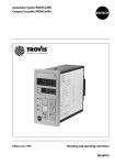
Automation System TROVIS 6400
Compact Controller
TROVIS 6493
Mounting and
Operating Instructions
EB 6493-1 EN
®
Electronics from SAMSON
Firmware version 2.03 and 3.03
Edition February 2002
Firmware versions 2.03 and 3.03
Modifications of firmware versions 2.03 and 3.03
The latest version of the TROVIS 6493 Compact Controller is equipped with an infrared interface. Apart from setting and operating the controller using the operator keys on the front panel,
the integrated infrared interface allows you to configure, parameterize and operate the controller using the TROVIS-VIEW Configuration and Operator Interface.
The software for both compact controller versions has been upgraded:
4 6493-01 Firmware version 2.03
4 6493-02 Firmware version 3.03.
The measuring range of the reference variable ( WINT, WINT) is adapted automatically to
the previously determined measuring range of the controlled variable ( IN1,
IN1 or
IN2, IN2). However, changing the measuring range of the reference variable afterwards
does not result in an automatic adaption of the measuring range of the controlled variable (see
section 3.3.1).
Automatic adaption in the CLAS function (see section 3.2.5):
The CLAS function enables you to assign the signals X and WE to the analog inputs IN1 and
IN2. By default, X is assigned to input IN2, WE is assigned to input IN1. If, however, X is assigned to input IN1, WE is automatically assigned to input IN2. So far, WE had to be assigned
manually to input IN2.
The parameter Y.PRE has been added to the PAR function.
This parameter determines the rate action of the output signal (see section 3.1).
2
EB 6493-1 EN
Contents
Contents
1
Notes . . . . . . . . . . . . . . . . . . . . . . . . . . . . . . . . . 5
2
2.1
2.2
2.3
2.4
2.5
2.6
2.7
Operation . . . . . . . . . . . . . . . . . . . . . . . . . . . . . . . 6
Display . . . . . . . . . . . . . . . . . . . . . . . . . . . . . . . . 6
Keys . . . . . . . . . . . . . . . . . . . . . . . . . . . . . . . . . . 7
Operating level. . . . . . . . . . . . . . . . . . . . . . . . . . . . . 8
Setup level . . . . . . . . . . . . . . . . . . . . . . . . . . . . . . . 9
Key number. . . . . . . . . . . . . . . . . . . . . . . . . . . . . . 10
Example for configuration and parameterization . . . . . . . . . . . . 12
TROVIS-VIEW Configuration and Operator Interface . . . . . . . . . . 16
3
3.1
3.2
3.2.1
3.2.2
3.2.3
3.2.4
3.2.5
3.2.6
3.2.7
3.2.8
3.3
3.3.1
3.3.2
3.4
3.4.1
3.4.2
3.4.3
3.4.4
3.4.5
3.4.6
3.4.7
3.4.8
3.5
3.5.1
3.5.2
3.5.3
3.5.4
Functions of the compact controller . . . . . . . . . . . . . .
PAR Control parameters . . . . . . . . . . . . . . . . . . . .
IN Input functions . . . . . . . . . . . . . . . . . . . . . . .
IN1 Input signal range IN1 . . . . . . . . . . . . . . . . . .
IN2 Input signal range IN2 . . . . . . . . . . . . . . . . . .
MEAS Measuring range monitoring for analog input 1 and 2 . .
MAN Changeover to manual mode upon transmitter failure . .
CLAS Assignment of X and WE . . . . . . . . . . . . . . . .
DI.FI Filtering of input variable X and WE . . . . . . . . . . .
SQR Root extraction . . . . . . . . . . . . . . . . . . . . . .
FUNC Function generation of X and WE . . . . . . . . . . . .
SETP Reference variable . . . . . . . . . . . . . . . . . . . .
SP.VA . . . . . . . . . . . . . . . . . . . . . . . . . . . .
SP.FU . . . . . . . . . . . . . . . . . . . . . . . . . . . .
CNTR Controller structure and functions . . . . . . . . . . . .
C.PID Dynamic behavior of controller output . . . . . . . . . .
SIGN Inversion of error Xd . . . . . . . . . . . . . . . . . .
D.PID Assignment of controller output D element . . . . . . . .
CH.CA Control mode changeover P(D)/PI(D) control . . . . . .
M.ADJ Operating point adjustment in manual mode for YPID . .
DIRE Operating direction of output variable . . . . . . . . . .
F.FOR Feedforward control . . . . . . . . . . . . . . . . . .
AC.VA Increase, decrease of actual value . . . . . . . . . . .
Output functions . . . . . . . . . . . . . . . . . . . . . . .
SAFE Initialization of constant output value Y1K1 for YPID . . .
MA.AU Manual/automatic changeover . . . . . . . . . . . .
Y.LIM Output signal limitation YPID . . . . . . . . . . . . . .
RAMP Output ramp or limitation of rate of output changes YPID .
.
.
.
.
.
.
.
.
.
.
.
.
.
.
.
.
.
.
.
.
.
.
.
.
.
.
.
.
.
.
.
.
.
.
.
.
.
.
.
.
.
.
.
.
.
.
.
.
.
.
.
.
.
.
.
.
.
.
.
.
.
.
.
.
.
.
.
.
.
.
.
.
.
.
.
.
.
.
.
.
.
.
.
.
.
.
.
.
.
.
.
.
.
.
.
.
.
.
.
.
.
.
.
.
.
.
.
.
.
.
.
.
EB 6493-1 EN
18
18
18
20
20
21
21
22
22
23
23
25
27
28
29
29
31
31
32
33
33
33
34
35
35
35
37
37
3
Contents
3.5.5
3.5.6
3.5.7
3.5.8
3.5.9
3.5.10
3.5.11
3.6
3.6.1
3.6.2
3.7
3.7.1
3.7.2
3.7.3
3.7.4
3.7.5
3.7.6
3.8
3.8.1
3.9
3.9.1
3.9.2
3.9.3
3.9.4
3.9.5
BLOC Locking of output signal YPID . . . . . . . . .
FUNC Function generation of output variable. . . . .
Y.VA Output signal range . . . . . . . . . . . . . .
Y.SRC Assignment of continuous-action output . . . .
CALC Mathematical adaption of continuous output . .
C.OUT Configuration of two-step or three-step output .
B.OUT Configuration of binary outputs BO1 and BO2
ALRM Alarm functions . . . . . . . . . . . . . . .
LIM1 Limit relay L1 . . . . . . . . . . . . . . . . .
LIM2 Limit relay L2 . . . . . . . . . . . . . . . . .
AUX Additional functions . . . . . . . . . . . . . .
RE.CO Restart conditions after power failure . . . . .
ST.IN Resetting to factory defaults . . . . . . . . . .
KEYL Operator keys . . . . . . . . . . . . . . . . .
VIEW Setting of display contrast . . . . . . . . . . .
FREQ Power frequency . . . . . . . . . . . . . . .
DP Decimal place setting . . . . . . . . . . . . . .
TUNE Start-up adaption . . . . . . . . . . . . . . .
ADAP Start-up adaption. . . . . . . . . . . . . . .
I-O View process data. . . . . . . . . . . . . . . .
CIN Firmware. . . . . . . . . . . . . . . . . . . .
S-No Serial number . . . . . . . . . . . . . . . . .
ANA View values of analog inputs. . . . . . . . . .
BIN Status of binary input and outputs . . . . . . . .
ADJ Adjusting the analog inputs and output . . . . .
.
.
.
.
.
.
.
.
.
.
.
.
.
.
.
.
.
.
.
.
.
.
.
.
.
.
.
.
.
.
.
.
.
.
.
.
.
.
.
.
.
.
.
.
.
.
.
.
.
.
.
.
.
.
.
.
.
.
.
.
.
.
.
.
.
.
.
.
.
.
.
.
.
.
.
.
.
.
.
.
.
.
.
.
.
.
.
.
.
.
.
.
.
.
.
.
.
.
.
.
.
.
.
.
.
.
.
.
.
.
.
.
.
.
.
.
.
.
.
.
.
.
.
.
.
.
.
.
.
.
.
.
.
.
.
.
.
.
.
.
.
.
.
.
.
.
.
.
.
.
.
.
.
.
.
.
.
.
.
.
.
.
.
.
.
.
.
.
.
.
.
.
.
.
.
.
.
.
.
.
.
.
.
.
.
.
.
.
.
.
.
.
.
.
.
.
.
.
.
.
.
.
.
.
.
.
.
.
.
.
.
.
.
.
.
.
.
.
.
.
.
.
.
.
.
39
39
39
40
40
41
50
51
52
52
53
53
54
54
54
55
55
55
55
58
58
58
58
59
59
4
4.1
4.2
4.3
Practical examples . . . . . . . . . . .
Fixed set point control . . . . . . . . .
Follow-up control . . . . . . . . . . . .
Follow-up control with function generation
.
.
.
.
.
.
.
.
.
.
.
.
.
.
.
.
.
.
.
.
.
.
.
.
.
.
.
.
.
.
.
.
.
.
.
.
.
.
.
.
.
.
.
.
.
.
.
.
.
.
.
.
.
.
.
.
.
.
.
.
61
61
62
64
5
5.1
5.2
5.3
5.4
Start-up. . .
P controller .
PI controller .
PD controller
PID controller
.
.
.
.
.
.
.
.
.
.
.
.
.
.
.
.
.
.
.
.
.
.
.
.
.
.
.
.
.
.
.
.
.
.
.
.
.
.
.
.
.
.
.
.
.
.
.
.
.
.
.
.
.
.
.
.
.
.
.
.
.
.
.
.
.
.
.
.
.
.
.
.
.
.
.
67
67
67
68
68
.
.
.
.
.
.
.
.
.
.
.
.
.
.
.
.
.
.
.
.
.
.
.
.
.
.
.
.
.
.
.
.
.
.
.
.
.
.
.
.
.
.
.
.
.
.
.
.
.
.
.
.
.
.
.
.
.
.
.
.
.
.
.
.
.
.
.
.
.
.
6
Installation . . . . . . . . . . . . . . . . . . . . . . . . . . . . . . 70
7
Electrical connections . . . . . . . . . . . . . . . . . . . . . . . . . 72
8
Technical data . . . . . . . . . . . . . . . . . . . . . . . . . . . . 74
Index . . . . . . . . . . . . . . . . . . . . . . . . . . . . . . . . 101
4
EB 6493-1 EN
Notes
1
Notes
The TROVIS 6493 Compact Controller is a microprocessor-based controller with a flexible software design for the automation of industrial process plants. It is suitable for single control loops
as well as for more complex control tasks. The flexible software design allows you to configure
control circuits without changing the hardware. The read-only functions can be adapted to your
specific plant configuration.
These Mounting and Operating Instructions (EB) describe the powerful features of the compact
controller. First, we will explain how to operate the controller conveniently. All functions and
parameters are described in section 3. Section 4 provides some practical examples to show you
which settings need to be adjusted for the specific cases of application. In sections 6 and 7, the
electrical connections and the installation are dealt with. The index at the end of this EB gives
you quick and direct reference in case you have specific questions or problems.
4 The controller may only be installed, started up or operated by trained and ex-
perienced personnel familiar with the product.
According to these mounting and operating instructions, trained personnel refers to individuals who are able to judge the work they are assigned to and recognize possible dangers due to their specialized training, their knowledge
and experience as well as their knowledge of the applicable standards.
4 The controller has been designed for use in electrical power systems. For wi-
ring and maintenance, you are required to observe the relevant safety regulations.
4 Proper shipping and appropriate storage are assumed.
EB 6493-1 EN
5
Operation
2
Operation
The TROVIS 6493 Compact Controller can be operated either directly using the keys on the
front panel or using the TROVIS-VIEW Configuration and Operator Interface (see section 2.7)
for configuration, parameterization and operation.
In the following, we will explain how to operate the controller with the keys on the front panel.
First, open the folded back cover of this EB. There is the controller's front panel with its display
and six keys. Principally, there are two levels which provide different key functions and different
displays: the operating level and the setup level. You may define the functions of the compact
controller via configuration and parameterization. A table listing all details required for
parameterization and configuration is provided in Appendix A. In addition, we will explain
how to configure and parameterize using this table in section 2.6.
2.1
Display
Depending on the selected level, the display shows the following variables and operating states
(see folded back cover):
No.
Operating level
Setup level
1
Controlled variable X
2
Value assumed by W, W2,
WE, Y or Xd
Designations, settings and values of
functions, parameters; abbreviations
are listed in Appendix A
3
Limit relay L2 active
Not displayed
4
Three-step output –
Not displayed
5
Limit relay L1 active
Not displayed
6
Three-step output + or two-step output
Not displayed
7
Alarm messages (see section 3.2.3)
Not displayed
8
Hand icon displayed in manual mode
Not displayed
No icon in automatic mode
9
and
are used for minimum and
Press the
key to display W, W2,
maximum
values
of different parameWE, Y or Xd% in sequence. The assoters.
ciated value appears in (2).
W2 and WE only when they have been
activated (see section 3.3.1).
10
6
Bar graph display of Xd in percent
EB 6493-1 EN
Not displayed
Operation
2.2
Keys
The compact controller is operated using six keys whose function depends on the selected level.
Key
Function in operating level
Function in setup level
Enter key
(yellow)
Provides access to setup level.
Activates a new reference variable if
its icon (W, W2 or WE) blinks in the
display (9).
Activates functions and parameters
to be changed (display blinks).
Selector key
Confirms new settings of functions
or parameters (display stops blinking).
Switches lower display section be- Provides access to parameter level.
tween:
W
internal reference variable 1, Jump within the value range in paW2* internal reference variable 2, rameter level.
WE* external reference variable,
Y
continuous output variable,
Xd% error
* Only when selected, see p. 27.
Manual/automatic key
Changes from manual to automatic No function
mode and vice versa.
In manual mode,
Cursor keys
Return key
appears.
Change the value of W or W2 when
they are displayed in the lower display section.
Change controller output in manual
mode, and when Y is indicated in
the lower display section.
Browse within the main groups,
functions, settings and parameters.
Change function settings and parameter values.
Displays the current reference vari- Return to preceding level up to operable.
ating level.
No key pressed After approx. 5 minutes, display Changes to operating level after
changes to current reference vari- approx. 5 minutes.
able.
Exception: in manual mode and when output
variable is displayed
EB 6493-1 EN
7
Operation
2.3
Operating level
In the operating level, Press
you can
Comments
view different variables:
W, W2, WE, Y, Xd
Press selector key repeatedly until the desired variable appears on the display.
W2 and WE are only displayed when you have
activated them in SETP
(see section 3.3.1).
select another reference
variable
Press selector key repeatedly until the desired reference variable (W, W2
or WE) is displayed.
When the reference variables are deactivated, W,
W2 or WE blink.
Whereas they do not
blink when active.
Press the enter key.
change the value of the
internal reference variable W or W2
Press selector key repeat- New value is accepted at
edly until W or W2 ap- once.
pears.
No confirmation required.
Change the value using
the cursor keys.
switch to manual mode
Press manual/automatic In manual mode, use the
key.
cursor keys to determine
the output variable.
change the output variable
Press manual/automatic
key to display Y.
Change its value using
the cursor keys.
enter setup level for
configuration and
parameterization
8
EB 6493-1 EN
Press enter key.
Do not press the enter key
when W, W2 or WE
blink, otherwise you activate a new reference variable!
Operation
2.4
Setup level
This level enables you to configure and parameterize the compact controller. You can enter the
setup level from the operating level by pressing the enter key once. Here, you may adapt preset
functions to your specific needs (configure) and change parameters. The functions are arranged in nine main groups:
4
4
4
4
4
4
4
4
4
PAR
NI
SETP
CNTR
OUT
ALRM
AUX
TUNE
I-O
(control parameters)
(input functions)
(reference variable)
(control structure and functions)
(output functions)
(alarm functions)
(additional functions)
(start-up adaption)
(view process data)
The parameters are always connected to the function they are assigned to.
This means that pressing
allows you to access only the parameters that are relevant for the
particular function you have chosen.
Appendix A lists all functions and parameters provided by the compact controller. The table includes the main groups and their functions with the setting options in the left column, and the associated parameters in the right column. This table will considerably facilitate learning how to
operate the controller. You only have to keep the following in mind:
To move from left to right (in columns), press
.
To move in the reverse direction (from right to left), use the return key
.
The key number (KEY) must be entered in setup level only when a function or parameter is
changed for the first time.
The right column of the table, i.e. the parameters, can be accessed by pressing the selector key
. Again, press the enter key to move forward in columns.
To move in rows from top to bottom, press
To move in reverse direction, press
.
. Confirm new settings or the new value by pressing
.
An example in section 2.6 illustrates how to configure and parameterize the controller properly.
Note!
The display changes from setup level to operating level after 5 minutes when no key is pressed!
EB 6493-1 EN
9
Operation
2.5
Key number
You are prompted to enter the key number when you want to change the settings of
functions and parameters.
The compact controller can be operated with or without a key number. Factory default is without
key number. Each time you wish to change a function or parameter in the setup level for the first
time, you will be prompted to enter the key number. Proceed as follows:
Press
Reading on display
Comment
KEY blinks. Enter the key number.
Skip the next step for operation without
key number.
Note! If the reading on the display looks
like this, the key number can always be
changed (see next section).
KEY blinks.
Enter the valid key number. In this example it is 12.
or
If you have entered the correct key number, the selected function blinks in the
display. If not, you are prompted to enter the key number again with 1 appearing in the upper display section. This means that the controller operates
with key number.
Enter the key number again or cancel by pressing the return key
.
Changing the key number
You may define a new key number or set up the controller to operate without key number.
When defining a new key number, you need to know the service key number which is to be
found on page 104. To prevent misuse, you should cut it out or make it unreadable.
Proceed as follows to define a new key number:
10
EB 6493-1 EN
Operation
Press
Reading on display
Comment
You are in operating level.
The reading on the display looks like this.
3x
KEY blinks.
Note! If the reading on the display looks
like this, the key number can always be
changed.
KEY blinks.
or
Enter the service key number. See page
104.
You have confirmed the service key number.
You now see KEYP which stands for key
number programming. The upper display section shows the current key number. The four dashes stand for "without
key number".
Enter the new key number (---- for "without key number"). We have chosen 12 in
this example.
EB 6493-1 EN
11
Operation
Press
Reading on display
Comment
You have confirmed the new key number
and returned to the selected function or
parameter. In our example, we have returned to the Kp value.
2.6
Example for configuration and parameterization
We will use the "Table of functions and parameters" provided in Appendix A for this example.
The exercise consists of setting up the controller as a PID controller and adjusting the parameters
accordingly.
The biggest problem is of course where to find the appropriate function and what to change in
this function. There are two ways to proceed. You may search for the function in the table in Appendix A, which also provides reference to further details. Or you may refer to the index. For
the PID controller, you will find the C.PID function which belongs to the main group CNTR. As
you already know which main group is to be activated and which function is to changed, proceed as follows:
Press
Reading on display
Comment
You are in operating level.
The display reading will be similar to the
one depicted here.
You have entered the setup level. The display shows the first main group PAR.
Main groups are always displayed in a single line. You are now in the first column of
the table in Appendix A.
Note! If you press the enter key again, you
get to Kp (see page 14).
12
EB 6493-1 EN
Operation
Press
repeatedly
until CNTR
appears on the
display.
Reading on display
Comment
Browse through the main groups (in the table in Appendix A, you move from top to
bottom) until you get to the main group
CNTR. Here, you can adjust the dynamic
behavior of the controller output.
You have entered the main group CNTR
(moved to the right in table). You have
reached the functions. Functions are always
marked by -CO- for configuration.
The display shows the first function C.PID,
"Dynamic behavior of controller output". In
our case, the function we were looking for.
You have moved one column further to the
right. You now see the current settings of the
PI action function. These settings are to be
changed to PID action.
KEY blinks
You are prompted to enter the key number
(KEY). This prompt is displayed when you
change a function for the first time after entering the setup level. You will not be
prompted for subsequent changes.
If you do not use a key number, skip the next
step.
Use the cursor keys to enter the key number.
or
In our example it is 27.
EB 6493-1 EN
13
Operation
Press
Reading on display
Comment
The display will look like this if you have entered the key number correctly. If not, you
will be prompted again. The upper line
blinks, meaning that you may change the
settings of the function. In the table, you
have moved one column further to the right
and have reached "Setting options".
The upper line blinks.
Use the cursor keys to select the desired setting. In our example it is Pld for PID action of
the controller output.
or
Confirm changes with the enter key. The upper line stops blinking. The first part of the
task is completed.
Now the control parameters KP, TN and TV
are to be changed. To do so, enter the parameter level.
Press the selector key to open the parameter
level. In the table, you have jumped to the
first column on the right page.
C.PID and CP.YP are displayed alternately
in the lower display line.
The first parameter Kp is displayed.
Note! You can go directly from the PAR display to this display by pressing the yellow
enter key once. You may only change the
control parameters KP, TN, TV and Y.PRE.
14
EB 6493-1 EN
Operation
Press
Reading on display
Comment
KP blinks, i.e. you can change this parameter.
or
Enter a new value for KP. In our example it
is 1.5. The upper line continues to blink.
You have confirmed the new value for KP.
The upper line stops blinking.
The next parameter is displayed.
To change this and other parameters, proceed as described for KP, i.e. repeat the
steps in the fields highlighted in gray.
repeatedly
until the display
looks like this!
You are back in the operating level.
indicates that the compact controller is in
manual mode.
EB 6493-1 EN
15
Operation
2.7
TROVIS-VIEW Configuration and Operator Interface
The TROVIS 6493 Compact Controller can be configured, parameterized and operated using
SAMSON's TROVIS-VIEW Configuration and Operator Interface via the infrared interface integrated in the front panel.
Operating TROVIS-VIEW is similar to working in Windows Explorer. Apart from configuration,
parameterization and operation, TROVIS-VIEW provides additional features to record the
compact controller. These are, for example, editing plant texts, saving and printing various configuration and parameterization data, tabulating analog inputs and outputs as well as binary
status reports.
The TROVIS-VIEW software with the device-specific module for the TROVIS 6493 Compact
Controller is delivered on a CD-ROM (order no. 6661-1031).
For system requirements, refer to the TROVIS-VIEW Data Sheet T 6661 EN or to the readme.txt
file in the root directory of the CD-ROM.
Communication between the PC and the compact controller is established via the infrared interface integrated in the controller. The IR interface can be accessed via the controller's front
panel. It is located to the left of the yellow enter key (see Fig. 1).
An infrared adapter (order no. 8864-0900) is required to transfer data between the PC's serial
RS-232 interface and the controller's integrated infrared interface.
Note!
For additional information on installation, connection and operation, refer to the Mounting
and Operating Instructions EB 6493-2 EN.
16
EB 6493-1 EN
Operation
TROVIS 6493
Xd%
W
0.7 m
L1
2
1
L2
25°
1
Infrared adapter
2
Optional
COM 1...COM 4 port of
computer
Fig. 1 · Connecting an infrared adapter
EB 6493-1 EN
17
Functions of the compact controller
3
Functions of the compact controller
In this section, all functions of the setup level are described. We assume that you are familiar
with the operation of this controller and know how to change functions and parameters.
The compact controller contains nine main groups: PAR, IN, SETP, CNTR, OUT, ALRM, AUX,
TUNE and I-O. Each of the sections 3.1 to 3.9 is dedicated to one of the main groups. The main
groups have different functions which can be identified by -CO- displayed in the upper display
section. The functions are explained in the subsections (e.g. 3.2.1); the subsection titles already
indicate the functions' designation. Almost every function provides different setting options from
which you can choose one to adapt this function to your specific needs. The setting options of
the functions are marked with a small grey square
in these instructions. If you need to adjust
parameters for your function, they will be specified and explained, if necessary. The value
range of the parameters and factory defaults can be found in Appendix A.
3.1
PAR Control parameters
This main group serves a special purpose. In contrast to all other main groups, it does not include any functions. When you open this level, the controller immediately jumps to the parameter level where the control parameters Kp, Tn, Tv and Y.PRE can be set.
This main group allows you to quickly set the control parameters. You may also adjust the same
settings in the main group CNTR, with the C.PID function.
3.2
IN Input functions
This main group defines all the functions of the two analog inputs In1 and In2. You may specify
the input signal range and assign the analog inputs to the controlled variable X or the external
reference variable WE. In addition, you can determine the measuring range of both signals.
You may also perform measuring range monitoring. Moreover, the input signal can be filtered
or functions may be generated from it.
18
EB 6493-1 EN
D
D
MEAS
MAN
Measuring range
monitoring
IN2
A
IN1
A
IN
IN2
IN1
I–O
CLAS[X]
CLAS[WE]
X
WE
Input
assignment
DI.FI[X]
F
DI.FI[WE]
F
Dig. filter
IN
SQR[X]
X
SQR[WE]
WE
Root
extraction
CO.VA
WE.VA
FUNC[X]
FUNC[WE]
Function generation
N
I–O
I
LIM2
LIM2[L2.X]
LIM1[L1.X]
LIM2[L2.WE]
LIM2
LIM1
LIM1[L1.WE]
LIM1
ALRM
Functions of the compact controller
Fig. 2 · Main group IN
EB 6493-1 EN
19
Functions of the compact controller
3.2.1 IN1 Input signal range IN1
This function enables you to define the input signal type and range for the analog input In1. The
parameters' lower and upper range values must be given as absolute values.
Choose between:
g
g
g
g
0-20 mA
4-20 mA
0-10 V
2-10 V
0 to 20 mA input
4 to 20 mA input
0 to 10 V input
2 to 10 V input
Parameters to be set
IN1
Lower range value as absolute value
IN1
Upper range value as absolute value
3.2.2 IN2 Input signal range IN2
Note that there are two hardware versions for the analog input In2: controller version 6493-01
(model no. on the name plate) has a temperature sensor or potentiometer input, whereas controller version 6493-02 has a mA input.
This function enables you to define the input signal type and range for the analog input In2. The
measuring range must be specified with the parameters IN2 and IN2. Make sure that the
span is not smaller than 100 °C.
Choose between:
g
g
g
g
g
100 PT
1000 PT
100 NI
1000 NI
0-1 KOHM
Pt 100 resistance thermometer, hardware range
Pt 1000 resistance thermometer, hardware range
Ni 100 resistance thermometer, hardware range
Ni 1000 resistance thermometer, hardware range
0 to 1000 Ω input
–100 to 500 °C
–100 to 500 °C
–100 to 500 °C
–60 to 250 °C
Parameters to be set
IN1
Lower range value as absolute value
IN1
Upper range value as absolute value
This function enables you to define the input signal type and range for the analog input In2. Enter the lower and upper range values as absolute values of the parameters you require.
Choose between:
g 0-20 mA 0 to 20 mA input
g 4-20 mA 4 to 20 mA input
20
EB 6493-1 EN
Functions of the compact controller
Parameters to be set
IN2
Lower range value as absolute value
IN2
Upper range value as absolute value
3.2.3 MEAS Measuring range monitoring for analog input 1 and 2
This function enables you to define whether the measuring ranges of the analog inputs are to be
monitored either for exceeding or falling below the measuring range.
Choose between :
g
g
g
g
oFF ME.MO
In1 ME.MO
In2 ME.MO
ALL ME.MO
No measuring range monitoring
Measuring range monitoring of analog input IN1
Measuring range monitoring of analog input IN
Measuring range monitoring of both analog inputs IN1 and IN2
When values exceed or fall below the measuring range, this is signalized on the display by the
alarm message icon . The binary output is set for alarm messages. In addition, "__o1" blinks
in the upper display section when values exceed the measuring range, "__u1" blinks when values fall below the measuring range of analog input 1, or of the analog inputs 1 and 2. When
analog input 2 exceeds or falls below the measuring range, " __o2" or "__u2" appears on the
display. Whenever values exceed or fall below the measuring range, the compact controller
can change to manual mode (see section 3.2.4).
3.2.4 MAN Changeover to manual mode upon transmitter failure
This function enables you to define whether the controller switches to manual mode, and which
output value is generated when the measuring range is exceeded or not reached. This function
only becomes effective when measuring range monitoring has previously been activated in the
MEAS function (see previous section 3.2.3). Manual mode is easily recognizable by
on the
display.
Choose between:
g oFF FAIL No changeover to manual mode upon transmitter failure
g F01 FAIL Changeover to manual mode with constant output value Y1K1
g F02 FAIL Changeover to manual mode with last output value received
Parameter to be set
Y1K1 Constant output value
EB 6493-1 EN
21
Functions of the compact controller
Note!
When values exceed or fall below the measuring range, Y1K1 only becomes effective when
the compact controller is in automatic mode.
The parameter Y1K1 can also be set in the main group OUT via the SAFE function as well as in
the main group AUX via the RE.CO function (see sections 3.5.1 and 3.7.1).
3.2.5 CLAS Assignment of X and WE
Internally, the compact controller operates with the analog input signals X and WE. The CLAS
function is used to assign these signals to the analog inputs IN1 or IN2. By default, X is assigned
to analog input IN2 and WE to analog input IN1.
Assignment of X
g IN1 X
g IN2 X
X assigned to analog input IN1
X assigned to analog input IN2
Assignment of WE
g IN1 WE
g IN2 WE
WE assigned to analog input IN1
WE assigned to analog input IN2
3.2.6 DI.FI Filtering of input variable X and WE
This function enables you to determine whether X and/or WE are to be filtered.
The first-order filter (low-pass filter or Pt1 behavior) smooths the selected signals and suppresses
input signal interferences of higher frequency.
The time constant of the Pt1 element is defined by the parameter TS.X for the input signal X, and
by TS.WE for the input signal WE. The time constant is given in seconds.
Filtering of input variable X
g oFF X
g on X
Filtering of input variable X deactivated
Filtering of input variable X activated
Filtering of input variable WE
g oFF WE
g on WE
22
EB 6493-1 EN
Filtering of input variable WE deactivated
Filtering of input variable WE activated
Functions of the compact controller
Parameters to be set
TS.X
Time constant X filter in seconds
TS.WE Time constant WE filter in seconds
3.2.7 SQR Root extraction
This function enables you to root-extract the signals X as well as WE. Thus, you may easily calculate the flow rate from a differential pressure, for example. Choose between:
Root extraction X
g oFF X
g on X
No root extraction of signal X
Root extraction of X
Root extraction WE
g oFF WE
g on WE
No root extraction of signal WE
Root extraction of WE
3.2.8 FUNC Function generation of X and WE
You may apply function generation to the signal X as well as to WE. Choose between:
Function generation of X
g oFF X
g on X
No function generation of signal X
Function generation of X
Function generation of WE
g oFF WE
g on WE
No function generation of signal WE
Function generation of WE
EB 6493-1 EN
23
Functions of the compact controller
Function generation means
that a signal is re-evaluated to
be further processed. This allows you to adapt auxiliary,
MAX
reference or equivalent variK7.Y
ables required for measuring
E'
E
K5.Y
and control to your specific
control loop. For this purpose,
you must specify 7 points to
characterize the relationship
K1.Y
between signal E to be funcMIN
tion-generated (X or WE) and
K5.X K6.X K7.X
K1.X
E
the desired new output signal
MBA
MBE
E' (X' or WE'). This relationMBE Upper range value
ship should be known to you
MBA Lower range value
either from physical laws, experience or from calculated
Fig. 3 · Example of parameter for function generation
values (e.g. the relationship
between steam pressure and temperature). We recommend that you either draw up a table or
create a curve in a Cartesian coordinate system. Choose the 7 points in such a way that a curve
can easily be created by drawing straight lines between two adjacent points.
E'
The points are entered via the parameters K1.X to K7.X for the input signal, and K1.Y to K7.Y
for the output signal. The values are entered as absolute values, i.e. in units of measurement
comprehensible to the user (e.g. in °C, bar or %).
Even when the signal curve can be sufficiently characterized by less points, 7 points must be
specified. If applicable, they can be defined in the same position as the last point.
The parameters MIN and MAX are used to determine the measuring range of the output signal
E'. It corresponds to that of signal E (not function-generated) with reference to the output signal
E'. By entering these two parameters, a proper basis for the percentage calculation performed
by the software is created.
If K1.Y or K7.Y do not agree with MIN and MAX, the output values for the function-generated
signal, which are below or above these limits, are constantly set to K1. Y or K7.Y. In doing so,
the compact controller completes the polygonal curve by generating straight lines (see Fig. 3).
If you have entered an output value greater than MAX or smaller than MIN, it will be set to the
value of MAX or MIN.
You will find an application example for function generation in section 4.3.
24
EB 6493-1 EN
Functions of the compact controller
Note!
The course of the polygonal curve is not limited by the software. Polygonal curves with more
than one maximum or minimum are possible. However, make sure that you assign only one
ordinate value to one abscissa value. Otherwise, you risk to lose clear assignment of the input signal.
Parameters to be set
N
MI
MAX
K1.X to K7.X
K1.Y to K7.Y
3.3
Lower range value of output signal
Upper range value of output signal
Input values for points 1 to 7
Output values for points 1 to 7
SETP Reference variable
This main group enables you to determine one or more reference variables, and you can switch
between them as required. The compact controller has two internal reference variables W and
W2 for fixed set point control. However, you must activate W2 to use it. The default setting of
the controller is fixed set point control. To obtain follow-up control, you only need to activate the
external reference variable WE. However, the input WE can also be used for fixed set point
control, serving as an input for the position transmission of a three-step output with external position feedback, or as feedforward control. If you want to activate one of these control modes,
you need to adjust them in this main group. Moreover, you may select a set point ramp with various starting conditions.
EB 6493-1 EN
25
I–O
FE.CO
Fig. 4 · Main group SETP
26
EB 6493-1 EN
W/W2/WE
SP.VA
CH.SP
SP.FU
W2
BI
W
W2
WE
W
WE
Reference variable selection
SETP
SP.FU
RAMP
Set point
ramp
SP.CO
I–O
Functions of the compact controller
Functions of the compact controller
3.3.1 SP.VA
This function enables you to define which reference variables are active: W, W2 and/or WE.
When you activate WE, follow-up control will automatically be effective, unless you use WE as
input for the position transmission of a three-step output with external position feedback (F01
WE), or for feedforward control (F02 WE).
Parameter level allows you to define the desired value of the reference variable (W, W2) and its
measuring range ( WINT,
WINT). This range must be identical to the measuring range of
the controlled variable ( IN1, IN1 or IN2, IN2). You may limit this measuring range
with the parameters WRAN and
WRAN. The value of the reference variable can only be
chosen between
WRAN and
WRAN. This also applies in operating level.
Choose between:
Internal reference variable W
g on W
Internal reference variable W, always active
Parameters to be set
W
Internal reference variable W
Lower range value for W, W2, WE
Upper range value for W, W2, WE
Limitation of W, W2, WE, lower limit
Limitation of W, W2, WE, upper limit
WINT
WINT
WRA
N
WRA
N
Internal reference variable W2
g oFF W2
g on W2
Internal reference variable W2 not active
Internal reference variable W2 active
Parameter to be set
W2
Internal reference variable W2
External reference variable WE
g
g
g
g
oFF WE
on WE
F01 WE
F02 WE
External reference variable not active
External reference variable active
WE as input for external position feedback with three-step output
WE as input for feedforward control (in this case, WE is not displayed
in operating level! It is only displayed in I-O level; see section 3.9.3).
EB 6493-1 EN
27
Functions of the compact controller
3.3.2 SP.FU
This function enables you to define a set point ramp and change between the different reference
variables via the binary input.
W
WINT
W2
W1
WINT
TSRW
t1
TSRW
t
Upper range value
Lower range value
W1
W2
Old value of ref. variable
Transit time of set
point ramp
t1
Actual transit time of set
point ramp
New value of ref. variable
Set point ramp means that the
reference variable changes at
a constant rate. When the reference variable is changed,
the compact controller follows
this change with a certain delay to prevent oscillations. The
transit time of the set point
ramp is determined by the parameter TSRW. TSRW refers
to the entire defined measuring range, e.g.
WINT and
WINT. When the reference
variable changes from a value
W1 to a new value W2, the
actual transit time of the set
point ramp is the time t1, as illustrated in Fig. 5.
You may start the set point
ramp via the binary input, and
choose between two starting values (actual value or parameter WIRA). The set point ramp can
also be active upon each change of the reference variable.
Fig. 5 · Set point ramp
TSRW = t1 x |
WINT –
WINT|
| W2 – W1|
Choose between:
Set point ramp
g
g
g
g
oFF RAMP
F01 RAMP
F02 RAMP
F03 RAMP
Set point ramp deactivated
Set point ramp starts with BI1 and actual value
Set point ramp starts with BI1 and WIRA
Set point ramp activated, no starting conditions
Parameters to be set
TSRW
WIRA
28
Transit time of set point ramp in seconds
Starting value of reference variable as absolute value
EB 6493-1 EN
Functions of the compact controller
You can use the binary input to change between the internal and external reference variable:
Changeover of W via BI1
g oFF CH.SP
g F01 CH.SP
g F02 CH.SP
No changeover between internal reference variable W (W2) and
external reference variable WE
Changeover between active internal reference variable W (W2)
and external reference variable WE via binary input BI1
Changeover between internal reference variables W and W2 via
binary input BI1. If W2 is active when setting the binary input, no
function will be performed. The function -CO- SP.VA may not be set
to "ON" for WE.
Note!
Several functions may be assigned to the binary input!
3.4
CNTR Controller structure and functions
This main group enables you to determine the functions for the control algorithm. You may define the dynamic behavior of the controller output, the operating direction of the error and the
output variable. In addition, you may select the input variable for the D element and set a control mode changeover. If you use the input WE for feedforward control, you may link this signal
to parameters. Optionally, the binary input can be used to influence the actual value. Finally,
you may define an operating point in manual mode, which is then added to the calculated operating point in automatic mode.
3.4.1 C.PID Dynamic behavior of controller output
This function enables you to define a dynamic behavior for the compact controller according to
the control algorithm. Factory default is PI action. You can also set the control parameters.
Moreover, you may define the dead band DZXD for the error; the control signal does not
change within this band. In addition, you can determine limits for the error using the parameters
DZXD and
DZXD. These minimum or maximum values of error are used for output
signal calculation.
Choose between:
g
g
g
g
g
P
PI
PD
PID
PPI
P controller
PI controller
PD controller
PID controller
P2I controller
EB 6493-1 EN
29
WE
—
Fig. 6 · Main group CNTR
30
EB 6493-1 EN
—
* Reading in the
operating level
F.FOR
(+/–) ( WE – FC.K1 ) x FC.K2 + FC.K3
>0
Feedforward control
CNTR
+
AC.VA
AV.K1
BI
+
X
XD
Actual
value*
X
W
–
+
SIGN
*–1
Comparator
XD
X
DPID
C.PID
Dead
band
I
P
M.ADJ
CH.CA
D
Limiter
+
L1.XD
LIM1
Y.PRE
+
DIRE
Reversal of
operating
direction
L2.XD
LIM2
Limit monitor
ALRM
Xd%
Functions of the compact controller
Functions of the compact controller
Parameters to be set
KP
NT
TV
TVK1
Y.PRE
DZXD
DZXD
DZXD
Proportional-action coefficient
Reset time
Derivative-action time
Derivative-action gain
Y rate action
Dead band of error
Limitation of error, lower limit
Limitation of error, upper limit
3.4.2 SIGN Inversion of error Xd
This function enables you to reverse the input operating direction. Multiplication by –1 converts
an increasing error into a decreasing one, or vice versa, a decreasing error into an increasing
one. This also inverts the operating direction of the output signal. Note the set operating direction in the DIRE function (see section 3.4.6)! There, the operating direction of the output signals
may be changed as well.
Choose between:
g dir.d
g in.d
No inversion of error
Inversion of error
3.4.3 D.PID Assignment of controller output D element
When dynamic behavior with D component has been selected (see section 3.4.1), you may set
different input variables for the D element: error or controlled variable.
If you have selected error, the compact controller reacts to a fast change in the controlled variable, the reference variable or the disturbance variable by generating a D-step response.
If you select the controlled variable, only a fast change in the controlled variable causes a
D-step response in the output variable. The D component of the compact controller does not
consider changes in the disturbance or the reference variable.
Choose between:
g F01 DP.YP
g F02 DP.YP
Assignment of controller output D element to error
Assignment of controller output D element to controlled variable
EB 6493-1 EN
31
Functions of the compact controller
3.4.4 CH.CA Control mode changeover P(D)/PI(D) control
Control mode changeover enables the compact controller to be operated under varying operating conditions with different
dynamic behaviors according
W, XD
to the control algorithm. Generally, control mode changeP(D)
CLI.P
over is only useful when a control action with I component
has been selected (see section
PI(D)
3.4.1).
CLI.M
P(D)
t
The control mode changeover
function activates either P (or
PD) or PI (or PID) control depending on the error or reference variable.
Fig. 7 · Control mode changeover
Beyond the definable range of
the reference variable or error, the parameters for P or PD control are used to operate the controller. Within this definable
range, the I component is included. The range is defined by the parameters CLI.P and CLI.M, as
illustrated in Fig. 7.
Special feature of F01 CC.P setting:
If the controller changes from manual to automatic mode while the error is outside the defined
range, the operating point is determined by the last manual output value. The operating point
applies until the error returns to the range. The operating point of PI(D) action is determined
there. If the error moves outside the range again, the last output value is set as the operating
point. If the controller changes from automatic to manual mode, the operating point required
for the plant must be reset again before returning to the automatic mode. The operating point is
only saved temporarily (Y.PRE parameter does not have any effect). After power failure, the operating point must be reset in manual mode.
Choose between:
g oFF CC.P
g F01 CC.P
g F02 CC.P
No control mode changeover
Control mode changeover activated by error
Control mode changeover activated by reference variable
Parameters to be set
CLI.P
CLI.M
32
Maximum limit for range of PI(D) control
Minimum limit for range of PI(D) control
EB 6493-1 EN
Functions of the compact controller
3.4.5 M.ADJ Operating point adjustment in manual mode for YPID
This function enables you to activate operating point adjustment in manual mode. In the factory
defaults, this option is deactivated. To activate the operating point adjustment proceed as follows: in manual mode, adjust the output variable using the cursor keys to the desired value.
When switching to automatic mode, the last value received is stored as operating point and
added to the output variable calculated by the P or PD algorithm. The stored operating point remains effective until the operating point adjustment in manual mode is deactivated by selecting
oFF MA.YP, or until a new operating point is adjusted in manual mode.
If you deactivate operating point adjustment in manual mode, the output variable specified in
manual mode will assume the calculated value within approx. two seconds.
Choose between:
g oFF MA.YP
g on MA.YP
Operating point adjustment in manual mode for YPID deactivated
Operating point adjustment in manual mode for YPID activated
3.4.6 DIRE Operating direction of output variable
The output variable may either act directly or inversely to the error. This operating direction is
defined with the DIRE function. Note that the operating direction can also be inverted with the
SIGN function (see section 3.4.2).
Choose between:
g dir.d DI.AC
Direct operating direction of output variable (factory default)
g in.d DI.AC
Inverted operating direction of output variable
3.4.7 F.FOR Feedforward control
You may use the input WE for feedforward control (see section 3.3.1). The disturbance signal
can be multiplied and additively linked by parameters according to the formula:
± (WE – FC.K1) FC.K2 + FC.K3. The following then applies: (WE – FC.K1) ≥ 0.
The signal is then connected to the controlled variable. FC.K1, FC.K2 and FC.K3 are constants
you have to define in parameter level. The mathematical sign of the formula stated above is determined in the F.FOR function.
Choose between:
g oFF FECO
Feedforward control deactivated (factory default)
g POS FECO
Feedforward control with positive sign
g nE6 FECO
Feedforward control with negative sign
Parameters to be set
FC.K1
FC.K2
FC.K3
Constant for formula stated above
Constant for formula stated above
Constant for formula stated above
EB 6493-1 EN
33
Functions of the compact controller
a)
WE' [%]
WE’ = + (WE – FC.K1) FC.K2 + FC.K3
FC.K2
FC.K3
FC.K1
b)
WE' [%]
WE [%]
WE’ = – (WE – FC.K1) FC.K2 + FC.K3
FC.K3
FC.K2
FC.K1
WE [%]
-WE' [%]
Fig. 9 · Feedforward control with positive (a) and negative (b) signs
3.4.8 AC.VA Increase, decrease of actual value
This function enables you to increase or decrease the actual value.
Upon activation of the binary input, the input signal X is additively linked to the parameter
AV.K1. The new actual value is now used for control. It is also indicated in the upper display
section for the controlled variable. Upon deactivation of the binary input, the input signal X is
used for control again. In parameter level, the parameter AV.K1 is given in percent ranging
from –110 to 110 %. When entering, for example, AV.K1 = 30 %, the current value for X will be
increased from 50 to 80 %.
Choose between:
g oFF IN.DE
g bi1 IN.DE
Parameter to be set
AV.K1 Constant in %
34
EB 6493-1 EN
Increase, decrease of actual value deactivated
Increase, decrease of actual value via binary input BI1
Functions of the compact controller
Note! Several functions can be assigned to the binary input!
3.5
Output functions
This main group enables you to define the output functions of the compact controller. You may
specify whether the compact controller operates with continuous-action or switching output. The
output signal can be limited and ramps can be defined. You can also output X, WE or XD to the
continuous output and transfer them to a recorder. In addition, mathematical adaptations can
be made for the continuous-action output. The switching outputs can be used as binary outputs
to signalize varying operating conditions. The following functions can be assigned to the binary
input in this main group: locking of the output signal, manual/automatic changeover, starting
an output ramp or initializing the second output variable Y1K1.
3.5.1 SAFE Initialization of constant output value Y1K1 for YPID
This function enables you to give out a predefined value for the output variable at the controller
output if the binary input has been activated. This output value is the parameter Y1K1. It is adjusted in percent in parameter level.
g oFF SA.VA
g bi1 SA.VA
Deactivated
Initializing Y1K1 via binary input BI1
Parameter to be set
Y1K1
Constant output value in %
Note! Several functions can be assigned to the binary input!
3.5.2 MA.AU Manual/automatic changeover
When choosing the bi1settings in this function, the controller switches to manual mode upon activation of the binary input and locks the manual/automatic key. When the binary input is deactivated, the controller switches back to automatic mode. Exception: if the controller was in manual mode upon activation of the binary input already, it remains in manual mode. Manual
mode is indicated by the
on the display.
Choose between:
g oFF CH.MA
g bi1 CH.MA
Function deactivated
Transfer to manual mode via binary input BI1
Note! Several functions can be assigned to the binary input!
EB 6493-1 EN
35
36
EB 6493-1 EN
Fig. 9 · Main group OUT
YPID
X
XD
WE
Y.LIM
C.OUT
2stp
3stp int. RF 1/– PPC
3stp ext. RF
Y*
Y.SRC
3)
2)
Assignment to limit relay L1, L2
Assignment to binary output BO1, BO2
Assignment to two-step/three-step output
OUT
ADAP
FUNC[FU.YP]
Function
generation
Adaptation
ADAP
OUT
TUNE
WE
Automatic
mode
BI
WE
Automatic
mode
BI
B.OUT[B.B02]
Configuration B02
B.OUT[B.B01]
Configuration B01
CALC
(+/–) ( Y – CA.K1 ) x CA.K2 + CA.K3
>0
Adaptation of controller output
BLOC
RAMP
Output Y
Locking
Ramp
OUT
—
*
y reading in the operating level in automatic mode
** In manual mode: y reading in the operating level
1)
MA.AU
SAFE
Limitation
YPID**
I–O
—
Two-/three-step output
Manual
2nd output
variable
OUT
LIM2
LIM1
OUT
LIM2
[L2.YP]
LIM2
3)
2)
1)
3)
2)
Y.VA
0-20 mA
4-20 mA
L2
L1
Y
Output signal range
1)
YOUT
I–O
LIM1
[L1.YP]
LIM1
ALRM
Functions of the compact controller
Functions of the compact controller
3.5.3 Y.LIM Output signal limitation YPID
Output signal limitation is always active. When entering parameter level, only the minimum
and maximum output variable may be set.
g on LI.YP
Output signal limitation YPID activated
Parameters to be set
Y
Minimum output variable
Y
Maximum output variable
3.5.4 RAMP Output ramp or limitation of rate of output changes YPID
This function enables you to implement an output ramp or limit the rate of output changes. The
rate of output changes can be limited for an increasing and/or a decreasing output signal. Output ramp means that the output variable changes at a constant speed. The parameter TSRA determines the transit time of the
output variable ramp and,
Y'PID [%]
thus, the speed. TSRA refers to
110
an output change of 100 %
100
(see Fig. 10).
YPID
Y'PID
0
-10
-10
Fig. 10 · Output ramp
TSRA
t
The output ramp is started by
activating the binary input
bi1. You may choose between
starting the ramp with either
–10 % or with the value of the
parameter Y1RA. The ramp is
deactivated in manual mode
and upon restart after a
power failure.
EB 6493-1 EN
37
Functions of the compact controller
Y'PID
YPID
YPID
Y'PID
t
YPID= Input signal without limitation
Y'PID= Output signal with limitation
Fig. 11 · Limitation of rate of output changes
effective. Fig. 11 illustrates the effect of the described function.
The rate of output changes
can be limited for a
decreasing and an increasing
output variable (F03 RA.YP),
for an increasing output variable (F04 RA.YP), or for a decreasing output variable (F05
RA.YP). In the limited direction(s), the output variable
changes only as fast as the parameter TSRA allows it to. If
the rate of output changes is
slower than the defined rate of
changes, limitation will not be
The rate of changes for the output variable vy is calculated as follows:
vy =
100 %
TSRA
Choose between:
g
g
g
g
g
g
oFF RA.YP
F01 RA.YP
F02 RA.YP
F03 RA.YP
F04 RA.YP
F05 RA.YP
Deactivated
Ramp when BI1 activated, starts with –10%,
Ramp when BI1 activated, starts with parameter Y1RA
Limitation for decreasing and increasing output variable
Limitation for increasing output variable
Limitation for decreasing output variable
Parameters to be set
TSRA
Y1RA
Transit time of output ramp
Starting value for output ramp
Note!
Several functions can be assigned to the binary input!
38
EB 6493-1 EN
Functions of the compact controller
3.5.5 BLOC Locking of output signal YPID
This function locks the output signal upon activation of the binary input BI1. As a result, the current value of the output variable at the controller output remains unchanged as long as the binary input is active. When it is deactivated, the locking of the output signal will be canceled,
and the controller continues to work with the last output value calculated.
Choose between:
g oFF BL.YP
g bi1 BL.YP
No locking of output signal via binary input (factory default)
Locking of output signal via binary input BI1
Note!
Several functions can be assigned to the binary output!
3.5.6 FUNC Function generation of output variable
Functions may be generated of the output variable as well as of the input variables X and WE.
We do not go into any further details here, as function generation is dealt with in section 3.2.8.
However, make sure to enter the pairs of values in percent. The parameters MIN and MAX are
preset (–10 and 110 %) and cannot be changed.
Choose between:
g oFF FU.YP
g on FU.YP
No function generation of output variable
Function generation of output variable
Parameters to be set
K1.X to K7.X
K1.Y to K7.Y
Input values for points 1 to 7 in %
Output values for points 1 to 7 in %
3.5.7 Y.VA Output signal range
This function enables you to define the range of the continuous-action output:
g oFF Y
No continuous-action output
g 0-20 mA 0-20 mA output
g 4-20 mA 4-20 mA output
EB 6493-1 EN
39
Functions of the compact controller
3.5.8 Y.SRC Assignment of continuous-action output
This function enables you to determine whether the continuous-action output is used as controller output (PID output) or assigned to the inputs X or WE, or to error. Optionally, the signals can
then be transferred to a recorder.
The Y.XD setting allows the error XD in the range 0 to 100 % to be issued at the output.
If the range –100 to 100 % is to be issued at the output, the CALC mathematical adaption must
be activated (on CA.Y) and the parameters must be set as follows:
CA.K1 = 100.0, CA.K2 = 0.5, CA.K3 = 100.0
g
g
g
g
on Y.PID Assignment to PID output
on Y.X
~
to X input
on Y.WE
~
to WE input for feedforward control
on Y.XD
~
to error Xd
3.5.9 CALC Mathematical adaption of continuous output
This function enables you to mathematically modify the continuous-action output to set it up for
a recorder, for example. The following formula applies:
YOUT = ±(Y – CA.K1) CA.K2 + CA.K3
g oFF CA.Y
g POS CA.Y
g nE6 CA.Y
g on CA.Y
Mathematical adaptation deactivated (Note! No output signal!)
Mathematical adaptation with positive sign
+ (Y – CA.K1) CA.K2 + CA.K3. Whereby, (Y – CA.K1) ≥ 0 applies
Mathematical adaptation with negative sign
– (Y – CA.K1) CA.K2 + CA.K3. Whereby, (Y – CA.K1) ≥ 0 applies
Mathematical adaptation without condition
(Y – CA.K1) CA.K2 + CA.K3.
Parameters to be set
CA.K1
CA.K2
CA.K3
40
Constant for formula given above in %
Constant for formula given above (for continuous output, adjust > 0!)
Constant for formula given above in %
EB 6493-1 EN
Functions of the compact controller
3.5.10C.OUT Configuration of two-step or three-step output
This function enables you to select a two-step or three-step output. The active two-step output is
easily identified by the icon. For the three-step output, the icon indicates an active Y+ output, whereas the
icon indicates an active Y– output.
Note!
Selecting one of these settings has priority over the settings in the B.OUT functions (see section 3.5.11, as well as over LIM1 and LIM2 (see section 3.6).
When configuring a three-step output, the functions of the binary outputs or limit relays cannot be used! When configuring a two-step output, you may use the functions of the binary
output BO2 or the limit relay L2.
Choose between:
g
g
g
g
g
g
g
oFF 2/3S.
on 2.STP
i.Fb 3.STP
E.Fb 3.STP
PP 2.STP
i.PP 3.STP
E.PP 3.STP
No two-step or three-step output
Two-step output
Three-step output with internal position feedback
Three-step output with external position feedback
Two-step output with pulse-pause modulation (PPM)
Three-step output with internal position feedback and PPM
Three-step output with external position feedback and PPM
When accessing the parameter level, all parameters available for output configuration are displayed. On the following pages, we will explain which parameters are relevant for which output, so that you only need to define the ones you require.
Note!
On switching over from automatic to manual mode, the relays of the two-step and three-step
outputs are deactivated
In manual mode and with the Y reading at the bottom of the display, the relay outputs can
be activated using the
and
keys.
EB 6493-1 EN
41
Functions of the compact controller
Two-step output
The two-step output can only assume two states: on (1) or off (0). This controller output is used
for applications, such as electric radiators with thermostat behavior.
This version of the two-step output corresponds with a monitoring of the limit value violation by
the YPID.
The parameters dead band TZ and XSDY determine the switch-on and switch-off point of the
two-step output. The parameter XSDY represents the differential gap and is used to prevent the
two-step output from constantly switching on and off upon small deviations.
The electrical wiring is the same as for the binary output BO1 (see section 7).
The two-step output with pulse-pause modulation (PPM) is described on page 45.
Parameters to be set
XSDY
TZ
Differential gap (e.g. 0.2...2 %)
Dead band = Switching point (0.1...100.0 %)
XSDY
Y+
1
YPID
Y+
0
TZ YPID
Fig. 12 · Two-step output
42
EB 6493-1 EN
Functions of the compact controller
Three-step output with internal position feedback
For the three-step output with internal position feedback, the position of a valve is determined
by the transit time of the connected actuator. This transit time needs to be specified as parameter
TY.
The output variable of the three-step output can assume three values: –100 %, 0 and 100 %.
This controller output is used, e.g. for electric actuators, the three output variables corresponding to “counterclockwise rotation”, “motor switched off” or “clockwise rotation”. A definable
dead band lies between both switching points. The dead band is the parameter TZ (see Fig.
12). In addition, you have to specify the parameter XSDY, which represents the differential gap.
The differential gap applies to both switching points. Note that the differential gap must always
be
smaller than
TZ
.
2
A comparator produces the difference between the YPID signal and the feedback signal YR. This
difference constitutes the output value for the three-step output. The following applies:
TZ
and larger than 0, the Y+ output is activated.
2
TZ
When the differential gap is greater than
and smaller than 0, the Y– output is activated.
2
TZ
When the difference is smaller than
– XSDY, the three-step output is deactivated.
2
When the difference is greater than
When the YPID value exceeds 105 % or falls below –5 %, a permanent signal is issued at the
controller output.
Parameters to be set
XSDY
TZ
TY
Differential gap in % (e.g. 0.5 %)
Dead band of three-step output (e.g. 2.0 %)
Transit time of actuator in seconds
Three-step output with external position feedback
This type of three-step output feeds back the position of a connected actuator externally via the
WE input using, for example, a potentiometer. Apart from that, this three-step output is similar
to the three-step output with internal position feedback.
When a potentiometer is used for external position feedback, it needs to be calibrated as described in section 3.9.5.
EB 6493-1 EN
43
Functions of the compact controller
TZ
XSDY
Y+
YPID
YR
Y+
+
%
_
Y–
Y–
XSDY
YR
TY
Fig. 13 · Three-step output with internal position feedback
TZ
XSDY
Y+
YPID
WE
Y+
+
%
_
Y–
Y–
XSDY
Fig. 14 · Three-step output with external position feedback
44
EB 6493-1 EN
Functions of the compact controller
Parameters to be set
XSDY
TZ
Differential gap of two-step/three-step output in %
Dead band of three-step output in %
Two-step output with pulse-pause modulation (PPM)
The two-step output with pulse-pause modulation (PPM) converts the continuous YPID signal into
a pulse sequence whose pulse-pause ratio varies depending on the YPID value (see Fig. 15).
The on-time TE of the two-step signal Y+ results from:
TE =
(Y [%] – TZ [%] ⋅ KPL1) ⋅ TYL1 [s]
100 [%]
The parameter TYL1 is the duty cycle and the maximum on-time at the same time. KPL1 is a gain
factor.
In addition, you need to set the parameter
TYL1. It specifies the minimum on-time in percent
of the duty cycle. Due to the hardware, the minimum on-time is at least 0.3 s.
When choosing the parameters TYL1, KPL1 and TYL1 suitably, the two-step output with PPM
provides a good compromise between small fluctuations in the controlled variable (high switching frequency) and high service life of the final control element (low switching frequency). The
eletrical wiring is the same as for binary output BO1 (see section 7). The two-step output with
adjustable hysteresis is described on page 42.
Parameters to be set
KPL1
TYL1
TYL1
TZ
Gain Y+
Duty cycle, maximum on-time in seconds
Minimum on-time of Y+ in %
Dead band of two-step output in %
EB 6493-1 EN
45
Functions of the compact controller
Y+
E
TYL1
1
1
YPID
TZ
Y+
YPID = 50%
KPL1
TE
YPID
TYL1
Fig. 15 · Two-step output with PPM
46
EB 6493-1 EN
TYL1
t
TYL1
Functions of the compact controller
Three-step output with internal position feedback and PPM
The three-step output with internal position feedback and pulse-pause modulation converts the
three-step signal into a pulse sequence.
The characteristic of this output is illustrated in Fig. 16. The position of the control valve is determined by the transit time of the connected actuator. You can specify the transit time via the parameter TY. The difference created from the YPID signal and the feedback signal YPID is converted into a pulse sequence depending on the defined duty cycle. The duty cycle can be defined individually for the Y+ signal as well as the Y– signal. The parameter TYL1 determines the
duty cycle for the Y+ signal, and the parameter TYL2 for the Y– signal. In addition, you have to
specify the minimum on-time in percent of the duty cycle via the parameter
TYL1 for the Y+
signal, and via
TYL2 for the Y– signal. Due to the hardware, the minimum on-time is at least
0.3 s.
The dead band also needs to be defined via the parameter TZ. The dead band must be specified
in percent referred to the difference YPID– WE. If necessary, the parameters KPL1 and KPL2 providing a certain gain can be changed as well. You can use them together with the parameters
TYL1 and TYL2 to adapt the connected actuator to different opening and closing times.
Parameters to be set
KPL1
KPL2
TYL1
TYL2
TYL1
TYL2
TZ
TY
Gain Y+
Gain Y–
Duty cycle Y+ in s
Duty cycle Y– in s
Minimum on-time Y+ in s
Minimum on-time Y– in s
Dead band of three-step output in %
Transit time of actuator in s
EB 6493-1 EN
47
Functions of the compact controller
Y+
1
YPID
YR
+
_
TE TE
TYL2, TYL1
1
KPL2
Y+
t
TYL1
TYL1
KPL1
TZ
+Y
Y1
Y-
t
TYL2
YR
TY
Fig. 16 · Three-step output with internal position feedback and PPM
48
EB 6493-1 EN
TYL2
Functions of the compact controller
Three-step output with external position feedback and PPM
This type of three-step output is similar to the three-step output with internal position feedback
and pulse-pause modulation (PPM). The only difference is that the position of a connected actuator is fed back externally via the WE input, for example using a potentiometer. The parameter
TY is omitted. The assignment of the WE input for the external position feedback is performed in
the main group SETP (function SP.VA, setting F01 WE). Refer to section 3.3.1. If a potentiometer is used for external position feedback, it must be calibrated as described in section 3.9.5.
Parameters to be set
KPL1
KPL2
TYL1
TYL2
TYL1
TYL2
TZ
Gain Y+
Gain Y–
Duty cycle Y+ in s
Duty cycle Y– in s
Minimum on-time Y+ in s
Minimum on-time Y– in s
Dead band of three-step output in %
Y+
1
YPID
WE
+
_
TE TE
TYL2, TYL1
1
KPL2
Y+
t
TYL1
TYL1
KPL1
TZ
+Y
Y1
Y-
t
TYL2
TYL2
Fig. 17 · Three-step output with external position feedback and PPM
EB 6493-1 EN
49
Functions of the compact controller
3.5.11B.OUT Configuration of binary outputs BO1 and BO2
This function enables you to specify which operating conditions are to be indicated by the binary outputs BO1 and BO2. You can view the states of the binary outputs in the I-O level with
the BIN function (see section 3.9.4).
Note!
When you have selected a three-step output (see section 3.5.10), you are not able to use the
functions of the binary outputs. Having selected a two-step output, you can use the functions
of the binary output BO2. All the settings of B.OUT have priority over the settings made with
the functions LIM1 and LIM2 (see section 3.6.1).
Choose between:
Configuration of binary output BO1
g
g
g
g
oFF B.BO1
F01 B.BO1
F02 B.BO1
F03 B.BO1
Binary output BO1 deactivated
Active when binary input active
Active when external reference variable selected
Active in automatic mode
Configuration of binary output BO2
g
g
g
g
oFF B.BO2
F01 B.BO2
F02 B.BO2
F03 B.BO2
50
EB 6493-1 EN
Binary output BO1 deactivated
Active when binary input active
Active when external reference variable selected
Active in automatic mode
Functions of the compact controller
3.6
ALRM Alarm functions
This main group enables you to determine the functions of the limit relays L1 and L2.
The limit relays monitor variables as to whether they exceed or fall below a limit value. The limit
relay can assume two switching states. When the switching condition is fulfilled, the limit relay is
closed, if not it is open.
The functions LIM1and LIM2 determine which variable will be monitored by the limit relay L1 or
L2, and also whether the limit
relay becomes active when
Below LI.X
Above LI.X
limit values are exceeded or
not reached.
L1
L1
1
1
0
L.HYS
X[%]
0
LI.X[%]
L.HYS
X[%]
LI.X[%]
Fig. 18 · Function of the limit relays L1 and L2
The limit value of the selected
variable is defined in parameter level via LI.X, LI.WE,
LI.YPID or LI.XD. In addition,
you have to set the parameter
L.HYS to define a differential
gap (hysteresis). The differential gap is the distance between the points where the
limit relay switches on and off.
It is given in percent referred to the measuring range.
Fig. 18 illustrates the function of the limit relay, exemplifying the monitoring of the controlled
variable X with the associated parameters.
First case: the limit relay monitors the controlled variable for exceeding a preset limit. The limit
relay is activated when the controlled variable X increases and reaches the preset limit LI.X,
LI.WE, LI.YPID or LI.XD. When the controlled variable decreases and reaches the preset limit minus the differential gap L.HYS, the limit relay is deactivated.
Note that LI.X and LI.WE are stated in absolute values. However, in Fig. 18, LI.X is given in percent!
Second case: the limit relay monitors the controlled variable X for falling below a preset limit.
The limit relay is activated when the controlled variable decreases and reaches the preset limit
LI.X, LI.WE, LI.YPID or LI.XD. When the controlled variable increases and reaches the limit LI.X
plus the differential gap L.HYS, the limit relay is deactivated.
When limit relay 1 is activated, the
when limit relay 2 is activated.
icon appears on the display. The
icon is displayed
EB 6493-1 EN
51
Functions of the compact controller
3.6.1 LIM1 Limit relay L1
The function of the limit relays has been described in the previous section 3.6.
Note!
Functions of the two-step or three-step output C.OUT (see section 3.5.10) and functions of
the binary outputs B.OUT (see section 3.5.11) have priority over the settings of the functions
LIM1 and LIM2.
Choose between:
Limit relay L1
g
g
g
g
g
g
g
g
g
g
oFF L1
Limit relay L1 deactivated
Lo L1.X
~
L1 activated when LI.X is not reached
Hi L1.X
~
L1 activated when LI.X is exceeded
Lo L1.WE
~
L1 activated when LI.WE is not reached
Hi L1.WE
~
L1 activated when LI.WE is exceeded
Lo L1.YP
~
L1 activated when LI.YP is not reached
Hi L1.YP
~
L1 activated when LI.YP is exceeded
Lo L1.XD
~
L1 activated when LI.XD is not reached
Hi L1.XD
~
L1 activated when LI.XD is exceeded
AbS L1.XD
~
L1 activated when the value of LI.XD is exceeded
Parameters to be set
LI.X
LI.WE
LI.YP
LI.XD
L.HYS
Limit for X, as absolute value
Limit for WE, as absolute value
Limit for YPID in %
Limit for XD in %
Differential gap in % based on measuring range
3.6.2 LIM2 Limit relay L2
This function enables you to define the functions of limit relay L2, described in section 3.6.
Note!
Functions of the two-step or three-step output C.OUT (see section 3.5.10) and functions of
the binary outputs B.OUT (see section 3.5.11) have priority over the settings of the functions
LIM1 and LIM2.
52
EB 6493-1 EN
Functions of the compact controller
Choose between:
Limit relay L2
g
g
g
g
g
g
g
g
g
g
oFF L2
Limit relay L2 deactivated
Lo L2.X
~
L2 activated when X is not reached
Hi L2.X
~
L2 activated when X is exceeded
Lo L2.WE
~
L2 activated when WE is not reached
Hi L2.WE
~
L2 activated when WE is exceeded
Lo L2.YP
~
L2 activated when YPID is not reached
Hi L2.YP
~
L2 activated when YPID is exceeded
Lo L2.XD Limit relay L2 activated when XD is not reached
Hi L2.XD
~
L2 activated when XD is exceeded
AbS L2.XD
~
L2 activated when the value of XD is exceeded
Parameters to be set
LI.X
LI.WE
LI.YP
LI.XD
L.HYS
3.7
Limit for X as absolute value
Limit for WE as absolute value
Limit for YPID in %
Limit for X in %
Differential gap in % based on measuring range
AUX Additional functions
This main group enables you to determine the restart conditions after a power failure has occurred. You may reset functions, parameters and calibrating values to factory defaults, and lock
the operator keys. In addition, you may modify the contrast settings of the display.
3.7.1 RE.CO Restart conditions after power failure
This function enables you to define the output variable and operating mode after a power failure has occurred. Selection of F03 must be confirmed to return to normal control operation. In
this case, the display sections for reference variable and controlled variable blink until the reset
key is pressed.
Choose between:
g F01 MODE
g F02 MODE
g F03 MODE
Manual mode with constant output value Y1K1
Automatic mode with last reference variable value received
and Y1K1, without confirmation
Automatic mode with last reference variable value received and
Y1K1, restart with confirmation via reset key
EB 6493-1 EN
53
Functions of the compact controller
3.7.2 ST.IN Resetting to factory defaults
This function enables you to reset all settings for parameters, functions and calibrating values
together or individually:
g
g
g
g
g
FrEE INIT
All INIT
FUnC INIT
PArA INIT
AdJ INIT
Resetting deactivated/completed
Resetting all the functions, parameters and the key number
Resetting all the functions
Resetting all the parameters and the key number
Basic initialization of the calibrating values for In1, In2 and Y1
To reset to factory default, proceed as follows:
You are in the main group AUX and have selected ST.IN.
1. Press the enter key. FrEE INIT appears on the display.
2. Use the cursor keys to select from the above listed settings (All, FUnC,PArA or AdJ).
3. Press the enter key. Selected settings are reset to factory defaults. When resetting is completed, FrEE INIT is displayed again.
3.7.3 KEYL Operator keys
This function enables you to switch the function of the six keys via the binary input on and off, or
to disable the selector key, the manual/automatic key or the cursor keys.
g oFF LOCK
g bi1 LOCK
g on noH.W
Operator keys enabled
Enable/disable all keys via the binary input BI1
Selector key, manual/automatic key and cursor keys disabled.
The compact controller remains in the operating mode effective
before you activated this function.
Note! Several functions can be assigned to the binary input!
3.7.4 VIEW Setting of display contrast
This function enables you to modify the display contrast from grade 1 to 10. This allows optimum display illumination at the site of installation. 1 is especially suitable for installation on
high places, whereas 10 suits low places of installation.
Choose between:
g 1 VIEW Contrast setting 1
to
g 10 VIEW Contrast setting 10
54
EB 6493-1 EN
Functions of the compact controller
3.7.5 FREQ Power frequency
This function enables you to set the power frequency of the system to either 50 or 60 Hz.
Choose between:
g on 50Hz Power frequency set to 50 Hz
g on 60Hz Power frequency set to 60 Hz
3.7.6 DP Decimal place setting
This function enables you to determine the number of decimal places for all variables directly related to the analog inputs In1 and In2.
Choose between:
g on DP0
g on DP1
g on DP2
3.8
No decimal place
One decimal place (factory default)
Two decimal places
TUNE Start-up adaption
This main group enables you to initiate a start-up adaptation. It works according to the inflectional tangent principle, which means that one unit step response is used to determine the inflectional point, the inflectional tangent as well as different characteristics.
The parameters KP, TN and TV are calculated according to the rules for the aperiodic control operation and a reference variable changeover introduced by Chien, Hrones and Reswick.
For start-up adaptation, observe the following:
4 The controlled system must be stable. Eliminate disturbance variables (e.g. drifting).
4 The controlled system must be settled when beginning start-up adaption.
4 Only adapt controlled systems with self-regulation.
4 Adaption must be completed after 5 hours.
Note! An adaption can only be performed with the analog control signal Y.
3.8.1 ADAP Start-up adaption
The start-up adaption is started when you select run ADP.S. The parameter Y.JMP needs to be
set before you start. Its value is added to the output variable to determine the step response of
the controlled system. The step response can take place in both directions. It should be as large
as possible and located around the operating point, however, without leaving the defined controlled variable range. If this should happen during adaptation, the process is interrupted and
Err 32 is displayed.
EB 6493-1 EN
55
Functions of the compact controller
When start-up adaption has been successfully completed, the determined parameters become
effective immediately. The compact controller is in manual mode. Now switch to automatic
mode.
Choose between:
g oFF ADP.S
g run ADP.S
No adaption
Launch start-up adaption
Parameter to be set
Y.JMP
Value of step response in %
To run start-up adaption, proceed as follows:
The compact controller is in the operating level.
Press
2x
or
Display shows
Comments
PAR
You have accessed setup level.
TUNE
You have reached the main group TUNE.
-COADAP
You have reached the function for start-up
adaption.
oFF
ADP.S
Start-up adaption is not yet activated.
PA
ADAP (blinks)
Enter parameter level first in order to define
the value for the step response.
1.0 (factory default)
KP
KP, TN, TV are the same as in C.PID.
20.0 (factory default)
Y.JMP
Parameter for the value of the step
response.
---KEY
Prompted for key number, if applicable.
If so, proceed as described on p. 10.
(display blinks)
Adjust the value of the step response.
Confirm value of the step response. The display stops blinking.
56
EB 6493-1 EN
Functions of the compact controller
Press
Display shows
Comments
oFF
ADP.S
You are leaving the parameter level.
oFF (blinks)
ADP.S
run (blinks)
ADP.S
20 (blinks)
ADP.S
Adaption is started. In sequence, status
messages indicating the progress of the
adaption are displayed in the upper section.
End
ADP.S
You have successfully completed start-up
adaption.
Canceling start-up adaption
Press
Display shows
Comments
StoP
ADP.S
You may cancel adaption at any time to
modify the parameters.
Press the enter key again to restart adaption.
Errors during start-up adaption
The following errors may appear in the display. In addition, the binary output is set for alarm
messages.
Display shows
Type of error
Comments
30
ERR
Timeout > 5 h
Adaptation is terminated after 5 hours.
31
ERR
Impossible to determine Adaptation cannot determine any parameparameters
ters.
32
ERR
X input < 0 % or > 100 %
Modify Y.JMP.
EB 6493-1 EN
57
Functions of the compact controller
33
ERR
Interferences too strong
34
ERR
Selected PID setting does Set P, PI or PID control in the C.PID function
not allow adaption
(main group CNTR).
35
ERR
Control signal in limit
Modify Y.JMP.
36
ERR
Disturbance
Restart adaption.
3.9
Increase Y.JMP and check interferences.
I-O View process data
This main group enables you to view different variables and data. In addition, you may adjust
zero and span for the analog inputs IN1 and IN2 as well as the analog output Y.
3.9.1 CIN Firmware
This menu indicates the firmware (software) version you are using.
g FIR
View firmware version
3.9.2 S-No Serial number
This menu indicates the serial number of your controller. All controllers are assigned a unique
serial number by the manufacturer.
View serial number
g
3.9.3 ANA View values of analog inputs
This menu enables you to view the values of analog variables. Also note Fig. 2 on page 19, Fig.
4 on page 26, Fig. 6 on page 30, and Fig. 9 on page 36. There you will find the displayed
variables illustrated.
g
g
g
g
g
IN1
IN2
CO.VA
WE.VA
FE.CO
g SP.CO
g YPID
g YOUT
58
EB 6493-1 EN
Analog input 1 (absolute value)
Analog input 2 (absolute value)
Controlled variable before function generation has been performed
Reference variable before function generation has been performed
WE prior to applying feedforward control (when using WE for
feedforward control, i.e. parameter SP.VA set to F02 WE in the main group
SETP, WE is not displayed in operating level).
Reference variable at the comparator
YPID after limitation
Controller output after mathematical adaptation YOUT
Functions of the compact controller
3.9.4 BIN Status of binary input and outputs
This menu indicates the respective status of the binary input and outputs.
g BI1
g BO1
g BO2
Status of binary input BI1 on/oFF
Status of binary output BO1 on/oFF
Status of binary output BO2 on/oFF
3.9.5 ADJ Adjusting the analog inputs and output
This function enables you to adjust zero and span for the analog inputs and the analog output.
Proceed as follows:
You are in the main group I-O and have selected ADJ.
1. Press the enter key. ADJ IN1 is displayed.
2. Select the respective input or output using the cursor keys:
AdJ IN1 Adjust analog input IN1
AdJ IN2 Adjust analog input IN2
AdJ Y1
Adjust analog output Y
3. Press the enter key.
4. You are prompted to enter the key number. Enter the key number via the cursor keys.
5. Confirm with the enter key.
6. Adjust the desired signal to the lower range value using a high-precision meter. In the
adjustment section of the display, ZERO and IN1 (IN2 or Y1) are displayed alternately.
7. Press the enter key. Zero adjustment is completed. The display shows 0.0 and ZERO.
8. Adjust the desired signal to the upper range value using a high-precision meter. In the
adjustment section of the display, SPAN and IN1 (IN2 or Y1) are displayed alternately.
9. Press the enter key. Span adjustment is completed. The display stops blinking and shows
100.0 and SPAN.
10. Press the return key once. Continue with step 2 if you wish to adjust additional inputs or
the output. The key number does not need to be entered again.
EB 6493-1 EN
59
Practical examples
4
Practical examples
In this section, we will show you how to configure your TROVIS 6493 Compact Controller to implement fixed set point control, follow-up control and follow-up control with function generation. We assume you know how to operate the controller. If not, read section 2. Note that there
are two controller versions due to the different inputs In2!
4.1
Fixed set point control
For this example, we have chosen a simple temperature control loop as illustrated in Fig. 19.
The controlled variable X represents the flow temperature, which is measured at the input IN2
via a Pt 100 sensor. The flow
temperature is to be controlled
TROVIS
to a fixed reference variable
6493
y
x
value. The TROVIS 6493-01
Compact Controller issues a
continuous 4 to 20 mA signal
as output variable Y. To perform this control task, you only
need to define the reference
variable and the control parameters. The reference variable can be set directly in operating level using the cursor
keys. The control parameters,
Fig. 19 · Simple temperature control loop
however, must be defined in
setup level in the main group CNTR. All other required settings are configured in the compact
controller by default. The table below lists the settings you require:
Setup level
Main group
Function
-CO-
Setting
Parameter
-PA-
Value
Comment
CNTR
-COC.PID
PI (factory
default)
KP
TN
0.8
16.0
Define control parameter
-CO-DIRE
dir.d
–
Change operating direction, if necessary
Operating level
Use selector key to display W.
Use cursor keys to adjust new value.
60
EB 6493-1 EN
Determine new value for
reference variable
Practical examples
4.2
Follow-up control
A follow-up control loop is illustrated in Fig. 20. In this example, a pressure between 0
TROVIS
6493–02
and 10 bar is controlled and
WE 4...20 mA
measured via a two-wire
y
4...20 mA
transmitter. The two-wire
4...20 mA
transmitter could be the
SAMSOMATIC
Type
3994-0050 Transmitter, for
p1
example. The external reference variable is provided by a
4 to 20 mA signal. In addition, we want to be able to
Fig. 20 · Pressure control
switch to a fixed value for the
internal reference variable.
The control valve with positioner is controlled by a continuous output variable Y ranging from 4
to 20 mA. The controller version TROVIS 6493-02 with two mA inputs is used in this example.
Proceed as follows:
4 The controlled variable X represents the pressure p1, which is measured via a two-wire
4
4
transmitter and connected to the input In2. This input is designed for 4 to 20 mA by default,
i.e. it does not need to be changed. However, you have to set the measuring range for this
input to 1 to 10 bar. To do this, select the -CO- IN2 function in the main group IN, and define the measuring range in the parameter level.
The external reference variable WE is applied to the input In1 as a 4 to 20 mA signal. The
input In1 is originally set up for 4 to 20 mA, therefore it does not need to be changed. However, you must determine the measuring range for the reference variable in parameter level
with 0 to 10 bar. To do this, open the parameter level in the main group IN in the function
-CO-IN1.
By default, WE is deactivated. To activate WE, enter the -CO- SP.VA function in the main
group SETP and select WE. Set WE to "on". Additionally, set the measuring range of W (internal reference variable) to 0 to 10 bar. In operating level, you may now select W or WE as
reference variable. When defining WE as active reference variable, follow-up control is implemented automatically. When defining W as active reference variable, you have set up
fixed set point control. For this control action, you can enter the reference variable value in
operating level via the cursor keys.
Control action should be PID, not PI as specified in factory defaults. Go to the main group
CNTR, and change the settings of the -CO- C.PID function to PId. Additionally, alter KP, TN,
and TV in the parameter level.
EB 6493-1 EN
61
Practical examples
4 By default, the output variable Y is set up for a continuous signal ranging from 4 to 20 mA.
As a result, the output variable does not need to be modified in this example.
The following table lists the required settings in short, together with the parameter definitions:
Setup level
Main group Function
-CO-
Setting
I
-COIN1
4-20 mA
(factory default)
-COIN2
4-20 mA
-COCLAS
Parameter
-PA-
Value
Comment
IN1
IN1
0 [bar]
10 [bar]
Define measuring
range for input 1, WE
assigned (factory default)
IN2
IN2
0 [bar]
10 [bar]
Define measuring
range for input 2, X
assigned (factory default)
In2 (factory
default)
Assign controlled variable X to input In2
WE In1 (factory
Assign reference variable to input In1
WE on
Activate WE and
follow-up control with
it
X
default)
SETP
-COSP.VA
on (factory
default)
W
-COC.PID
Pld
KP
TN
TV
TVK1
-CODIRE
dir.d
–
W
CNTR
WINT
WINT
5.2 [bar]
0 [bar]
10 [bar]
0.8
16.0
6.0
1.0
Value for internal
variable W
Measuring range for
W
Select PID action and
specify control parameters
Change operating direction, if necessary.
Operating level
Press selector key to view WE.
Press enter key.
62
EB 6493-1 EN
Define WE as active
reference variable
Practical examples
4.3
Follow-up control with function generation
We will show you how to use
function generation exemplifying an outdoor temperature-sensitive flow temperature control loop, as illustrated
in Fig. 21.
WEX
X
tA
tV
The controlled variable represents the flow temperature.
M
The outdoor temperature is
measured by a Pt 100 sensor
and converted into a flow temtV
Flow temperature
tA
Outdoor temperature
perature through function
generation. The relationship
Fig. 21 · Temperature control with function generation
between outdoor temperature
and required flow temperature is given in the table below. The resulting characteristic serves as
external reference variable. The Type 6493-01 Compact Controller controls the valve via a
three-step signal with internal position feedback.
Proceed as follows:
4 The controlled variable X represents the flow temperature, which is measured by a two-wire
4
4
transmitter. In controller version 6493-01, two-wire transmitters can only be connected to
the input In1. This input is adjusted to 4 to 20 mA by default, i.e. it does not need to be
changed. However, you have to adjust the measuring range for this input to a range of 0 to
150 °C. Additionally, you must assign the controlled variable X to input In1.
The outdoor temperature is represented by the external reference variable WE and applied
to the input In2. This input is already set up for Pt 100 sensors by default. The measuring
range is also fixed. Nevertheless, you have to assign WE to input In2. By default, WE is not
activated. Set the measuring range for the internal reference variable W to 0 to 150 °C as
well. In operating level, you may choose between W and WE. When selecting WE as active
reference variable, follow-up control is implemented automatically.
Define the relationship between outdoor temperature and flow temperature in the main
group IN with the function FUNC and WE in the parameter level.
tA in °C
(K1.X to K7.X)
–20.0
–10.0
0.0
10.0
20.0
30.0
40.0
tV in °C
(K1.X to K7.X)
100.0
90.0
85.0
75.0
60.0
55.0
50.0
4 Select a three-step signal with internal position feedback as output.
EB 6493-1 EN
63
Practical examples
The following table lists the required settings:
Setup level
Main group Function
-CO-
Setting
IN
4-20 mA
(default)
-COIN1
-COCLAS
SETP
CNTR
64
Parameter
-PAIN1
IN1
Value
Comment
0.0 [°C]
150.0 [°C]
Define measuring
range for input 1 (tv)
X
In1
Assign controlled variable X (tv) to input In1
WE
In2
Assign external reference variable WE (tA)
to input In2
-COFUNC
WE
on
-COSP.VA
WE
on
W
on (factory
default)
W
PI (factory
default)
KP
TN
TV
-COC.PID
EB 6493-1 EN
MIN
MAX
K1.X
K1.Y
K2.X
K2.Y
K3.X
K3.Y
K4.X
K4.Y
K5.X
K5.Y
K6.X
K6.Y
K7.X
K7.Y
0.0 [°C]
150.00 [°C]
–20.0 [°C]
100.0 [°C]
–10.0 [°C]
90.0 [°C]
0.0 [°C]
85.0 [°C]
10.0 [°C]
75.0 [°C]
20.0 [°C]
60.0 [°C]
30.0 [°C]
55.0 [°C]
40.0 [°C]
50.0 [°C]
Activate function generation for WE.
Define measuring
range for output
signal tv obtained by
function generation.
Indicate 7 pairs of
values which determine the relationship
between outdoor and
flow temperature.
Activate WE and
follow-up control with
it
WINT
WINT
25 [°C]
0 [°C]
150 [°C]
0.8
16.0
6.0
Define value for internal variable W and
measuring range of
W
Specify control parameters.
Practical examples
Setup level
Main group Function
-CO-
Setting
Parameter
-PA-
Value
Comment
OUT
3.STP i.FB
XSDY
TZ
TY
0.8 [%]
2.0 [%]
90.0 [s]
Define three-step
output with internal
position feedback and
appropriate parameters.
-COC.OUT
Operating level
Press selector key to view WE.
Press enter key.
Define WE as active
reference variable.
EB 6493-1 EN
65
Start-up
5
Start-up
When all the inputs and outputs as well as the power supply are connected, the compact controller must be adapted to the desired control task. This means that you have to configure and
parameterize the controller. Appendix C contains a checklist to fill in the adjusted settings if you
wish.
The compact controller must be adapted to the dynamic behavior of the controlled system via
the parameters KP, TN and TV to ensure that the system deviations caused by disturbances can
be eliminated or largely suppressed. There are two ways to adjust these parameters, either via
start-up adaption (see section 3.8.1) or via manual optimization. The latter is described in the
following sections. We can only give general instructions. If appropriate settings have not yet
been determined for your controlled system, proceed as follows:
Note! Make sure the connected control valve is closed before you start manual optimization!
1. Press the manual/automatic key (13) to switch to manual mode. The
icon is displayed.
2. Use the cursor keys to change the output variable to a value at which the control valve
slowly opens.
3. Proceed as described below for the desired control action.
5.1
P controller
4 Enter KP = 0.1.
4 Adjust the reference variable to the desired value in operating level.
4 Use the cursor keys to change the output variable to a value at which the control valve slowly
opens and the error Xd becomes approximately zero.
4 Switch to automatic mode.
4 Increase the KP value until the controlled system tends to oscillate.
4 Slowly decrease the KP value until the oscillations are eliminated.
4 To eliminate the remaining system deviation, proceed as follows: switch to manual mode.
Change the output variable so that the error Xd = 0. Read the value displayed for the output
variable and adjust the parameter Y.PRE (CNTR, C.PID) to this value.
Note! Each change of the reference variable also changes the operating point!
5.2
PI controller
4 Enter KP = 0.1 and TN = 1999.
4 Adjust the reference variable to the desired value in operating level.
4 Use the cursor keys to change the output variable to a value at which the control valve slowly
opens and the error Xd becomes approximately zero.
4 Switch to automatic mode.
66
EB 6493-1 EN
Start-up
4 Increase the KP value until the controlled system tends to oscillate.
4 Slightly decrease the KP value until the oscillations are eliminated.
4 Decrease the TN value until the controlled system tends to oscillate.
4 Slightly increase the TN value until the oscillations are eliminated.
5.3
PD controller
4 Enter KP = 0.1, TV = 1 and derivative-action gain TVK1 = 1.
4 Adjust the reference variable to the desired value in operating level.
4 Use the cursor keys to change the output variable to a value at which the control valve slowly
opens and the error Xd becomes approximately zero.
4 Switch to automatic mode.
4 Increase the KP value until the controlled system tends to oscillate.
4 Increase the TV value until the oscillations are eliminated.
4 Increase the KP value until the oscillations appear again.
4 Increase the TV value further until the oscillations are eliminated.
4 Repeat this procedure several times until the oscillations can no longer be suppressed.
4 Slightly decrease the KP and TV values to allow the controlled system to settle down.
4 To eliminate the remaining system deviation, proceed as follows: switch to manual mode.
Change the output variable until the error Xd = 0. Read the value displayed for the output
variable and adjust the parameter Y.PRE (CNTR, C.PID) to this value.
Note! Each change of the reference variable also changes the operating point!
5.4
PID controller
4 Enter KP = 0.1, TN = 1999 and TV = 1.
4 Adjust the reference variable to the desired value.
4 Use the cursor keys to change the output variable to a value at which the control valve slowly
opens and the error Xd becomes approximately zero.
4 Switch to automatic mode.
4 Increase the KP value until the controlled system tends to oscillate.
4 Increase the TV value until the oscillations are eliminated.
4 Increase the KP value until the oscillations appear again.
4 Increase the TV value until the oscillations are eliminated.
4 Repeat this procedure several times until the oscillations can no longer be suppressed.
4 Slightly decrease the KP and TV value to allow the controlled system to settle down.
4 Decrease the TN value until the controlled system tends to oscillate again. Now increase the
value again slightly, so that the oscillations disappear.
EB 6493-1 EN
67
68
EB 6493-1 EN
Installation
6
Installation
The TROVIS 6493 Compact Controller is a panel-mounting unit with front dimensions of 48 mm
x 96 mm. To mount the controller, proceed as follows:
1. Make a control panel cut-out with dimensions of 45+0.6 x 92+0.8 mm.
2. Push the controller into the panel cut-out so that its front panel goes through first.
3. Insert the provided mounting brackets (2) into the remaining slots between the upper
and lower edge of the controller front and the panel cut-out (see Fig. 22).
4. Screw the threaded rods towards the control panel using a screwdriver until the housing
is clamped against the control panel.
69
EB 6493-1 EN
Installation
2
1
Depth with terminals:
158 (6.18)
3
2
1
2
Compact controller
Mounting bracket
3
Control panel
Panel cut-out: 45+0.6 x 92+0.8 mm (1.77+0.023 x 3.622+0.0315 inch)
Fig. 22 · Installation with dimensions in mm (inch)
70
EB 6493-1 EN
Electrical connections
7
Electrical connections
The compact controller has screw terminals suitable for lines up to 1.5 mm².
For electrical installation, you are required to observe the VDE 0100 regulation and the regulations applicable in the country of usage.
To avoid measurement errors or other faults, use screened cables for the signal lines of the analog and binary inputs running outside the switching cabinets. Within the cabinets, these signal
lines have to be installed separately from the control and network lines with sufficient space between them.
Ground the cable screenings on one side in the neutral point of the measuring and control system.
Input IN1
4(0) to 20 mA
11 12 13
–
+
(0)2 to 10 V
4 to 20 mA
11 12 13
12 13
– +
– +
–
+
Transmitter supply*
14 15
+
–
Input IN2 (version 6493-01)
Pt 100/Pt 1000
Ni 100/Ni 1000
0 to 1 kΩ
17 19 20
17 19 20
*
0%
Note! The transmitter supply can only be
used for one two-wire transmitter (at IN1 or
at IN2) or for the supply of the binary input
B1.
Input IN2 (version 6493-02)
4(0) to 20 mA
19 20
4 to 20 mA
19 20
+ –
–
+
+
–
Fig. 23 · Electrical connections
71
EB 6493-1 EN
Transmitter supply*
14 15
+
–
Electrical connections
Voltage output for
transmitter supply
Binary output BI1
14 15
81 82
+ –
24 V
14 15
– +
*
Binary output for
alarms
Continuous output
4(0) to 20 mA
81 82
Terminal example
with internal supply
Note! The transmitter supply can only be
used for one two-wire transmitter (at IN1 or
at IN2) or for the supply of the binary input
B1.
Power supply
83 84
31 32
–
Binary input BI1
– +
20 V, max. 25 mA
Terminal example
with external supply
+
*
3...50 V DC, +
=
max. 30 mA –
N
L
N
L
Switching outputs
42 43
Three-step output
Limit relays
Binary outputs
41 42 43 51 52 53
BO1
BO2
41 42 43 51 52 53
LIM1
41 42 43 51 52 53
LIM2
+
L
Floating contacts
L
Fig. 24 · Electrical connections (continued)
72
–
+
EB 6493-1 EN
N
Technical data
8
Technical data
Two analog inputs, optionally for controlled variable X or reference variable W
Inputs
Analog input 1
Analog input 2 (two controller versions)
Input for
mA or V
Measuring ranges
0(4) to 20 mA or 0(2) to 10 V or two-wire transmitter (see below)
Version 6493-01: temperature sensor or potentiometer (see below)
Version 6493-02: 0(4) to 20 mA or two-wire transmitter (see below)
0(4) to 20 mA or 0(2) to 10 V
Measuring range changeover Performed by software
Maximum permissible values Current ± 50 mA, voltage ± 25 V
Internal resistance
Current Ri = 50 Ω, voltage Ri = 20 k Ω
Permissible common mode
voltage
0 to 5 V
Error
Zero < 0.2 %, span < 0.2 %, linearity < 0.2 %
Temperature influence
Zero < 0.1 %/10 K, span < 0.1 %/10 K
Transmitter supply
Temperature
sensor
Acc. to DIN IEC 381 (NAMUR NE 06) 20 V, max.
25 mA, resistant to short circuit
Measuring range
Pt 100, Pt 1000: –
Ni 100, Ni 1000:
Wire resistance
Three-wire cable RL1 = RL2 = RL3 < 15 Ω
Error
100 °C to 500 °C
–60 °C to 250 °C
Zero < 0.1 %, gain < 0.1 %, linearity < 0.1 %
Pt 100, Pt 1000 in the range
Zero < 0.2 %, gain < 0.2 %, linearity < 0.2 %
between –40 and 150 °C
Temperature influence
Potentiometers Measuring range
Wire resistance
RL < 15 Ω each
Error
Zero < 0.2 %, gain < 0.2 %
Temperature influence
Zero < 0.1 %/10 K, gain < 0.2 %/10 K
Binary input
External switching voltage 24 V DC, ± 30 %; 3 mA
Optionally continuous-action, on/off or three-step
output
Outputs
Continuousaction
output
Zero < 0.2 %/10 K, span < 0.2 %/10 K
0 to 1 kΩ, three-wire
Signal range
0(4) to 20 mA, load < 740 Ω
Control range
0 to 22 mA (0 to 110 %)
EB 6493-1 EN
73
Technical data
Error
Zero < 0.2 %, gain < 0.1 %
Temperature influence
Zero < 0.1 %/10 K, span < 0.1 %/10 K
2 relays with floating switching contact
Max. 250 V AC, max. 250 V DC, max. 1 A AC,
max. 0.1 A DC, cos θ = 1
Switching
output
Spark suppression
C = 2.2 nF and varistor U = 275 V
Isolated transistor output, max. 50 V DC and 30
mA, min. 3 V DC
Binary output
Infrared interface
Transfer protocol
SAMSON protocol (SSP)
Transfer rate
9600 bit/s
Angle of reflection
50°
Distance
Max. 0.7 m
General specifications
Display
4-digit LCD
Configuration
Function blocks saved in read-only memory for
fixed set point and follow-up control
Power supply
90 to 250 V AC, 47 to 63 Hz
24 V AC (21.5 to 26.5 V AC), 48 to 62 Hz
Power consumption
13 VA (90 to 250 V AC), 6 VA (24 V AC)
Temperature range
0 °C to 50 °C (operation),
–20 °C to 70 °C (shipping and storage)
Degree of protection
Front panel IP 65, housing IP 30, terminals IP 00
Device safety
Design and testing according to EN 61010: 1994
Protection class
II
Overvoltage category
II
Degree of contamination
2
Noise emission
EN 61000-6-3
Noise immunity
Electrical
connection
EN 61000-6-2:2006
Supply voltage and
process signals
1.5 mm² screw terminals
Total delay time
≤ 100 ms
Resolution
Input: 0.1 °C; 0.1 %
Dimensions
See dimensions diagram
Weight
Approx. 0.5 kg
74
EB 6493-1 EN
Technical data
EB 6493-1 EN
75
Appendix A
Appendix A
Main
group
Appendix A
Table of functions and parameters
Function
-CO-
Displayed
settings
KEY
1)
Setting
options
Description of function
Details
Parameters
-PA-
Parameter
selection
Parameter designation
Range of values
[unit]
KP
TN
TV
Y.PRE
Proportional-action coefficient
Reset time
Derivative-action time
Y rate action
0.1… 100.0 [1]
1…9999 [s]
1…9999 [s]
–10 ... 110.0 [%]
Factory
default
Control parameter
PAR
(Press enter key only once to get to Kp).
p. 18
1.0
120
10
0.0
Input functions
IN
-COIN1
4 -20 mA
-COIN2
100 PT
1)
4-20 mA
0-10 V
2-10 V
0-20 mA
Input signal range IN1 4-20 mA
~ 0-10 V
~ 2-10 V
~ 0-20 mA
p. 20
-PA- IN1/mA
-PA- IN1/mA
-PA- IN1/V
-PA- IN1/V
IN1
IN1
Lower range value
Upper range value
–999…
IN1
IN1…9999
3)
[absolute]
0.0
100.0
1)
100 PT
1000 P T
100 NI
1000 NI
0-1 KOHM
Input signal range IN2 Pt 100 (–100…500 °C)
~ Pt 1000 (–100…500 °C)
~ Ni 100 (–60…250 °C)
~ Ni 1000(–60…250 °C)
~ 0 to 1000 Ω
p. 20
-PA- IN2/PT
-PA- IN2/PT
-PA- IN2/NI
-PA- IN2/NI
-PA- IN2/KOHM
IN2
IN2
Lower range value
Upper range value
–999…
IN2
IN2…9999
3)
[absolute]
–100
500
4-20 mA
0-20 mA
Input signal range IN2 4-20 mA
~ 0-20 mA
p. 20
-PA- IN1/mA
-PA- IN1/mA
IN2
IN2
Lower range value
Upper range value
–999…
IN2
IN2…9999
[absolute]3)
0.0
100.0
–10.0…110.0 [%]
–10.0
6493-01
-COIN2
4 -20 mA
6493-02
1)
2)
76
-COMEAS
oFF
ME.MO
1)
oFF ME.MO
IN1 ME.MO
IN2 ME.MO
ALL ME.MO
Measuring range monitoring analog inputs off
~ analog input 1
~ analog input 2
~ analog inputs 1 and 2
p. 21
noPA
MEAS/ME.MO
-COMAN
FAIL oFF
1)
oFF FAIL
p. 21
-PA- MAN/FAIL
F01 FAIL
F02 FAIL
Changeover to manual mode upon
transmitter failure off
~ with constant output value Y1K1
~ with last output value received
-COCLAS
IN2 X
1)
IN2 X
IN1 X
Assignment of X to analog input IN2
~ to analog input IN1
IN1 WE
1)
IN1 WE
IN2 WE
Assignment of WE to analog input IN1
~ to analog input IN2
All functions and parameters can be read without the key number. Only when changing functions
or parameters for the first time, you are prompted to enter the key number.
Range of values is identical to that of the assigned input.
EB 6493-1 EN
p. 22
No parameters
Y1K1
Constant output value
noPA CLAS/X
No parameters
noPA CLAS/WE
No parameters
3)
4)
Decimal place depends on the DP function (main group AUX).
The parameter values in brackets only apply to controller version 6493-02.
EB 6493-1 EN
77
Appendix A
Appendix A
Main
group
Function
-CO-
Displayed
settings
IN
-CODI.FI
on X
(continued)
-COSQR
-COFUNC
1)
2)
78
KEY
Setting
options
Description of function
1)
on X
oFF X
Filtering of input variable X on
~ off
oFF WE
1)
oFF WE
on WE
Filtering of input variable WE off
~ on
oFF X
1)
oFF X
on X
Root extraction of input variable X off
~ on
oFF WE
1)
oFF WE
on WE
Root extraction of input variable WE off
~ on
p. 23
no PA SQR/WE
oFF X
1)
oFF X
on X
Function generation of X off
~ on
p. 23
-PA- FUNC/X
1)
All functions and parameters can be read without the key number. Only when changing functions
or parameters for the first time, you are prompted to enter the key number.
Range of values is identical to that of the assigned input.
EB 6493-1 EN
Details
p. 22
Parameters
-PA-
Parameter
selection
Parameter designation
Range of values
[unit]
Factory
default
-PA- DI.FI/X
TS.X
Time constant of X filter
0.1… 100.0
[s]
1.0
-PA- DI.FI/WE
TS.WE
Time constant of WE filter
0.1… 100.0
[s]
1.0
MIN
MAX
K1.X
K1.Y
K2.X
K2.Y
K3.X
K3.Y
K4.X
K4.Y
K5.X
K5.Y
K6.X
K6.Y
K7.X
K7.Y
Output signal lower range value
Output signal upper range value
Input value point 1
Output value point 1
Input value point 2
Output value point 2
Input value point 3
Output value point 3
Input value point 4
Output value point 4
Input value point 5
Output value point 5
Input value point 6
Output value point 6
Input value point 7
Output value point 7
-999… 9999
3)
[absolute]
no PA SQR/X
3)
4)
X values
(e.g. K1.X):
IN1… IN1
or 2)
IN2… IN2
Y values
(e.g. K1.Y):
MIN…MAX
0.0
100.0
–100.0
0.0
–100.0
0.0
–100.0
0.0
–100.0
0.0
–100.0
0.0
–100.0
0.0
–100.0
0.0
Decimal place depends on the DP function (main group AUX).
The parameter values in brackets only apply to controller version 6493-02.
EB 6493-1 EN
79
Appendix A
Main
group
Function
-CO-
IN
Appendix A
Displayed
settings
oFF WE
KEY
1)
1)
Setting
options
Description of function
Details
Parameters
-PA-
Parameter
selection
Parameter designation
Range of values
[unit]
oFF WE
on WE
Function generation of WE off
~ on
p. 23
-PA- FUNC/WE
MIN
MAX
K1.X
K1.Y
K2.X
K2.Y
K3.X
K3.Y
K4.X
K4.Y
K5.X
K5.Y
K6.X
K6.Y
K7.X
K7.Y
Output signal lower range value
Output signal upper range value
Input value point 1
Output value point 1
Input value point 2
Output value point 2
Input value point 3
Output value point 3
Input value point 4
Output value point 4
Input value point 5
Output value point 5
Input value point 6
Output value point 6
Input value point 7
Output value point 7
-999… 9999
3)
[absolute]
(continued)
1)
2)
80
All functions and parameters can be read without the key number. Only when changing functions
or parameters for the first time, you are prompted to enter the key number.
Range of values is identical to that of the assigned input.
EB 6493-1 EN
3)
4)
X values
(e.g. K1.X):
IN1… IN1
or 2)
IN2… IN2
Y values
(e.g. K1.Y):
MIN…MAX
Factory
default
0.0
100.0
0.0
0.0
0.0
0.0
0.0
0.0
0.0
0.0
0.0
0.0
0.0
0.0
0.0
0.0
Decimal place depends on the DP function (main group AUX).
The parameter values in brackets only apply to controller version 6493-02.
EB 6493-1 EN
81
Appendix A
Main
group
Appendix A
Function Displayed
-COsettings
KEY Setting
options
Description of function
Details
Parameters
-PA-
Parameter
selection
Parameter designation
Range of values
[unit]
-PA- SP.VA/W
W
Internal reference variable 1
WRAN…
WRAN [1]
–999…
WINT [1]
WINT…
9999 [1]
WINT…
WRAN [%]
WRAN…
WINT
[absolute]3)
Factory
default
Reference variable
SETP
-COSP.VA
-COSP.FU
1)
2)
82
on W
Internal reference variable W (always active)
1)
oFF W2
1)
oFF W2
onW2
Internal reference variable W2 off
~ on
oFF WE
1)
oFF WE
on WE
F01 WE
F02 WE
External reference variable WE off
~ on
~ input for ext. position feedback with 3-step output
~ input for feedforward control
oFF RAMP
1)
oFF RAMP
F01 RAMP
F02 RAMP
F03 RAMP
Set point ramp off
~ starts with BI and meas. value
~ starts with BI and WIRA
~ without starting conditions
oFF CH.SP
1)
oFF CH.SP
F01 CH.SP
F02 CH.SP
Changeover W(W2)/WE via BI off
~ W(W2)/WE via BI
~ W/W2 via BI 28
All functions and parameters can be read without the key number. Only when changing functions
or parameters for the first time, you are prompted to enter the key number.
Range of values is identical to that of the assigned input.
EB 6493-1 EN
-PA- SP.VA/W2
p. 27
Lower range value W, W2, WE
WINT
Upper range value for W, W2, WE
WRAN
Limitation of lower range value
WRAN
Limitation of upper range value
W2
noPA SP.VA/WE
-PA- SP.FU/RAMP
p. 28
WINT
noPASP.VA/CH.S
P
3)
4)
Internal reference variable W2
–100.0
(0.0)4)
–100.0
4)
(0.0)
500.0
4)
(100.0)
–100.0
4)
(0.0)
500.0
4)
(100.0)
WRAN…
WRAN
3)
[absolute]
–100.0
0.0
1… 9999 [s]
WINT…
WINT
[absolute]3)
10
–100.0
(0.0)4)
No parameters
TSRW
WIRA
Time parameter
Initial value for reference variable
No parameters
Decimal place depends on the DP function (main group AUX).
The parameter values in brackets only apply to controller version 6493-02.
EB 6493-1 EN
83
Appendix A
Main
group
Appendix A
Function Displayed
-COsettings
KEY Setting
options
Description of function
Details
Parameters
-PA-
Parameter Parameter designation
selection
Range of values
[unit]
PI CP.YP
Pd CP.YP
PId CP.YP
PPI CP.YP
P CP.YP
Dynamic behavior of controller output PI
~ PD
~ PID
~ P2I
~P
p. 29
-PA- C.PID/CP.YP
KP
0.1… 100.0 [1]
dir.d XD
in.d XD
Inversion error Xd without
With ~
p. 31
noPA SIGN/XD
No parameters
F01 DP.YP
F02 DP.YP
Assignment of controller output D element
~ to error
~ to controlled variable
p. 31
noPA D.PID/DP.YP
No parameters
oFF CC.P/
F01 CC.P/
F02 CC.P/
Control mode changeover P(D)/PI(D) control off
~ via error
~ via reference variable
p. 32
-PA- CH.CA/CC.P/
oFF MA.YP
on MA.YP
Operating point adjustment in manual mode for
YPID
~ off
~ on
p. 33
noPA
M.ADJ/MA.YP
No parameters
No parameters
Factory
default
Control structure and functions
CNT
1)
2)
84
-COC.PID
PI CP.YP
-COSIGN
dir.d XD
1)
-COD.PID
F01 DP.YP
1)
-COCH.CA
oFF CC.P/
1)
-COM.ADJ
oFF MA.YP
1)
-CODIRE
dir.d DI.AC
1)
dir.d DI.AC
in.d DI.AC
Operating direction of output variable direct
~ inverted
p. 33
noPA DIRE/DI.AC
-COF.FOR
oFF FECO
1)
oFF FECO
P05 FECO
nE6 FECO
Feedforward control deactivated
~ with positive sign
~ with negative sign
p. 33
-PA- F.FOR/FECO
-COAC.VA
oFF IN.DE
1)
oFF IN.DE
bi1 IN.DE
Increase, decrease of actual value deactivated
~ via binary input BI
p. 34
-PA- AC.VA/IN.DE
1)
All functions and parameters can be read without the key number. Only when changing functions
or parameters for the first time, you are prompted to enter the key number.
Range of values is identical to that of the assigned input.
EB 6493-1 EN
TN
TV
TVK1
Y.PRE
DZXD
DZXD
DZXD
3)
4)
CLI.P
CLI.M
Proportional-action
coefficient
Reset time
Derivative-action time
Derivative-action gain
Y rate action
Dead band of error XD
Limitation of XD min.
Limitation of XD max.
Maximum limit
Minimum limit for
PI(D) control
1.0
1…9999 [s]
1…9999 [s]
0.10…10.00 [1]
–10.0… 110.0 [%]
0.0… 110.0 [%]
–110…
DZXD [%]
DZXD…110 [%]
0.0… 110.0 [%]
–110… 0.0 [%]
120
10
1.00
0.0
0.0
–110.0
110.0
110.0
–110
FC.K1
FC.K2
FC.K3
± (WE − FC.K1) FC.K2 + FC.K3
Constant
0.0… 110.0 [%]
Constant
0.0… 10.0 [1]
Constant
–10.0 …110.0 [%]
0.0
1.0
0.0
AV.K1
Constant
0.0
–110 …110.0 [%]
Decimal place depends on the DP function (main group AUX).
The parameter values in brackets only apply to controller version 6493-02.
EB 6493-1 EN
85
Appendix A
Main
group
Appendix A
Function Displayed
-COsettings
KEY Setting
options
Description of function
Details
Parameters
-PA-
Parameter Parameter designation
selection
Range of values
[unit]
Factory
default
Y1K1
–10.0…110 [%]
–10.0
Minimum output variable
Maximum output variable
–10.0…110 [%]
-10.0
110.0
Transit time of ramp
Initial value for ramp
1… 9999 [s]
–10.0… 110.0 [%]
1
-10.0
X values (K1.X…):
–10.0… 110.0 [%]
0.0
0.0
0.0
0.0
0.0
0.0
0.0
0.0
0.0
0.0
0.0
0.0
0.0
0.0
Output functions
OUT
-COSAFE
oFF SA.VA
1)
oFF SA.VA
bi1 SA.VA
Initialization of constant output value Y1K1 for YPID off
~ via binary input BI
p. 35
-PA- SAFE/SA.VA
-COMA.AU
oFF
CH.MA
1)
oFF CH.MA
bi1 CH.MA
Manual/automatic changeover off
~ via binary input BI 35
p. 35
noPA
MA.AU/CH.MA
-COY.LIM
on LI.YP
1)
on LI.YP
Output signal limitation YPID activated
p. 37
-PA- Y.LIM/ LI.YP
-CORAMP
oFF RA.YP
1)
oFF RA.YP
-PA- RAMP/RA.YP
F01 RA.YP
F02 RA.YP
F03 RA.YP
F04 RA.YP
F05 RA.YP
Output ramp or limitation of
rate of output changes YPID off
Increasing ramp, starts with -10% via binary input
Increasing/decreasing ramp, starts with Y1RA via binary input
Limitation for increasing and decreasing ramp
Limitation for increasing ramp
Limitation for decreasing ramp
p.37
-COBLOC
oFF BL.YP
1)
oFF BL.YP
bi1 BL.Y
Locking of output signal YPID off
~ via binary input BI
noPA BLOC/BL.YP
-COFUNC
oFF FU.YP
1)
oFF FU.YP
on FU.YP
Function generation of controller output off
~ on
-COY.VA
1)
2)
86
4-20 mA
1)
0-20 mA
4-20 mA
oFF Y
Output signal range 0 to 20 mA
~ 4 to 20 mA
No continuous-action output
All functions and parameters can be read without the key number. Only when changing functions
or parameters for the first time, you are prompted to enter the key number.
Range of values is identical to that of the assigned input.
EB 6493-1 EN
p. 39
-PA- FUNC/FU.YP
p. 39
no PA Y.VA/Y
no PA Y.VA/mA
no PA Y.VA/mA
3)
4)
Constant output value
No parameters
Y
Y
TSRA
Y1RA
No parameters
K1.X
K1.Y
K2.X
K2.Y
K3.X
K3.Y
K4.X
K4.Y
K5.X
K5.Y
K6.X
K6.Y
K7.X
K7.Y
Input value point 1
Output value point 1
Input value point 2
Output value point 2
Input value point 3
Output value point 3
Input value point 4
Output value point 4
Input value point 5
Output value point 5
Input value point 6
Output value point 6
Input value point 7
Output value point 7
Y values (K1.Y…):
–10.0… 110.0 [%]
No parameters
Decimal place depends on the DP function (main group AUX).
The parameter values in brackets only apply to controller version 6493-02.
EB 6493-1 EN
87
Appendix A
Appendix A
Main
group
Function Displayed
-COsettings
KEY Setting
options
OUT
-COY.SRC
on Y.PID
1)
-COCALC
on CA.Y
1)
-COC.OUT
oFF 2/3.S
1)
(continued)
-COB.OUT
1)
2)
88
Description of function
Details
Parameters
-PA-
on Y.PID
on Y.X
on Y.WE
on Y.XD
Assignment of continuous-action output
~ to PID output
~ to X input
~ to WE input for feedforward control
~ to error Xd
p. 40
no PA Y.SRC/Y.PID
no PA Y.SRC/Y.X
no PA Y.SRC/ Y.WE
no PA Y.SRC/ Y.XD
on CA.Y
oFF CA.Y
POS CA.Y
nE6 CA.Y
Mathematical adaption of controller output Y
~ without condition
~ deactivated (no output signal!)
~ with positive sign
~ with negative sign
p. 40
-PA- CALC/CA.Y
Configuration of two-step or three-step output off
Two-step output
Three-step output with internal position feedback
Three-step output with external position feedback
Two-step output with pulse-pause modulation (PPM)
Three-step output with internal pos. feedback + PPM
Three-step output with external pos. feedback +
PPM
p. 41
-PA- C.OUT/2/3.S
-PA- C.OUT/2.STP
-PA- C.OUT/3.STP
-PA- C.OUT/3.STP
-PA- C.OUT/2.STP
-PA- C.OUT/3.STP
-PA- C.OUT/3.STP
oFF 2/3.S
on 2.STP
i.Fb 3.STP
E.Fb 3.STP
PP 2.STP
i.PP 3.STP
E.PP 3.STP
oFF B.BO1
1)
oFF B.BO1
F01 B.BO1
F02 B.BO1
F03 B.BO1
Configuration binary output BO1 deactivated
Active when binary input activated
Active when WE activated
Active in automatic mode
oFF B.BO2
1)
oFF B.BO2
F01 B.BO2
F02 B.BO2
F03 B.BO2
Configuration binary output BO2 deactivated
Active when binary input activated
Active when WE activated
Active in automatic mode
All functions and parameters can be read without the key number. Only when changing functions
or parameters for the first time, you are prompted to enter the key number.
Range of values is identical to that of the assigned input.
EB 6493-1 EN
Parameter Parameter designation
selection
3)
4)
Factory
default
No parameters
CA.K1
CA.K2
CA.K3
KPL1
KPL2
TYL1
TYL2
TYL1
TYL2
XSDY
TZ
TY
p. 50
Range of values
[unit]
Y2 = (|Y1 − CA.K1)| CA.K2 + CA.K3
Constant
0.0… 100.0 [%]
Constant
0.0… 10.0 [1]
Constant
–10.0…110.0 [%]
Gain for BO1
Gain for BO2
Duty cycle for BO1
Duty cycle for BO2
Minimum on-time of BO1
Minimum on-time of BO2
Diff. gap of 2-step/3-step
output
Dead band 3-step output
Transit time
noPA OUT1/B.BO1
No parameters
noPA OUT1/B.BO2
No parameters
0.1… 100.0 [1]
0.1… 100.0 [1]
0.1… 9999 [s]
0.1… 9999 [s]
0.1… TYL1[%]
0.1… TYL2 [%]
0.10… TZ [%]
XSDY… 100.0 [%]
1… 9999 [s]
0.0
1.0
0.0
1.0
1.0
10.0
10.0
1.0
1.0
0.5
2.0
60
Decimal place depends on the DP function (main group AUX).
The parameter values in brackets only apply to controller version 6493-02.
EB 6493-1 EN
89
Appendix A
Main
group
Appendix A
Function Displayed
-COsettings
KEY Setting
options
Description of function
Details
oFF L1
Lo L1.X
Hi L1.X
Lo L1.WE
Hi L1.WE
Lo L1.YP
Hi L1.YP
Lo L1.XD
Hi L1.XD
Ab S L1.XD
Limit relay L1 deactivated
L1 activated when X is not reached
L1 activated when X is exceeded
L1 activated when WE is not reached
L1 activated when WE is exceeded
L1 activated when YPID is not reached
L1 activated when YPID is exceeded
L1 activated when + XD is not reached
L1 activated when –XD is exceeded
L1 activated when amount of XD is exceeded
p.52
oFF L2
Lo L2.X
Hi L2.X
Lo L2.WE
Hi L2.WE
Lo L2.YP
Hi L2.YP
Lo L2.XD
Hi L2.XD
Ab S L2.XD
Limit relay L2 deactivated
L2 activated when X is not reached
L2 activated when X is exceeded
L2 activated when WE is not reached
L2 activated when WE is exceeded
L2 activated when YPID is not reached
L2 activated when YPID is exceeded
L2 activated when + XD is not reached
L2 activated when –XD is exceeded
L2 activated when amount of XD is exceeded
p.52
Parameters
-PA-
Parameter
selection
Parameter designation
Range of values
[unit]
Factory
default
-PA- LIM1/L1.X
LI.X
Limit for X
-PA- LIM1/L1.WE
LI.WE
Limit for WE
-PA- LIM1/L1.YP
LI.YP
Limit for YPID
-PA- LIM1/L1.XD
LI.XD
Limit for XD
–110… 110.0 [%]
0.0
L.HYS
Differenial gap
0.10…100.0 [%]
0.5
-PA- LIM2/L2.X
LI.X
Limit for X
-PA- LIM2/L2.WE
LI.WE
Limit for WE
-PA- LIM2/L2.YP
LI.YP
Limit for YPID
-PA- LIM2/L2.XD
LI.XD
Limit for XD
–110… 110.0 [%]
0.0
L.HYS
Differential gap
0.10…100.0 [%]
0.5
Alarm functions
ALRM
-COLIM1
-COLIM2
1)
2)
90
oFF L1
oFF L2
1)
1)
All functions and parameters can be read without the key number. Only when changing functions
or parameters for the first time, you are prompted to enter the key number.
Range of values is identical to that of the assigned input.
EB 6493-1 EN
3)
4)
or
or
or
or
IN1…
IN2…
IN1…
IN2…
Y …
IN1…
IN2…
IN1…
IN2…
Y …
IN1
2),3)
IN2
IN1
2), 3)
IN2
Y [%]
IN1
2), 3)
IN2
IN1
2),3)
IN2
Y [%]
500.0
(100.0)
4
100.0
100.0
500.0
4
(100.0)
100.0
110.0
Decimal place depends on the DP function (main group AUX).
The parameter values in brackets only apply to controller version 6493-02.
EB 6493-1 EN
91
Appendix A
Main
group
Appendix A
Function Displayed
-COsettings
KEY Setting
options
Description of function
Details
Parameters
-PA-
Parameter
selection
Parameter designation
Range of values
[unit]
Restart conditions after power failure
Manual mode and with constant output value Y1K1
Automatic mode with last reference variable value
received and Y1K1, without confirmation
Automatic mode with last reference variable value
received and Y1K1, confirmation required
p. 53
-PA- RE.CO/MODE
Y1K1
Constant output value
–10.0…110 [%]
Factory
default
Additional functions
AUX
-CORE.CO
F01 MODE
1)
F01 MODE
F02 MODE
F03 MODE
1)
2)
92
-COST.IN
FrEE INIT
1)
FrEE INIT
All INIT
FUnC INIT
PArA INIT
AdJ INIT
Resetting to factory defaults deactivated/completed
~ all functions, parameters and the key number
~ all functions
~ all parameters
Basic initialization of calibrating values for
IN1, IN2, Y
p. 54
noPA ST.IN/INIT
No parameters
-COKEYL
oFF LOCK
1)
oFF LOCK
bi1 LOCK
on noH.W
Operator keys enabled
~ enable/disable via BI
Selector key, manual/automatic key and
cursor keys disabled
p. 54
noPA KEYL/LOCK
No parameters
-COVIEW
06 VIEW
1)
06 VIEW
07 VIEW
08 VIEW
09 VIEW
10 VIEW
01 VIEW
02 VIEW
03 VIEW
04 VIEW
05 VIEW
Display contrast setting 6
Setting 7
Setting 8
Setting 9
Setting 10
Setting 1
Setting 2
Setting 3
Setting 4
Setting 5
p. 54
noPA
No parameters
-COFREQ
on 50Hz
1)
on 50Hz
on 60Hz
Power frequency 50 Hz
60 Hz
p. 55
noPA FREQ/50Hz
No parameters
-CODP
on DP1
1)
on DP1
on DP2
on DP0
One decimal place
Two decimal places
No decimal place
p. 55
noPA DP1
No parameters
All functions and parameters can be read without the key number. Only when changing functions
or parameters for the first time, you are prompted to enter the key number.
Range of values is identical to that of the assigned input.
EB 6493-1 EN
3)
4)
–10.0
Decimal place depends on the DP function (main group AUX).
The parameter values in brackets only apply to controller version 6493-02.
EB 6493-1 EN
93
Appendix A
Main
group
Appendix A
Function Displayed
-COsettings
KEY Setting
options
Description of function
Details
Parameters
-PA-
Parameter
selection
Parameter designation
Range of values
[unit]
Factory
default
Adaption off
Start adaption
p. 55
-PA- ADAP/ADP.S
KP
TN
TV
Y.JMP
Proportional-action coefficient
Reset time
Derivative-action time
Step response value
0.1…100.0 [1]
1.0…9999 [s]
1.0…9999 [s]
–100…100.0 [%]
1.0
120.0
1.0
20.0
Start-up adaption
TUNE
-COADAP
oFF ADP.S
1)
oFF ADP.S
run ADP.S
View process data
I-O
FIR
1)
View firmware version
p. 58
S-No
____
1)
View serial number
p. 58
ANA
IN1
IN2
CO.VA
WE.VA
FE.CO
SP.CO
YPID
YOUT
3)
View value of analog input 1
View value of analog input 2
View value of contr. var. before function generation
View value of ref. var. before function generation
View value of WE before applying feedforward control
View value of reference variable at comparator
View value of YPID after limitation
View value of controller output after
mathematical adaption YOUT
p. 58
BI1
BO1
BO2
1)
Status binary input BI1
Status binary output BO1
Status binary output BO2
p. 59
AdJ IN1
AdJ IN2
AdJ YOUT
1)
Adjustment analog input IN1
Adjustment analog input IN2
Adjustment analog output Y
p. 59
N
CI
N
BI
ADJ
1)
2)
94
3)
3)
3)
3)
3)
All functions and parameters can be read without the key number. Only when changing functions
or parameters for the first time, you are prompted to enter the key number.
Range of values is identical to that of the assigned input.
EB 6493-1 EN
–999…9999 [1]
–10.0…110.0 [%]
–10.0…110.0 [%]
3)
4)
Decimal place depends on the DP function (main group AUX).
The parameter values in brackets only apply to controller version 6493-02.
EB 6493-1 EN
95
Appendix B
Appendix B
Error messages
Display blinks
Reason
Remedy
1
ERR
No access to EEPROM
Return device to SAMSON
2
ERR
EEPROM cannot be programmed
Return device to SAMSON
3
ERR
Default settings lost
Return device to SAMSON
4
ERR
Functions changed without user
intervention
Check settings of the functions
5
ERR
Parameters changed without user Check settings of the parameters
intervention
6
ERR
Unknown whether external or inter- Specify internal or external
nal reference variable is to be used reference variable
7
ERR
Data of calibration process changed Re-adjust the analog inputs and/or
without user intervention
the analog ouputs
30
ERR
to
36
ERR
Error during adaption
Refer to page x for more details
In case any of these error messages arises, the binary output is set for alarm messages.
96
EB 6493-1 EN
Appendix C
Appendix C
Checklist
TROVIS 6493 Compact Controller
Controller no.:
Firmware no.:
Date of configuration:
Signature:
Main
group
Function
-CO-
Settings Parameters
KP
TN
TV
Y.PRE
PAR
IN
IN1
IN1
IN1
IN2
IN2
IN2
MEAS
N
MA
CLAS
Y1K1
X
WE
DI.FI
SQR
X
TS.X
WE
TS.WE
X
WE
EB 6493-1 EN
97
Appendix C
Main
group
Function
-CO-
Settings Parameters
IN
(cont.)
FUNC
X
MIN
MAX
1
2
3
4
5
6
7
1
2
3
4
5
6
7
K .X
K. Y
WE
MIN
MAX
K .X
K. Y
SETP
SP.VA
W
W
W2
W2
WINT
WINT
WRAN
WRAN
WE
SP.FU
RAMP
TSRW
WIRA
CH.SP
CNTR
C.PID
KP
TN
TV
TVK1
Y.PRE
DZXD
DZXD
DZXD
SIGN
D.PID
CH.CA
98
EB 6493-1 EN
CLI.P
CLI.M
Appendix C
Main
group
Function
-CO-
CNTR
(cont.)
M.ADJ
OUT
Settings Parameters
DIRE
F.FOR
FC.K1
FC.K2
FC.K3
AC.VA
AV.K1
SAFE
Y1K1
MA.AU
Y.LIM
Y
Y
RAMP
TSRA
Y1RA
BLOC
FUNC
MIN
MAX
1
2
3
4
5
6
7
K .X
K. Y
Y.VA
Y.SRC
CALC
CA.K1
CA.K2
CA.K3
C.OUT
KPL1
KPL2
TYL1
TYL2
MinTYL1
MinTYL2
XSDY
TZ
TY
EB 6493-1 EN
99
Main
group
Function
-CO-
OUT
(cont.)
B.OUT
ALRM
LIM1
LI.X
LI.WE
LI.YP
LI.XD
L.HYS
LIM2
LI.X
LI.WE
LI.YP
LI.XD
L.HYS
RE.CO
Y1K1
AUX
KEYL
VIEW
FREQ
DP
100
EB 6493-1 EN
Settings Parameters
EB 6493-1 EN
101
Index
Index
Continuous-action output
assignment. . . . . . . . . . . . . . . . . . . . 40
A
mathematical adaption . . . . . . . . . . . 40
Control
mode changeover. . . . . . . . . . . . 32
Actual value
Control
modes . . . . . . . . . . . . . . . . . . . . 25
increase/decrease . . . . . . . . . . . . . . 34
Alarm messages. . . . . . . . . . . . . . . . . . . 21 Control parameters . . . . . . . . . . . . . . . . 18
Alarms . . . . . . . . . . . . . . . . . . . . . . . . . 21 Cursor keys . . . . . . . . . . . . . . . . . . . . . . . 7
Analog inputs
D
adjustment . . . . . . . . . . . . . . . . . . . . 59
view . . . . . . . . . . . . . . . . . . . . . . . . 58 D element . . . . . . . . . . . . . . . . . . . . . . . 31
Decimal place setting . . . . . . . . . . . . . . . 55
Analog output
assignment. . . . . . . . . . . . . . . . . . . . 40 Derivative-action gain TVK1 . . . . . . . . . . 31
mathematical adaption . . . . . . . . . . . 40 Derivative-action time TV . . . . . . . . . . . . 31
signal range. . . . . . . . . . . . . . . . . . . 39 Dynamic behavior of controller output . . . 29
B
E
Binary input
change between reference variables. . 28
enable/disable operator keys . . . . . . 54
increase/decrease of actual value . . . 34
initialization of constant output value
Y1K1 . . . . . . . . . . . . . . . . . . . . . . . . 35
locking of output signal . . . . . . . . . . . 39
start output ramp . . . . . . . . . . . . . . . 37
start the set point ramp . . . . . . . . . . . 28
status . . . . . . . . . . . . . . . . . . . . . . . . 59
status indicated by binary output . . . . 50
Binary input
transfer to manual mode . . . . . . . . . . 35
Binary outputs . . . . . . . . . . . . . . . . . . . . 50
for alarm messages. . . . . . . . 21, 57, 96
status . . . . . . . . . . . . . . . . . . . . . . . . 59
Enter key . . . . . . . . . . . . . . . . . . . . . . . . . 7
Error messages . . . . . . . . . . . . . . . . . . . 96
Error Xd
display. . . . . . . . . . . . . . . . . . . . . . . . 6
inversion . . . . . . . . . . . . . . . . . . . . . 31
Errors
during start-up adaption . . . . . . . . . . 57
F
Factory defaults
resetting to . . . . . . . . . . . . . . . . . . . . 54
Feedforward control . . . . . . . . . . . . . . . . 33
Filtering. . . . . . . . . . . . . . . . . . . . . . . . . 22
Firmware. . . . . . . . . . . . . . . . . . . . . . . . 58
Fixed set point control. . . . . . . . . . . . . . . 25
Fixed set point control
practical example . . . . . . . . . . . . . . . 61
C
Follow-up control . . . . . . . . . . . . . . . . . . 25
practical example . . . . . . . . . . . . . . . 62
Changeover to manual mode
practical example with function
upon transmitter failure . . . . . . . . . . . 21
generation . . . . . . . . . . . . . . . . . . . . 64
Constant output value
after power failure . . . . . . . . . . . . . . 53 Function
shown on the display . . . . . . . . . . . . 12
initialization via binary input . . . . . . . 35
upon transmitter failure . . . . . . . . . . . 21
102
EB 6493-1 EN
Index
N
Function generation
input variables . . . . . . . . . . . . . . . . . 23
output variable . . . . . . . . . . . . . . . . . 39 Ni 100 . . . . . . . . . . . . . . . . . . . . . . . . . 20
Ni 1000 . . . . . . . . . . . . . . . . . . . . . . . . 20
I
O
Infrared interface . . . . . . . . . . . . . . 16, 75
Input functions. . . . . . . . . . . . . . . . . 18, 24 Operating direction
error Xd . . . . . . . . . . . . . . . . . . . . . . 31
Input signal range
output variable . . . . . . . . . . . . . . . . . 33
IN1 . . . . . . . . . . . . . . . . . . . . . . . . . 20
IN2 . . . . . . . . . . . . . . . . . . . . . . . . . 20 Operating level. . . . . . . . . . . . . . . . . . 7 - 8
Operating point adjustment in manual mode
Input variables
. . . . . . . . . . . . . . . . . . . . . . . . . . . . . . 33
assignment. . . . . . . . . . . . . . . . . . . . 22
Operation
. . . . . . . . . . . . . . . . . . . . 6 - 17
filtering . . . . . . . . . . . . . . . . . . . . . . 22
function generation . . . . . . . . . . . . . . 23 Operator key
disable. . . . . . . . . . . . . . . . . . . . . . . 54
monitoring with limit relays . . . . . . . . 51
Output
configuration . . . . . . . . . . . . 35, 50
root extraction . . . . . . . . . . . . . . . . . 23
Output ramp . . . . . . . . . . . . . . . . . . . . . 37
K
Output signal limitation . . . . . . . . . . . . . 37
Output signal range . . . . . . . . . . . . . . . . 39
Key number . . . . . . . . . . . . . . . . . . 10 - 11
P
Kp
fast setting . . . . . . . . . . . . . . . . . 12, 14
KP. . . . . . . . . . . . . . . . . . . . . . . . . . . . . 31 P controller . . . . . . . . . . . . . . . . . . . . . . 29
P2I controller . . . . . . . . . . . . . . . . . . . . . 29
L
PD controller . . . . . . . . . . . . . . . . . . . . . 29
PI controller . . . . . . . . . . . . . . . . . . . . . . 29
Limit relay L1 . . . . . . . . . . . . . . . . . . . . . 52
PID controller . . . . . . . . . . . . . . . . . . . . . 29
Limit relay L2 . . . . . . . . . . . . . . . . . . . . . 52
Power failure
Limit relays . . . . . . . . . . . . . . . . . . . . . . 52
restart conditions . . . . . . . . . . . . . . . 53
hysteresis . . . . . . . . . . . . . . . . . . . . . 51
Power frequency . . . . . . . . . . . . . . . . . . 55
Limitation
Proportional-action coefficient KP . . . . . . 31
rate of output change . . . . . . . . . . . . 37
Pt 100 . . . . . . . . . . . . . . . . . . . . . . . . . . 20
Locking of output signal . . . . . . . . . . . . . 39
Pt 1000 . . . . . . . . . . . . . . . . . . . . . . . . . 20
M
R
Manual mode
Reference variable
upon transmitter failure . . . . . . . . . . . 21
activate . . . . . . . . . . . . . . . . . . . . . . 27
Manual/automatic changeover
change . . . . . . . . . . . . . . . . . . . . . . . 8
by binary input. . . . . . . . . . . . . . . . . 35
changeover . . . . . . . . . . . . . . . . . 8, 29
Manual/automatic key . . . . . . . . . . . . . . . 7
external . . . . . . . . . . . . . . . . . . . 25, 29
Manual/automatic switchover . . . . . . . . . . 8
internal . . . . . . . . . . . . . . . . . . . 25, 29
Measuring range monitoring. . . . . . . . . . 21
EB 6493-1 EN
103
Index
Reference variable ramp. . . . . . . . . . . . . 28 T
Reset time TN . . . . . . . . . . . . . . . . . . . . . 31
Return key . . . . . . . . . . . . . . . . . . . . . . . . 7 Technical data . . . . . . . . . . . . . . . . 74 - 76
Root extraction. . . . . . . . . . . . . . . . . . . . 23 Three-step output
configuration . . . . . . . . . . . . . . . . . . 41
S
with external position feedback . . . . . 43
with internal position feedback . . . . . 43
Selector key . . . . . . . . . . . . . . . . . . . . . . . 7
with pulse-pause modulation . . . . . . . 47
Setup level . . . . . . . . . . . . . . . . . . . 6 - 7, 9
TN . . . . . . . . . . . . . . . . . . . . . . . . . . . . 31
Start-up adaption . . . . . . . . . . . . . . . 55, 57
Transmitter failure
changeover to manual mode . . . . . . . 21
TROVIS-VIEW . . . . . . . . . . . . . . . . . . . . 16
TV. . . . . . . . . . . . . . . . . . . . . . . . . . . . . 31
Two-step output . . . . . . . . . . . . . . . . . . . 42
configuration . . . . . . . . . . . . . . . . . . 41
with pulse-pause modulation . . . . . . . 45
Y
Y rate action Y.PRE. . . . . . . . . . . . . . . . . 31
Service key number:
104
EB 6493-1 EN
1732
17
1
10
2
9
8
Xd%
W2
WE
3
L1
L2
4
7
5
6
13
12
14
18
11
15
16
1
Controlled variable X
10
Bar graph Xd in %
2
Value of W, W2, WE, Y or Xd
11
Enter key
3
Limit relay L2 active
12
Selector key
4
Three-point output –
13
Manual/automatic key
5
Limit relay L1 active
14
Cursor key (increase, next)
6
Three-point output +
15
Cursor key (decrease, back)
7
Fault alarm
16
Return key
8
Manual icon
17
Exchangeable label
9
After pressing the selector key,
W, W2, WE, Y or Xd reading
together with associated value in 2
18
Infrared interface
EB 6493-1 EN
2013-05
SAMSON AG · MESS- UND REGELTECHNIK
Weismüllerstraße 3 · 60314 Frankfurt am Main · Germany
Phone: +49 69 4009-0 · Fax: +49 69 4009-1507
Internet: http://www.samson.de