1
TROVIS 6400 Automation System
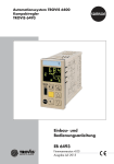
TROVIS 6493 Compact Controller
Mounting and
Operating Instructions
EB 6493 EN
®
Electronics from SAMSON
Firmware version 4.03
Edition April 2012
Definitions of the signal words used in these instructions
! DANGER!
NOTICE
indicates a hazardous situation which, if not indicates a property damage message.
avoided, will result in death or serious injury.
Note: Supplementary explanations, informatiWARNING!
on and tips
indicates a hazardous situation which, if not
avoided, could result in death or serious
injury.
2
EB 6493 EN
Contents
Contents
Page
1
Important safety instructions . . . . . . . . . . . . . . . . . . . . . . 6
2
2.1
Device version . . . . . . . . . . . . . . . . . . . . . . . . . . . . . 7
Article code. . . . . . . . . . . . . . . . . . . . . . . . . . . . . . . 7
2.2
Accessories . . . . . . . . . . . . . . . . . . . . . . . . . . . . . . . 7
3
Installation . . . . . . . . . . . . . . . . . . . . . . . . . . . . . . . 8
4
Electrical connection . . . . . . . . . . . . . . . . . . . . . . . . . . 9
5
5.1
Operation. . . . . . . . . . . . . . . . . . . . . . . . . . . . . . . 12
Display . . . . . . . . . . . . . . . . . . . . . . . . . . . . . . . . 12
5.2
Control keys . . . . . . . . . . . . . . . . . . . . . . . . . . . . . . 14
5.3
5.3.1
5.3.2
5.3.3
5.4
5.4.1
5.4.2
5.4.3
5.5
Operating level . . . . . . . . . . . . . . . . . . . . . . .
Changing the internal set point . . . . . . . . . . . . . . . .
Switching between set points . . . . . . . . . . . . . . . . .
Switching over to manual mode and changing the control output .
Setup level . . . . . . . . . . . . . . . . . . . . . . . . .
Configuring the controller . . . . . . . . . . . . . . . . . .
Key number
. . . . . . . . . . . . . . . . . . . .
Example showing configuration and parameterization . . . .
Overview of operating steps . . . . . . . . . . . . . . . . .
6
6.1
Functions of the compact controller . . . . . . . . . . . . . . . . . . 32
PAR menu: Control parameters. . . . . . . . . . . . . . . . . . . . . 32
6.2
6.2.1
6.2.2
6.2.3
6.2.4
6.2.5
6.2.6
6.2.7
6.2.8
6.3
6.3.1
6.3.2
6.4
6.4.1
6.4.2
IN menu: Input functions . . . . . . . . . . . . . . . . . . . . .
-CO- IN1:
Input signal IN1 . . . . . . . . . . . . . . .
-CO- IN2:
Input signal IN2 . . . . . . . . . . . . . . .
-CO- MEAS:
Signal monitoring. . . . . . . . . . . . . . .
-CO- MAN:
Switch to manual mode in case of signal failure
-CO- CLAS:
Assignment of X and WE to analog inputs . . .
-CO- DI.FI:
Filtering of X and WE . . . . . . . . . . . . .
-CO- SQR:
Root extraction of X and WE . . . . . . . . .
-CO- FUNC:
Function generation of X and WE . . . . . . .
SETP menu: Set point . . . . . . . . . . . . . . . . . . . . . . .
-CO- SP.VA:
Set point setting. . . . . . . . . . . . . . . .
-CO- SP.FU:
Set point functions . . . . . . . . . . . . . .
CNTR menu: Controller functions . . . . . . . . . . . . . . . . . .
-CO- C.PID:
Control algorithm . . . . . . . . . . . . . . .
-CO- SIGN:
Inversion of error XD . . . . . . . . . . . . .
.
.
.
.
.
.
.
.
.
.
.
.
.
.
.
.
.
.
.
.
.
.
.
.
.
.
.
.
.
.
.
.
.
.
.
.
.
.
.
.
.
.
.
.
.
.
.
.
.
.
.
.
.
.
.
.
.
.
.
.
.
.
.
.
.
.
.
.
.
.
.
.
.
.
.
EB 6493 EN
15
15
15
16
16
17
18
21
26
34
34
34
35
36
36
37
37
37
39
41
42
47
47
50
3
Contents
6.4.3
6.4.6
6.4.7
6.4.8
6.5
6.5.1
6.5.2
6.5.3
6.5.4
6.5.5
6.5.6
6.5.7
6.5.8
6.5.9
6.5.10
6.5.11
6.6
6.6.1
6.6.2
6.7
6.7.1
6.7.2
6.7.3
6.7.4
6.7.5
6.7.6
6.8
Assignment of the derivative-action component
to the control output. . . . . . . . . . . . . . .
-CO- CH.CA:
Control mode selection P(D)/PI(D) . . . . . . . .
-CO- M.ADJ:
Operating point preset by manual operation for
YPID . . . . . . . . . . . . . . . . . . . . . .
-CO- DIRE:
Operating direction of manipulated variable. . .
-CO- F.FOR:
Feedforward control . . . . . . . . . . . . . .
-CO- AC.VA:
Increase/decrease actual value (process variable)
OUT menu: Output functions . . . . . . . . . . . . . . . . . . . . .
-CO- SAFE:
Activate constant output value . . . . . . . . . .
-CO- MA.AU:
Manual/automatic switchover . . . . . . . . . .
-CO- Y.LIM:
Control signal limitation YPID . . . . . . . . . .
-CO- RAMP:
Output ramp/output rate limitation . . . . . . .
-CO- BLOC:
Locking manipulated variable YPID . . . . . . .
-CO- FUNC:
Function generation of manipulated variable. . .
-CO- Y.VA:
Signal range for analog output Y . . . . . . . .
-CO- Y.SRC:
Source for analog output Y . . . . . . . . . . .
-CO- CALC:
Mathematical adaptation of analog output Y . . .
-CO- C.OUT:
On/off output or three-step output. . . . . . . .
-CO- B.OUT:
Binary outputs BO1 and BO2 for status messages
ALRM menu: Limit relays . . . . . . . . . . . . . . . . . . . . . . .
-CO- LIM1:
Limit relay L1 . . . . . . . . . . . . . . . . . .
-CO- LIM2:
Limit relay L2 . . . . . . . . . . . . . . . . . .
AUX menu: Additional functions . . . . . . . . . . . . . . . . . . .
-CO- RE.CO:
Restart conditions after power failure . . . . . .
-CO- ST.IN:
Reset to default settings . . . . . . . . . . . . .
-CO- KEYL:
Lock control keys . . . . . . . . . . . . . . . .
-CO- VIEW:
Top/bottom viewing angle of display . . . . . .
-CO- FREQ:
Power line frequency (ripple filter) . . . . . . . .
-CO- DP:
Decimal separator setting . . . . . . . . . . . .
-CO- TUNE: Start-up adaptation . . . . . . . . . . . . . . . . . . .
.
.
.
.
.
.
.
.
.
.
.
.
.
.
.
.
.
.
.
.
.
.
.
.
.
.
.
52
52
52
54
55
55
55
57
57
59
61
61
61
62
62
73
74
76
76
77
77
78
78
78
79
79
80
6.9
6.9.1
6.9.2
6.9.3
6.9.4
6.9.5
I-O menu: Process data . . . . . . . . . . . . . . . . . . . . . .
-CO- CIN:
Firmware version . . . . . . . . . . . . . . .
-CO- S-No:
Serial number . . . . . . . . . . . . . . . .
-CO- ANA:
Read analog inputs and outputs . . . . . . . .
-CO- BIN:
Read binary inputs and outputs . . . . . . . .
-CO- ADJ:
Calibration of analog inputs and analog output
.
.
.
.
.
.
82
82
83
83
83
83
7
7.1
Typical applications . . . . . . . . . . . . . . . . . . . . . . . . . . 86
Temperature control . . . . . . . . . . . . . . . . . . . . . . . . . . 86
6.4.4
6.4.5
4
EB 6493 EN
-CO- D.PID:
.
.
.
.
.
.
. 50
. 50
Contents
7.2
Pressure control . . . . . . . . . . . . . . . . . . . . . . . . . . . . 91
8
8.1
Start-up . . . . . . . . . . . . . . . . . . . . . . . . . . . . . . . . 95
Tuning according to the Ziegler and Nichols method . . . . . . . . . . 96
9
Fault alarms . . . . . . . . . . . . . . . . . . . . . . . . . . . . . 100
10
Infrared interface . . . . . . . . . . . . . . . . . . . . . . . . . . 101
11
11.1
Appendix . . . . . . . . . . . . . . . . . . . . . . . . . . . . . . 103
Technical data . . . . . . . . . . . . . . . . . . . . . . . . . . . . 103
11.1
Configuration list . . . . . . . . . . . . . . . . . . . . . . . . . . . 106
11.2
Configuration protocol . . . . . . . . . . . . . . . . . . . . . . . . 124
11.3
Values for resistance thermometers . . . . . . . . . . . . . . . . . . 129
11.4
Used abbreviations. . . . . . . . . . . . . . . . . . . . . . . . . . 130
Index . . . . . . . . . . . . . . . . . . . . . . . . . . . . . . . . 131
Firmware revisions
4.01 (old)
4.02 (new)
Internal modifications
4.02 (old)
4.03 (new)
Internal modifications
EB 6493 EN
5
Important safety instructions
1
Important safety instructions
For your own safety, follow these instructions concerning the mounting, start-up and operation
of the compact controller:
4 The compact controller may only be mounted, started up or operated by trained and ex-
perienced personnel familiar with the product.
According to these Mounting and Operating Instructions, trained personnel refers to individuals who are able to judge the work they are assigned to and recognize possible
dangers due to their specialized training, their knowledge and experience as well as
their knowledge of the relevant standards.
4 The controller is intended for use in low-voltage installations.
For wiring and maintenance, you are required to observe the relevant safety regulations.
To avoid damage to any equipment, the following also applies:
4 Proper shipping and appropriate storage are assumed.
6
EB 6493 EN
Device version
2
Device version
2.1
Article code
TROVIS 6493-032
Compact Controller
Power supply
90 to 250 V AC
24 V AC/DC
2.2
x
4
5
Accessories
Accessories
Order no.
TROVIS-VIEW Configuration
and Operator Interface.......... 6661*
Infrared adapter (RS-232)...... 8864-0900
Bracket for infrared adapter... 1400-9769
USB to RS-232 adapter.......... 8812-2001
* The TROVIS-VIEW software is a common
operator interface for various smart
SAMSON devices. The software together
with a device-specific module allow the configuration and parameterization of the device.
The
device-specific
module
for
TROVIS 6493 can be downloaded free of
charge from the SAMSON website (Services > Software > TROVIS-VIEW).
Additional information on TROVIS-VIEW
(e.g. system requirements) can found on the
SAMSON website and in the Data Sheet
T 6661 EN.
7
Installation
3
Installation
The TROVIS 6493 Compact Controller is designed for panel mounting. Its front case has the dimensions 48 x 96 mm.
1.
Prepare a panel cut-out with the dimensions 45+0.6 x 92+0.8 mm.
2.
Push the compact controller into the panel cut-out from the front.
3.
Insert supplied mounting clips (2) in the notches on the top and bottom (Fig. 1).
4.
Turn the threaded rods in the direction of the control panel using a screwdriver, clamping the case against the control panel.
2
Installation depth
including terminals:
158 (6.18)
1
1 Compact controller
3
2 Mounting clip
3 Control panel
2
Fig. 1 · Installation · Dimension in mm (inch)
8
EB 6493 EN
Electrical connection
4
Electrical connection
! Risk of electric shock!
When installing electric cables, you are required to observe the regulations governing electrical
power plant installation in the country where the controller is to be installed.
Installation notes
4 Install the power supply lines and the signal lines separately! Do not install them parallel to
each other! To improve noise immunity, observe a minimum distance of 10 cm between the
power cable and the measuring input lines.
To avoid measurement errors or other disturbances, use shielded cables for the analog and
binary signal lines. Ground the shield at one end, either at the controller inlet or at the control cabinet outlet, using the largest possible cross-section. Connect the central grounding
point and the PE grounding conductor with a cable ≥ 10 mm² using the shortest route.
Inductances in the control cabinet, e.g. contactor coils, are to be equipped with suitable interference suppressors (RC elements).
Control cabinet elements with high field strength, e.g. transformers or frequency converters,
are to be shielded with separators providing a good ground connection.
The controller has screw terminals for 1.5 mm² wires (0.5 to 1.5 mm² wire cross-section).
4
4
4
The lines are connected to the terminal strips 1 and 2 as shown in the following wiring diagram
(Fig. 2).
Transmitter supply
The controller has a supply output to power a maximum of two two-wire transmitters (20 V DC,
45 mA) and the binary input.
Resistance thermometers
The analog inputs IN1 and IN2 are designed for the connection of resistance thermometers Pt
100 and Pt 1000 in a three-wire circuit. The resistance of each connection lead must be the
same and not exceed 15 Ω. Lead calibration is not necessary.
Resistance thermometers can also be connected in two-wire circuits. In this case, connect a
jumper between the controller terminals. Take into account that the lead resistance may reach
several ohms over long distances, causing the measured value to be considerably distorted. This
measured value can be compensated for by a correction value. Refer to section 6.4.7 (-COF.FOR Feedforward control) on page 52.
EB 6493 EN
9
Electrical connection
Potentiometers
The analog inputs IN1 and IN2 are designed for the connection of a potentiometer with
two-wire or three-wire connection.
A potentiometer is used, for example for position feedback of an electrical actuator or for input
of an external set point.
Generally for potentiometers, we recommend performing a zero and span calibration. Refer to
section 6.9.5 (-CO- ADJ Calibration of analog inputs and analog output) on page 83.
10
EB 6493 EN
Electrical connection
Current
Current
Two-wire
transmitter
Voltage
0/4...20 mA
4...20 mA
0/2...10 V
12
13
Pt 100/Pt 1000
Ni 100/Ni 1000
1000 Ω
Three-wire Two-wire
Three-wire
+
11
Analog input
IN1
Potentiometer
Resistance
thermometer
–
+
+
–
–
Two-wire
100 %
ϑ
100 %
ϑ
0%
0%
–
14
Supply output
20 V, max. 45 mA 15 +
+
17
Analog input
IN2
19
20
Analog output
Binary input
BI1
Binary
output
BO3
Supply
voltage
31
32
81
82
83
+
–
–
+
–
+
Binary
output
BO2
100 %
ϑ
0%
0%
+
–
–
24 V DC
+
+
+
–
–
–
3...50 V DC,
max. 30 mA
84
L
L
N
N
L/+
(90...250 V AC)
N/–
Three-step output
for electric actuator
Binary
output
BO1
100 %
ϑ
On/off
output
24 V AC/DC (20...30 V)
Binary output
Limit relay
BO1
LIM 1
BO2
LIM 2
41
43
+
51
L'(+)
N
52
53
L
L
42
–
Fig. 2 · Electrical connection
EB 6493 EN
11
Operation
5
Operation
The TROVIS 6493 Compact Controller is a microprocessor-controlled compact controller with a
flexible software concept for the automation of industrial and processing plants. The controller is
suitable for use in simple control loops as well as for solving more complex control tasks. The
flexible software concept allows the user to configure control circuits without modifying the
hardware. The functions are stored in a read-only memory and can be adapted to the specific
requirements of the respective control system.
Configuration, parameterization and operation of the TROVIS 6493 Compact Controller can
be performed either directly using the keys on the front panel (refer to section 5.2) or using the
TROVIS-VIEW Configuration and Operator Interface (see section 10).
Principally, there are two levels which provide different key functions and different displays: the
operating level and the setup level. The readings in the display (see section 5.1) and the functions of the keys (see section 5.2) differ depending on which level the controller is in.
5.1
Display
No.
Operating level
Setup level
Depending on the level selected, the following variables and operating states are shown on the display:
1
Controlled variable X
2
Value assumed by W, W2, WE, Y or Xd
Designations, settings and values
of the functions and parameters
(→ section 11.1)
3
Limit relay L2 active
Not displayed
4
Three-step output –
Not displayed
5
Limit relay L1 active
Not displayed
6
Three-step output + or on/off output
Not displayed
7
Fault alarms (see section 6.2.3)
Not displayed
8
Hand icon displayed in manual mode,
no icon in automatic mode
Not displayed
9
Press
key to display W, W2, WE, Y or Xd%
in sequence. The associated value appears in (2).
W2 and WE only when they have been
activated (see section 6.3.1).
Fast access to parameters:
Every time you press , the decimal point of a parameter is shifted
one place to the right.
Bar display of Xd in percent
Not displayed
10
12
EB 6493 EN
Operation
17
1
10
2
9
Xd%
W2
WE
3
8
L1
L2
4
7
5
6
13
12
14
18
11
15
16
1
Controlled variable X
7 Fault alarm
12 Selector key
2
W, W2, WE, Y
or XD
8 Hand icon
13 Manual/automatic key
9 After pressing
W, W2, Y or XD is
shown with the value in 2
14 Cursor key
(increase, scroll forwards)
3
Limit relay L2 active
4
Three-step output –
5
Limit relay L1 active
10 Bar reading of XD in %
16 Escape key
6
Three-step output +
11 Enter key
17 Label (exchangeable)
15 (decrease, scroll backwards)
18 Infrared interface
EB 6493 EN
13
Operation
5.2
Control keys
The keys' function varys depending on which level the controller is in.
Key
Enter key
(yellow)
Selector
key
Operating level
Setup level
– Access setup level
– Activate set point*
– Open menus, functions
and parameters
– Confirm settings
* Only if the set point name (W, W2 or WE)
blinks on the display
– Switch between readings:
W Internal set point 1
W2* Internal set point 2
WE* External set point
Y
Manipulated variable
Xd% Error
* Only when they have been configured
(see section 6.3.1)
– Change from manual to automatic mode
and vice versa*
Manual/
automatic
key
* In manual mode, the hand icon
display.
Cursor keys
– Change the value of internal set point*
– Change the control output**
** Only when Y has been selected using the
selector key or when manual mode ( ) has
been selected.
– Return to the operating
level stepwise
After approx. 5 minutes, the reading on the
display changes back to the currently valid
set point
Changes back to operating
level after approx. 5 minutes
Exception: in manual mode and when the manipulated
variable is displayed
EB 6493 EN
– Browse within menus,
functions and parameters
– Change function settings
and parameter values
– Display currently valid set point
Escape key
14
No function
appears in the
* Only when selected using the selector key.
No keys
pressed
– Access parameter level
– Jump within the value
range in the parameter
level
– Shift the decimal point one
place to the right
Operation
5.3
Operating level
The controller is in this level when control operation is active. Key information on the control
process are displayed in this level. The default display shows the controlled variable X, error
signal Xd, the currently valid set point W, W2 or WE, the active limit relay as well as information on the three-step output, if applicable.
Note: Other variables, such as the error in %, can be displayed instead of the currently valid set
point. To do this, press the selector key
until the required variable is displayed. The following
variables can be selected: internal set point W, manipulated variable Y, error Xd% and, depending on the configuration in the SETP menu, the internal set point W, W2 and the external
set point WE.
The following actions can be performed in the operating level:
– Changing the internal set point (→ section 5.3.1).
– Switching between set points (→ section 5.3.2).
– Switching to the manual mode and changing the control output (→ section 5.3.3).
5.3.1 Changing the internal set point
Select internal set point W or W2.
Increase the set point.
Decrease the set point.
5.3.2 Switching between set points
Select set point W, W2 or WE.
If a set point is not active, the set point name (W, W2 or WE) blinks on the display.
Activate the set point.
The set point name (W, W2, WE) stops blinking.
The previously active set point is deactivated.
EB 6493 EN
15
Operation
5.3.3 Switching over to manual mode and changing the control output
Switch to manual mode.
The hand icon
and the control output Y (manipulated variable) appear on the
display.
Increase the manipulated variable.
Reduce the manipulated variable.
Return to automatic mode
Return to automatic mode.
The hand icon is no longer displayed. The currently valid set point is shown on the display.
Note: If required, you can display the control output (manipulated variable) Y by pressing the
key.
5.4
Setup level
This level enables you to adapt the compact controller to the control task. You can adapt preset
functions to your specific needs and change parameters. The functions are arranged in nine
main menus:
– PAR:
Control parameters
– IN:
Input
– SETP: Set point
– CNTR: Controller
– OUT: Output
– ALRM: Limit relays
– AUX: Additional functions
– TUNE: Start-up adaptation
– I-O:
Process data
Section 11.1 describes all the menus, functions and parameters.
16
EB 6493 EN
Operation
5.4.1 Configuring the controller
To set a function or parameter, you need to know the abbreviated code used for the function/parameter and the menu where it can be found. Refer to section 11.1 for an overview of
these codes. Section 5.4.3 describes an example on how to configure the controller.
To proceed:
The controller is in the operating level.
Open the setup level.
Display: PAR (Control parameters menu)
If the function you want to configure is located in a different menu:
Select the required menu: IN, SETP, CNTR, OUT, ALRM, AUX, TUNE or I-O
Open menu.
Display: -CO- and abbreviated code of the first function in the current menu
If you want to configure a different function:
Select the required function.
Open the function.
Display: Current function setting
Activate the function's editing mode.
Current function setting blinks.
Note: Every time you go to the first function after opening the setup level, you are prompted
to enter the key number (display: - - - - and KEY). You only need to enter the key number
if a key number has already been assigned to the controller (→ section 5.4.2). If this is
not the case, entry of the key number can be skipped by pressing the enter key ( ).
Change function setting.
Confirm setting.
Go to the parameter level.
Display: -PAOpen the parameter level.
Display: code of the first parameter
If you want to configure a different parameter:
Select the required parameter.
EB 6493 EN
17
Operation
Activate the parameter's editing mode.
The code for the function's parameter blinks.
Change parameter setting.
Confirm setting.
After completing all parameter settings:
Press until the controller is back in the operating level.
Note: The controller automatically returns to the operating level five minutes after the last key
has been pressed.
5.4.2 Key number
The compact controller can be operated with or without a key number. Factory default allows
the controller to be operated without a key number. Operation with a key number is only activated after a user-defined key number has been assigned. The service key number is required to
define a user-defined key number.
Note: The overriding service key number is specified at the end of the printed Mounting and
Operating Instructions. This key number allows you to change configuration settings and parameter values regardless of the user-defined key number.
We recommend removing the page containing the service key number or making it unreadable
to prevent misuse.
18
EB 6493 EN
Operation
Prompt for key number
Every time you go to the first function or parameter after opening the setup level, you are
prompted to enter the key number:
KEY blinks.
Note: When this reading appears, you can change the user-defined key number. See 'Activate/deactivate operation with key
number'.
Operation without key number
Exit prompt for key number.
Operation with key number
Enter the valid key number. In this example it is 12.
Exit prompt for key number.
Note: If you enter an incorrect key number, you are prompted
again to enter the key number. In this case, a '1' appears on the
display instead of - - - -.
Activate/deactivate operation with key number
The controller is in the operating level.
The reading on the display looks like this.
EB 6493 EN
19
Operation
Open the setup level.
Open the parameter level.
Activate prompt for key number.
KEY blinks.
Enter the service key number.
Confirm the service key number.
Display: - - - - and KEYP
Note: A number instead of - - - - means that a key number is already active. The reading shown is the valid key number.
20
EB 6493 EN
Operation
Enter your own key number (12 in this example).
Note: To deactivate operation with key number, select - - - - in the
display.
Exit prompt for key number.
The controller returns to the setup level.
Press until the controller is back in the operating level.
5.4.3 Example showing configuration and parameterization
The compact controller is to configured to be a PID controller. The associated proportional-action coefficient (KP) is to be set to 1.5. Refer to the overview in section 11.1. This overview shows
that time behavior is determined by the C.PID function in the CNTR menu.
→....
Menu
→.......................
↓ or
→..................................................
→………..…
Setting
options*
Function
description
Parameter level
-PA-
C.PID
P CP.YP
P
C.PID/CP.YP
Control algorithm
PI CP.YP
PI
C.PID/CP.YP
Pd CP.YP
PD
C.PID/CP.YP
PId CP.YP
PID
C.PID/CP.YP
PPI CP.YP
P²I
C.PID/CP.YP
Function -CO-
Control structure and functions
CNTR
* The default setting is written in bold.
EB 6493 EN
21
Operation
The proportional-action coefficient is set using the KP parameter.
↓ or
→..................................................
Parameter Parameter
selection
description
.
↓ and
, followed by
↵
Refer to
section
Value range*
KP
Proportional-action coefficient
[0.1 … 1.0 … 100.0]
TN
Reset time
[1 … 120 … 9999 s]
TV
Derivative-action time
[1 … 10 … 9999 s]
TVK1
Derivative-action gain
[0.10 … 1.00 … 10.00]
Y.PRE
Operating point
[–10.0 … 0.0 … 110.0]
DZXD
Dead zone error XD
[0.0 … 110.0 %]
DZXD
Minimum effective error XD
DZXD
Maximum effective error XD
[–110.0 % …
[
DZXD]
DZXD … 110.0 %]
The controller is in the operating level.
The reading on the display looks like this.
Open the setup level.
Display: PAR (Control parameters menu)
3x
22
EB 6493 EN
Select CNTR (Controller).
6.4.1
Operation
Enter menu.
Display: -CO- and C.PID (first function in CNTR menu)
Open function.
Display: PI (current setting of C.PID function)
Activate the function's editing mode.
Display: prompt for key number
Only for operation with key number:
Enter the valid key number (27 in the example).
Exit prompt for key number.
The CP.YP function can be edited.
PI blinks.
EB 6493 EN
23
Operation
2x Change the PI control algorithm to PID algorithm.
Confirm setting.
The editing mode is exited.
Change to the parameter level.
Display: -PA- and C.PID/CP.YP blink in alternating sequence
Open the parameter level:
Display: KP (the first parameter of the C.PID function)
Activate the parameter's editing mode.
KP blinks.
24
EB 6493 EN
Operation
Change the proportional-action coefficient KP to 1.5.
Confirm setting.
The editing mode is exited.
Note: If you want to change other parameters in the function setting, select these parameters ( ) and repeat the steps in the
gray-shaded backgroand.
4x Return to the operating level.
EB 6493 EN
25
Operation
5.5
Overview of operating steps
In following, the operation of the controller is shown in schematic form:
1
Open setup level
2
Enter menu
3
Select function/parameter
4
Display setting
5
Activate the editing mode to change setting
6
Change setting
7
Confirm setting
8
Open parameter level
1)
26
Every time you open the setup level and before you activate the editing mode for the first
time, you are prompted to enter the key number. If settings are to be made without entering
the key number, press the enter key again to activate the editing mode. Configuration is enabled until you exit the setup level.
EB 6493 EN
1
Oper.
level
2
PAR
3
5
6
1.0
KP
1)
1.0
KP
1.0
TN
1)
120
TN
7
Set control
parameters
3
-PAIN1
8
2
IN
3
-COIN1
4
6
4-20
mA
5
1)
4-20
mA
0 -10
V
5
6
0.0
IN1
1)
0.0
IN1
100.0
IN1
1)
100.0
IN1
7
7
Input IN1
Set input signal
and measuring
range
EB 6493 EN
27
28
EB 6493 EN
100
PT
-COIN2
3x
1)
0.0
IN2
1)
0.0
IN2
100
PT
100.0
IN2
1)
100.0
IN2
Input IN2
Set input signal
and measuring
range
1000
PT
3x
-COCLAS
-PAIN2
In2
X
1)
In2
X
In1
X
In1
WE
1)
In1
WE
In2
WE
Assign input variables
-COSP.VA
SETP
on
W
-COC.PID
CNTR
PI
CP.YP
1)
-PAW
0.0
W
1)
0.0
W
-PAC.PID
1.0
KP
1)
1.0
KP
PI
CP.YP
120
TN
1)
120
TN
2x
5x
Set control
behavior
2x
PId
CP.YP
5x
-CODIRE
Adjust
set point
dir.d
DI.AC
1)
dir.d
DI.AC
EB 6493 EN
in.d
DI.AC
Set operating
direction
29
30
EB 6493 EN
-COSAFE
OUT
6x
6x
-COY.VA
4-20
mA
Analog output:
Set signal range
4-20
mA
1)
0 -10
V
3x
3x
-PAC.OUT
1.0
KPL1
8x
-COC.OUT
oFF
2/3.S
60
TY
oFF
2/3.S
1)
2x
2x
i.Fb
3.STP
8x
1)
60
TY
Set three-step output
ALRM
AUX
TUNE
I-O
-CORE.CO
F02
MODE
1)
F02
MODE
F01
MODE
Set restart conditions
after power failure
EB 6493 EN
31
Functions of the compact controller
6
Functions of the compact controller
In this section, all functions of the setup level are described. There are nine menus in the setup
level which contain the functions and their parameters. Each menu is dedicated to the functions
of a certain topic:
–
–
–
–
–
–
–
–
–
PAR:
IN:
SETP:
CNTR:
OUT:
ALRM:
AUX:
TUNE:
I-O:
Control parameters
Input
Set points
Controller
Output
Limit relays
Additional functions
Start-up adaptation
Process data
Section 11.1 contains an overview of all the menus, functions and parameters.
Functions are identified in the display by -CO-, whereas the parameter level is identified by
-PA-.
Functions of the binary input BI1
– SETP menu
– SETP menu
– CNTR menu
-CO- SP.FU/RAMP
-CO- SP.FU/CH.SP
-CO- AC.VA
–
–
–
–
–
-CO- SAFE
-CO- MA.AU
-CO- RAMP
-CO- BLOC
-CO- B.OUT
OUT menu
OUT menu
OUT menu
OUT menu
OUT menu
6.1
PAR menu:
Start set point ramp (→ section 6.3.2)
Switch over set points (→ section 6.3.2)
Increase/decrease actual value
(process variable) (→ section 6.4.8)
Activate constant output value (→ section 6.5.1)
Manual/automatic switchover (→ section 6.5.2)
Start output ramp (→ section 6.5.4)
Locking manipulated variable (→ section 6.5.5)
Activate binary outputs (→ section 6.5.11)
Control parameters
This menu does not contain any functions. When you open this menu, the controller immediately
jumps to the parameter level -PA-. It allows you to quickly set the control parameters.
Note: The control parameters can also be set in the CNTR menu (C.PID function). Refer to section 6.4.1.
32
EB 6493 EN
Fig. 3 · IN menu
I–O
IN
IN
I–O
IN
ALRM
IN1
Input
assignment
A
Dig. filter
WE
D
IN1
DI.FI[WE]
CLAS[WE]
X
D
IN2
Signal
monitoring
IN2
CLAS[X]
F
DI.FI[X]
Function gen.
MAN
LIM2
LIM1[L1.WE]
LIM2[L2.WE]
LIM1
LIM2
LIM1[L1.X]
LIM2[L2.X]
WE
SQR[WE]
WE.VA
FUNC[WE]
X
SQR[X]
FUNC[X]
CO.VA
MEAS
LIM1
EB 6493 EN
33
Functions of the compact controller
A
F
Root ext.
Functions of the compact controller
PAR
6.2
KP
Proportional-action
coefficient
[0.1 … 1.0 … 100.0]
TN
Reset time
[1 … 120 … 9999 s]
TV
Derivative-action time
[1 … 10 … 9999 s]
Y.PRE
Operating point
[–10.0 … 0.0 … 110.0 %]
IN menu:
Input functions
The analog inputs (IN1, IN2) are set in the IN menu.
6.2.1 -CO- IN1:
Input signal IN1
This function enables you to define the input signal type and range for the analog input IN1.
IN
-CO- IN1
Input signal IN1
0–20 mA
0 to 20 mA
4–20 mA
4 to 20 mA
0–10 V
0 to 10 V
2–10 V
2 to 10 V
100 PT
Pt 100 (–100 … 500 °C)
Resistance values → section 11.3
1000 PT
Pt 1000 (–100 … 500 °C)
Resistance values → section 11.3
100 NI
Ni 100 (–60 … 250 °C)
Resistance values → section 11.3
1000 NI
Ni 1000 (–60 … 250 °C)
Resistance values → section 11.3
0–1KOHM
0 to 1000 Ω
-PA- IN1
IN1
Lower measuring range value
[–999.0 … 0.0 …
IN1
Upper measuring range value
[
6.2.2 -CO- IN2:
IN1]
IN1 … 100.0 … 9999]
Input signal IN2
This function enables you to define the input signal type and range for the analog input IN2.
34
EB 6493 EN
Functions of the compact controller
IN
-CO- IN2
Input signal IN2
0–20 mA
0 to 20 mA
4–20 mA
4 to 20 mA
0–10 V
0 to 10 V
2–10 V
2 to 10 V
100 PT
Pt 100 (–100 … 500 °C)
1000 PT
Pt 1000 (–100 … 500 °C)
Resistance values → section 11.3
Resistance values → section 11.3
100 NI
Ni 100 (–60 … 250 °C)
Resistance values → section 11.3
1000 NI
Ni 1000 (–60 … 250 °C)
Resistance values → section 11.3
0–1KOHM
0 to 1000 Ω
-PA- IN2
IN2
Lower measuring range value
[–999.0 … 0.0 …
IN2
Upper measuring range value
[
IN2]
IN2 … 100.0 … 9999]
6.2.3 -CO- MEAS: Signal monitoring
This function enables you to define whether the signal ranges of the analog inputs IN1 and IN2
are to be monitored either for a signal exceeding or falling below the signal range.
When the signal exceeds or falls below the rated signal range, the fault alarm output (BO3) is
activated and the alarm icon
appears on the display. In addition, the signal violation is indicated by one of the following readings blinking on the display:
__o1:
Signal exceeds the rated signal range at analog input IN1 or at analog inputs
IN1 and IN2
__u1:
Signal falls below the rated signal range at analog input IN1 or at analog inputs IN1 and IN2
__o2:
Signal exceeds the rated signal range at analog input IN2
__u2:
Signal falls below the rated signal range at analog input IN2
4
4
4
4
Note: The controller can be configured to change to the manual mode when a signal range violation occurs. Refer to section 6.2.4.
IN
-CO- MEAS
Signal monitoring
oFF ME.MO
Off
IN1 ME.MO
Analog input IN1
IN2 ME.MO
Analog input IN2
ALL ME.MO
Analog input IN1 and IN2
EB 6493 EN
35
Functions of the compact controller
6.2.4 -CO- MAN:
Switch to manual mode in case of signal failure
This function enables you to define whether the controller automatically switches to manual
mode
after a signal range violation when the signal range monitoring is active (-CO- MEAS
≠ oFF ME.MO).
4 F01 FAIL: The controller switches to manual mode and the output value Y1K1 is issued.
The output value Y1K1 only becomes effective when the controller is in automatic mode
at the time when the signal range violation occurred.
4 F02 FAIL: The controller switches to manual mode and the last manipulated variable is
issued.
In manual mode, the output value can be changed using the cursor keys ( and ). The
controller can first change back to automatic mode when the signal range violation no longer
exists.
IN
-CO- MAN
Switch to manual mode in case of signal failure
oFF FAIL
Off
F01 FAIL
With output value Y1K1
F02 FAIL
With last manipulated variable value
-PA- MAN
Y1K1
Constant output
[–10.0 … 110.0 %]
Note: The Y1K1 parameter can also be defined in -CO- SAFE and -CO- RE.CO functions. Refer
to sections 6.5.1 and 6.7.1.
6.2.5 -CO- CLAS:
Assignment of X and WE to analog inputs
Internally, the compact controller operates with the analog input signals X and WE. The CLAS
function is used to assign these signals to the analog inputs IN1 or IN2. By default, X is assigned
to analog input IN2 and WE to analog input IN1.
IN
-CO- CLAS
Assignment of X to analog inputs
In2 X
X = IN2
In1 X
X = IN1
Assignment of WE to analog inputs
36
In1 WE
WE = IN1
In2 WE
WE = IN2
EB 6493 EN
Functions of the compact controller
6.2.6 -CO- DI.FI:
Filtering of X and WE
This function enables you to determine whether X and/or WE are to be filtered.
The first-order filter (low-pass filter or Pt1 behavior) smooths the selected signals and suppresses
input signal interferences of higher frequency. The time constant of the Pt1 element is defined by
the TS.X parameter for the input signal X, and by TS.WE for the input signal WE.
IN
-CO- DI.FI
Filtering of input variable X
oFF X
Off
on X
On
TS/X
Time constant of X filter
[0.1 … 1.0 … 100.0 s]
Filtering of input variable WE
oFF WE
Off
on WE
On
TS.WE
Time constant of WE filter
6.2.7 -CO- SQR:
[0.1 … 1.0 … 100.0 s]
Root extraction of X and WE
This function performs a root extraction of the input variables and internally standardizes them
between 0 to 100 %: X' = 10 ⋅ X and WE' = 10 ⋅ WE.
The root extraction function is used for flow rate measurement by an orifice plate assembly to
calculate the flow rate from a measured differential pressure.
IN
-CO- SQR
Root extraction of X
oFF X
Off
on X
On
Root extraction of WE
oFF WE
Off
on WE
On
6.2.8 -CO- FUNC:
Function generation of X and WE
The function generation is used to revaluate an input signal to allow further processing. This
function makes it possible to adapt auxiliary, reference or equivalence variables, inherent in
measurement or industrial processes, for the control circuit or to perform a linearization. This
can be performed when the correlation between the input signal and the required new output
EB 6493 EN
37
Functions of the compact controller
signal is known (i.e. due to scientific laws, empirical data or measured data). Examples include
the correlation between steam pressure and temperature.
Seven coordinates exist for function generation. Each coordinate is defined by an input value
and an output value.
4 Numerical values (e.g. in °C or bar) are entered
4 The parameters MIN and MAX are used to determine the measuring range of the output sig4
nal E'. If K1.Y or K7.Y do not agree with MIN and MAX, the output values for the function-generated signal, which are below or above these limits, are constantly set to K1. Y or
K7.Y.
The compact controller completes the polygonal curve by generating straight lines (Fig. 4). If
you have entered an output value greater than MAX or smaller than MIN, it will be set to the
value of MAX or MIN. Section 7 shows an example of function generation.
MIN
E'
MAX
MAX
K7.Y
E
E'
K5.Y
K1.Y
MIN
K1.Y
K5.Y
K7.Y
K1.X
K5.X
K6.X
K7.X
E
K1.X
K5.X K6.X K7.X
E
E'
Lower range value of output
signal
Upper range value of
output signal
Output value 1
Output value 5
Output value 7
Input value 1
Input value 5
Input value 6
Input value 7
Signal before function
generation (input signal)
Signal after function
generation (output signal)
Fig. 4 · Function generation
Note:
– We recommend creating a table or to plot the curve in a Cartesian coordinate system. The
seven points for function generation must be selected to be able to plot the curve properly.
The controller calculates a straight line between points. Seven points must be defined even if
the signal course can be plotted sufficiently with less than seven points. If necessary, enter the
first points or the last points to be the same.
38
EB 6493 EN
Functions of the compact controller
– The polygonal chain of the curve is not restricted. Polygonal curves with more than one maximum or minimum are possible. However, make sure that only one output value is assigned
to an input value. Otherwise, the input signal cannot be clearly assigned to a value.
IN
-CO- FUNC
Function generation of X
oFF X
Off
on X
On
-PA- FUNC/X
MIN
Lower range value of output signal
[–999.0 … 0.0 … MAX]
MAX
Upper range value of output signal
[MIN … 100.0 … 9999]
K1.X
Input value 1
[
K1.Y
Output value 1
[MIN … MAX]
…
…
…
K7.X
Input value 7
[
K7.Y
Output value 7
[MIN … MAX]
IN1 …
IN2 …
IN1 …
IN2 …
IN1;
IN2]
IN1;
IN2]
Function generation of WE
oFF WE
Off
on WE
On
-PA- FUNC/WE
6.3
MIN
Lower range value of output signal
[–999 … 0.0 … MAX]
MAX
Upper range value of output signal
[MIN … 100 … 9999]
K1.X
Input value 1
[
K1.Y
Output value 2
[MIN … MAX]
…
…
K7.X
Input value 7
[
K7.Y
Output value 7
[MIN … MAX]
SETP menu:
IN1 …
IN2 …
IN1 …
IN2 …
IN1]
IN2]
IN1]
IN2]
Set point
This menu enables enables you to determine the functions of a set point. The compact controller
has two internal set points W and W2 as well as an external set point WE.
EB 6493 EN
39
SETP
I–O
FE.CO
SP.CO
Set point setting
WE
WE
W
W
W2
W2
Set point
ramp
RAMP
BI
SP.FU
CH.SP
W/W2/WE
SP.FU
SP.VA
Functions of the compact controller
EB 6493 EN
Fig. 5 · SETP menu
40
I–O
Functions of the compact controller
6.3.1 -CO- SP.VA: Set point setting
This function enables you to define which set point W2 or WE is activated. The internal set point
W is always active. The set point and its measuring range can be determined in the parameter
level. The measuring range ( WINT, WINT) must be identical to the measuring range of the
controlled variable X ( IN1, IN1 or IN2, IN2) or it must be identical to the output
range (MIN, MAX) when function generation is active. The internal set points W and W2 can
only be adjusted within the upper and lower adjustment limits ( WRAN, WRAN).
Function of input variable WE:
4 on WE: WE is used as the external set point
4 F01 WE: WE is used for external position feedback with three-step output (see section
6.5.10). In this setting, WE is not displayed in the operating level. The reading is shown
only in the I-O menu, (see section 6.9.3).
4 F02 WE: WE is used for feedforward control (see section 6.4.7). In this setting, WE is not
displayed in the operating level. The reading is only shown in the I-O menu, (see section
6.9.3).
SETP
-CO- SP.VA
Internal set point W
on W
On
-PA- SP.VA/W
Internal set point
[
WINT
Lower measuring range value
W/W2
[–999 … 0.0 …
WINT
Upper measuring range value
W/W2
[
WINT … 100.0 … 9999]
WRAN
Lower adjustment limit W/W2
[
WINT … 0.0…
WRAN
Upper adjustment limit W/W2
[
WRAN … 100.0 …
[
WRAN … 0.0 …
W
WRAN … 0.0 …
WRAN]
WINT]
WRAN]
WINT]
Internal set point W2
oFF W2
Off
on W2
On
-PA- SP.VA/W2
W2
Internal set point 2
WRAN]
Input variable WE
EB 6493 EN
41
Functions of the compact controller
oFF WE
Off
on WE
External set point WE
F01 WE
Input for external feedback with three-step output
F02 WE
Input for feedforward control
6.3.2 -CO- SP.FU:
Set point functions
6.3.2.1 -CO- SP.FU/RAMP Set point ramp
A set point ramp is particularly suited for closed-loop controlled systems which do not tolerate
rapidly changing set points. The ramped transition from one set point to another helps to avoid
hunting. In the set point ramp, the set point at the comparator SP.CO runs according to the adjusted running time at a constant rate from the initial set point to the target set point. Depending
on how the -CO- SP.FU function is configured, the ramp starts either using the current value of
the controlled variable X at the comparator, the initial value WIRA or another set point.
The running time of the set point ramp is determined for the entire measuring range ( WINT to
WINT) by the TSRW parameter. When the set point changes from a value W to a new value
W2, the actual running time of the set point ramp is the time t1, as illustrated in Figs. 7 and 8.
The value for the TSRW parameter can be calculated as follows:
TSRW = t1 ⋅
WINT − WINT
W2 − W
4 F01 RAMP – Start set point ramp with the controlled variable at the comparator: This
ramp function is started by a binary input. An active binary input causes the set point at
comparator SP.CO to adopt the same value as the current value of the controlled
variable at comparator X. A signal change at the binary input from ‘1’ (active) to ‘0’ (inactive) starts the ramp and the set point runs until it reaches the target set point (internal
or external set point). After reaching the target set point, the ramp stops. After this, the
set point at comparator SP.CO follows the target set point (e.g. W) without delay.
If the controller is switched to manual mode while the ramp is running, the ramp is
stopped and the set point adopts the same value as the controlled variable X. After
switching back to automatic mode, the ramp continues to run again until reaching the
target set point. If the binary input is activated again while the ramp is running, the set
point at comparator SP.CO returns to the current value at comparator X (retriggering).
If the controller starts after the power supply has been interrupted for more than one second in automatic mode, the set point at comparator SP.CO adopts the same value as at
the comparator when the binary input is active and the target set point when the binary
input in not active.
42
EB 6493 EN
Functions of the compact controller
SP.CO
X
WINT
W
SP.CO
X
WINT
t1
t
TSRW
[s]
BI
1
0
t
[s]
Man
Aut o
t
[s]
WINT Lower measuring range value
WINT Upper measuring range value
TSRW
Running time of the set point
ramp
t1
Actual running time of the set
point ramp
Fig. 6 · Start set point ramp by binary input, SP.CO = X
4 F02 RAMP – Start set point ramp with initial set point: This ramp function is started by
the binary input. An active binary input causes the set point at comparator SP.CO to be
set to the entered initial set point WIRA. A signal change at the binary input from ‘1’ (active) to ‘0’ (inactive) starts the ramp and the set point runs until it reaches the target set
point (internal or external set point). After reaching the target set point, the ramp stops.
After this, the set point at comparator SP.CO follows the target set point (e.g. W) without
delay.
If the controller is switched to manual mode while the ramp is running, the ramp is
stopped and the set point at comparator SP.CO adopts again the same value as the controlled variable X.
After switching back to automatic mode, the ramp continues to run again until reaching
the target set point. If the binary input is activated again while the ramp is running, the
set point at comparator SP.CO returns to the current value at comparator X
(retriggering).
If the controller starts after the power supply has been interrupted for more than one second in automatic mode, the set point at comparator SP.CO adopts the start set point
WIRA when the binary input is active and the target set point when the binary input in
not active.
EB 6493 EN
43
Functions of the compact controller
SP.CO
X
WINT
W
SP.CO
X
WIRA
WINT
t1
t
TSRW
[s]
BI
1
0
t
[s]
Man
Auto
t
[s]
WINT Lower measuring range value
WINT Upper measuring range value
TSRW
Running time of the set point
ramp
WIRA
Initial value
t1
Actual running time of the set
point ramp
Fig. 7 · Start set point ramp by binary input, SP.CO = WIRA
4 F03 RAMP – Set point continuously active (without start condition): The ramp function
in this setting is continuously active. Every change of the set point causes a ramped
change of the set point at comparator SP.CO even after switchover between set points.
The diagram shows the set point ramp (SP.CO) during a switchover between set points
W and W2 (additional settings: -CO- SP.VA = on W2 and -CO- SP.FU = F01 CH.SP)
initiated by the binary input.
If the controller is switched to manual mode while the ramp is running, the ramp is
stopped and the set point at comparator SP.CO adopts the current value at comparator
X. After switching back to automatic mode, the ramp continues to run again until reaching the target set point. If the controller starts after the power supply has been interrupted
for more than one second in automatic mode, the set point at comparator SP.CO adopts
the target set point.
44
EB 6493 EN
Functions of the compact controller
SP.CO
X
WINT
W2
W
WINT
SP.CO
X
t1
t1
t
TSRW
TSRW
[s]
BI
1
0
t
[s]
Man
Auto
t
WINT Lower measuring range value
WINT Upper measuring range value
TSRW
Running time of the set point
ramp
t1
Actual running time of the set
point ramp
[s]
Fig. 8 · Set point continuously active
6.3.2.2 -CO- SP.FU/CH.SP Set point switchover by binary input
This functions enables you to determine the conditions for switching between the internal and
external set point.
4 oFF CH.SP: No set point switchover
4 F01 CH.SP: Switchover between active internal and external set points initiated by binary input BI (W/W2 to WE)
WE is active when the binary input is active.
4 F02 CH.SP: Switchover between the internal set points initiated by binary input BI (W to
W2).
W2 is active when the binary input is active.
W is active when the binary input is not active.
The -CO- SP.VA function must not be set to 'on WE'. If the set point W2 is activated over
the keypad while the binary input is inactive, it is not possible to switchover to the set
point W using the binary input.
EB 6493 EN
45
Functions of the compact controller
Note: Several functions can be assigned to the binary input. See page 32.
SETP
-CO- SP.FU
Set point ramp
oFF RAMP
Off
F01 RAMP
Started with actual value (process variable) by binary input BI1
F02 RAMP
Started with WIRA by binary input BI1
F03 RAMP
Without start condition
-PA- SP.FU/RAMP
TSRW
Transit (running) time
[1 … 10 … 9999 s]
WIRA
Initial value
[
Set point W(W2)/WE switchover
46
oFF CH.SP
Off
F01 CH.SP
W(W2)/WE by binary input BI1
F02 CH.SP
W/W2 by binary input BI1
EB 6493 EN
WINT … 0.0 …
WINT]
Functions of the compact controller
6.4
CNTR menu: Controller functions
This menu enables enables you to determine the control behavior. In particular, you can determine whether the controller is to function with P, PI, PD, PID or P²I action. Furthermore, you can
configure the feedforward control and additional control functions in this menu.
6.4.1 -CO- C.PID:
Control algorithm
In this function, the control algorithm and control parameters are configured. The controller is
set to PI action by default.
4 The proportional-action coefficient KP acts as gain on the P, I and D terms.
Increasing the proportional-action coefficient makes the output amplitude increase in a P
controller.
4 The reset (integral) time TN is the parameter of the I term. TN is the time it takes for the in-
tegral term during a step response in a PI controller to produce the same change in output as the P term.
Increasing the reset time TN causes a reduction in the rate of change in the output when
the error is constant.
4 The derivative-action time TV is the parameter of the D term. The derivative-action time
TV is the time it takes the rise response of a PD controller to reach a certain output earlier
than it would with just its P term.
Increasing the derivative-action time TV causes an increase in output amplitude when
the error rate of change is constant. After ramped error changes, a larger derivative-action time TV causes the D term to continue to have a longer effect.
4 The derivative-action gain TVK1 is a gain factor for the derivative term.
4 The operating point Y.PRE of the P or PD controller determines the output value which is
fed to the controlled system when the process value is the same as the set point.
4 The dead band error DZXD allows you to define the range of the signal error. Within
this range, the effective error signal is zero and the control signal does not change. The
dead band can be used to calm the control loop by suppressing a frequently change of
the control valve at the operating point.
4 Limiting the error signal
Using the DZXD and DZXD parameters, the effective error signal can be limited for
calculating the control signal.
The DZXD parameter is used to define the lower limit of the negative error signal,
while the DZXD parameter is used to define the top limit of the positive error signal.
EB 6493 EN
47
Comparator
W
+
X
+
Dead band Limiter
+
Xd%
Limit relays
–
LIM1
LIM2
L1.XD
L2.XD
C.PID
Feedforward control
WE
(+/–) ( WE – FC.K1 ) x FC.K2 + FC.K3
≥0
PV*
BI
F.FOR
XD
*–1
P
AV.K1
Op. direction
reversal
AC.VA
I
D
XD
DPID
SIGN
+
Y.PRE
X
X
+
CH.CA
M.ADJ
DIRE
Functions of the compact controller
EB 6493 EN
Fig. 9 · CNTR menu
48
ALRM
CNTR
Functions of the compact controller
Assignment between control parameters and control behavior
P
PI
PD
PID
P²I
KP
•
•
•
•
•
TN
–
•
–
•
•
TV
–
–
•
•
–
TVK1
–
–
•
•
–
Y.PRE
•
•
•
•
•
DZXD
•
•
•
•
•
DZXD
•
•
•
•
•
DZXD
•
•
•
•
•
CNTR
-CO- C.PID
Control algorithm
P CP.YP
P
PI CP.YP
PI
Pd CP.YP
PD
PId CP.YP
PID
PPI CP.YP
P²I
-PA- C.PID
KP
Proportional-action coefficient
[0.1 … 1.0 … 100.0]
TN
Reset time
[1 … 120 … 9999 s]
TV
Derivative-action time
[1 … 10 … 9999 s]
TVK1
Derivative-action gain
[0.10 … 1.00 … 10.00]
Y.PRE
Operating point
[–10.0 … 0.0 … 110 %]
DZXD
Dead band error XD
[0.0 … 110.0 %]
DZXD
Minimum effective error XD
[–110.0 % …
DZXD
Maximum effective error XD
[
DZXD]
DZXD … 110.0 %]
Note: The control parameters KP, TN, TV and Y.PRE can also be set in the PAR menu.
EB 6493 EN
49
Functions of the compact controller
6.4.2 -CO- SIGN:
Inversion of error XD
This function enables you to reverse the operating direction of the error signal. The inversion
causes an increasing error signal to be changed into a decreasing error signal or vice versa. As
a result, the control signal's operating direction changes, too.
CNTR
-CO- SIGN
Inversion error XD
dir.d XD
Not inverted
in.d XD
Inverted
Note: The adjusted operating direction can also be changed in -CO- DIRE (see section 6.4.6).
6.4.3 -CO- D.PID: Assignment of the derivative-action component to the
control output
In PD and PID controllers, the error signal or the controlled variable can optionally be assigned
as the source for the derivative term.
4 F01 DP.YP: Source for the derivative-action component is the error signal XD. A change
in the controlled variable and set point has an effect on the manipulated variable
through the derivative-action component.
4 F02 DP.YP: Source for the derivative-action component is the controlled variable X. A
change in the controlled variable has an effect on the manipulated variable through the
derivative-action component. A change in the set point is not taken into account by the
derivative-action component.
CNTR
-CO- D.PID
Assignment of D element to the control output
F01 DP.YP
To error
F02 DP.YP
To controlled variable
6.4.4 -CO- CH.CA: Control mode selection P(D)/PI(D)
For PI and PID controllers, the control mode selection enables the controller to be operated in
various operating states with or without the integral term. This function allows the integral term
to be automatically activated by the error signal or by the set point. It can only be selected when
a PI or PID behavior has been configured. Refer to section 6.4.1.
The P(D)/PI(D) control mode selection is preferably to be used when the set point is to start up as
quickly as possible and without overshooting, while no offset is to exist. This is required espe-
50
EB 6493 EN
Functions of the compact controller
cially for control of discontinuous processes, such as during batch operation of an autoclave, an
open-steam vulcanizer or a furnace.
With control mode selection, the controller works as a P (or PD) or the PI (or PID) controller depending on the error signal or the set point. Outside a definable range of the error signal or set
point, the controller works as a P or PD controller. While, within this range, the integral term is
activated and the controller works as a PI or PID controller. The range is defined by the CLI.P and
CLI.M parameters. Fig. 10 illustrates this behavior.
Note for F01 CC.P setting: If the controller changes from manual to automatic mode while the
error signal is outside the defined range, the operating point is determined by the last manual
output value. The operating point is effective until the error signal returns to the range. The operating point of PI(D) action is determined there. If the error signal moves outside the range again,
the integral term is saved and the last output value is set as the operating point. If the controller
changes from automatic to manual mode, the operating point required for the plant must be reset again before returning to the automatic mode. The operating point is only saved temporarily
(Y.PRE parameter does not have any effect). After power failure, the operating point must be reset in manual mode.
CNTR
-CO- CH.CA
Control mode selection P(D)/PI(D)
oFF CC.P
Off
F01 CC.P
By error
F02 CC.P
By set point
-PA- CH.CA
CLI.P
Maximum limit for PI(D) control
[–110.0 … 10.0 … 110.0 %]
CLI.M
Minimum limit for PI(D) control
[–110.0 … –10.0 … 110.0 %]
W, XD
CLI.P
P(D)
PI(D)
W
XD
CLI.P
CLI.M
P(D)
t
CLI.M
Set point
Error signal
Maximum limit for range of PI(D)
control
Minimum limit for range of PI(D)
control
Fig. 10 · Control mode changeover
EB 6493 EN
51
Functions of the compact controller
6.4.5 -CO- M.ADJ: Operating point preset by manual operation for YPID
This function enables you to define an operating point in manual mode. In automatic mode, the
defined operating point is added to the calculated manipulated variable.
The defined operating point remains effective until either the operating point setting in manual
mode is deactivated by selecting oFF MA.YP, or until a new operating point is set in manual
mode. If the operating point setting in manual mode is deactivated, the manipulated variable
determined in manual mode assumes the calculated value within approx. two seconds.
After a power supply failure, the operating point in manual mode must be reset.
CNTR
-CO- M.ADJ
Operating point preset by manual operation for YPID
oFF MA.YP
Off
on MA.YP
On
6.4.6 -CO- DIRE:
Operating direction of manipulated variable
The operating direction of the manipulated variable can be adapted to the operating direction
of the controlled system or control valve. The manipulated variable can either act directly or inversely to the error signal (signal error = set point – process variable).
Note: The operating direction can also be inverted in -CO- SIGN. Refer to section 6.4.2.
CNTR
-CO- DIRE
Operating direction manipulated variable
dir.d DI.AC
Direct
in.d DI.AC
Inverted
6.4.7 -CO- F.FOR: Feedforward control
The input variable WE can be used for feedforward control (see section 6.3.1).
The disturbance signal can be valuated by parameters according to the following formula and
linked (addition). This disturbance signal is added to the controlled variable.
±(WE – FC.K1) · FC.K2 + FC.K3, with (WE – FC.K1) ≥ 0
FC.K1, FC.K2 and FC.K3 are constants that can be defined in the parameter level. The plus or
minus sign of the formula is determined in the -CO- F.FOR function. Refer to section 6.4.7.
The D -CO- F.FOR function can be used for a measured value correction.
For example, if a Pt 100 sensor is connected in a two-wire circuit and has a higher temperature
52
EB 6493 EN
Functions of the compact controller
reading due to the lead resistance, the reading error can be compensated by a negative correction value.
Example: The temperature reading is 2 °C higher than the actual temperature (measuring range 0 to 100 °C). The reading error is corrected by the following setting:
Function: -CO- F.FOR, setting POS FECO
Parameter -PA-: FC.K1 = 0.0 %, FC.K2 = 0.0, FC.K3 = –2.0 %
4
4
Note: A measured value can also be corrected by performing a function generation on the input
variable (-CO- FUNC → section 6.2.8) or by calibrating the input (-CO- ADJ → section 6.9.5).
WE' [%]
a)
WE' = +(WE – FC.K1) · FC.K2 + FC.K3
FC.K2
FC.K3
FC.K1
WE [%]
WE' [%]
b)
WE' = –(WE – FC.K1) · FC.K2 + FC.K3
FC.K3
FC.K2
FC.K1
WE [%]
-WE' [%]
WE
WE'
FC.K1
FC.K2
FC.K3
Input variable
Valuated input variable
Constant 1
Constant 2
Constant 3
Fig. 11 · Feedforward control with positive (a) and negative (b) sign
EB 6493 EN
53
Functions of the compact controller
CNTR
-CO- F.FOR
Feedforward control
oFF FECO
Off
P0S FECO
With positive sign
nE6 FECO
With negative sign
FC.K1
Constant 1
[0.0 … 110.0 %]*
FC.K2
Constant 2
[0.0 … 1.0 … 100.0]
FC.K3
Constant 3
[–110.0 … 0.00 … 110.0 %]*) **)
* Percent based on the measuring range of the controlled variable X
** The FC.K3 parameter can be adjusted in the range between –9.99 and
99.99 with two decimal places.
6.4.8 -CO- AC.VA: Increase/decrease actual value (process variable)
This function is used to link (add) the input signal X to the constant AV.K1 when the binary input
is active. The new process variable is used for closed-loop control and shown on the display (top
row). When the binary input is deactivated, the input signal X is used again for closed-loop control.
CNTR
-CO- AC.VA
Increase/decrease actual value
oFF IN.DE
Off
bi1 IN.DE
By binary input BI
AV.K1
Constant in percent (±process variable)
[–110.0 … 0.0 … 110.0 %]
Note: Several functions can be assigned to the binary input. See page 32.
54
EB 6493 EN
Functions of the compact controller
6.5
OUT menu:
Output functions
The output functions of the compact controller are determined in this menu.
6.5.1 -CO- SAFE:
Activate constant output value
A defined constant output value Y1K1 can be issued at the control output Y in automatic mode
initiated by the binary input. The constant output value is activated when the binary input is active. When the binary input is deactivated, the closed-loop control continues starting from this
constant output value. This function can be used to enable control.
The constant output value cannot be activated in manual mode.
OUT
-CO- SAFE
Activate constant output value
oFF SA.VA
Off
bi1 SA.VA
By binary input BI1
-PA- SAFE
Y1K1
Constant output value
[–10.0 … 0.0 … 110.0 %]
Note: Several functions can be assigned to the binary input. See page 32.
6.5.2 -CO- MA.AU: Manual/automatic switchover
This function causes the controller to switch to manual mode
when the binary input is activated. During which, the
key is locked. The controller returns to automatic mode when the binary input is deactivated.
The controller can be changed to the manual mode and back into automatic mode using the
key when the binary input is deactivated.
OUT
-CO- MA.AU
Manual/automatic switchover
oFF CH.MA
Off
bi1 CH.MA
By binary input BI
Note: Several functions can be assigned to the binary input. See page 32.
EB 6493 EN
55
I–O
OUT
TUNE
OUT
Adaptation
Function generation
Functions of the compact controller
EB 6493 EN
Fig. 12 · OUT menu
56
OUT
ALRM
YPID
Constant
output value
Manual
Ramp
Limitation
Locking
LIM1
LIM2
LIM1
[L1.YP]
LIM2
[L2.YP]
ADAP
SAFE
MA.AU
RAMP
Y.LIM
BLOC
ADAP
FUNC[FU.YP]
OUT
I–O
Y*
YOUT
Output Y
YPID
X
XD
WE
Control signal range
Mathematical adaptation of control output
0-20 mA
4-20 mA
(+/–) ( Y – CA.K1 ) x CA.K2 + CA.K3
≥0
Y.SRC
Configuration of B01
1)
BI
1/– PPC
C.OUT
WE
Automatic
mode
2)
LIM1
In automatc mode: Y reading in the operating level
In manual mode: Y reading in the operating level
Assignment to on/off output or three-step output
Assignment to binary output BO1, BO2
Assignment to limit relay L1, L2
1)
BI
WE
Automatic
mode
L1
3)
B.OUT[B.B01]
Configuration of B02
*
**
1)
2)
3)
Y
Y.VA
CALC
On/off or three-step output
On/off
3P int. RF
3P ext. RF
OUT
2)
LIM2
B.OUT[B.B02]
3)
L2
Functions of the compact controller
6.5.3 -CO- Y.LIM:
Control signal limitation YPID
Control signal limitation is always active. The parameters for the minimum and maximum manipulated variable can be determined in this function.
A 4 to 20 mA control signal is assigned as follows: 0 % = 4 mA and 100 % = 20 mA.
OUT
-CO- Y.LIM
Output signal limitation YPID
on LI.YP
On
-PA- Y.LIM
Y
Y
Minimum manipulated variable
[–10.0 … 0.0 … 110. %]
Maximum manipulated variable [–10.0 … 100.0 … 110.0 %]
6.5.4 -CO- RAMP: Output ramp/output rate limitation
F01 RA.YP and F02 RA.YP – Output ramp
The output ramp is the change of the output at a constant rate. The TSRA parameter determines
the running time for the output ramp and the rate as a result. This parameter is based on a
change of the output by 100 % (Fig. 13). When the binary input is activated, the control output
is set to the initial value. When the binary input is deactivated, the output ramp starts.
4 In the F01 RA.YP setting, the initial value is fixed at –10.0 %.
4 Select the F02 RA.YP setting to enter the initial value as required using the Y1RA
parameter.
The output ramp is stopped in manual mode and upon restart after a power failure.
F03 RA.YP, F04 RA.YP and F05 RA.YP – Output rate limitation
The rate of output change can be limited for a decreasing and/or an increasing output. In the
limited direction(s), the manipulated variable changes only as fast as the TSRA parameter allows it to. This parameter is based on a change of the output by 100 %. If the rate of output
change is slower than the defined rate of changes, limitation will not be effective.
Fig. 14 illustrates the effect of the described function. The rate of change for the output vy is calculated as follows:
vy =
100 %
TSRA
EB 6493 EN
57
Functions of the compact controller
Ramp increasing
Ramp increasing
Initial value Y1RA = 0 %
0 % < Initial value Y1RA < 100 %
YOUT
YPID
100
YOUT
YPID
[%]
[%]
100
YPID
YPID
YOUT
YOUT
t
Y1RA =0
TSRA
BI
1
TSRA
t
0
[s]
[s]
Ramp decreasing
Initial value Y1RA = 100 %
YOUT
YPID
Y1RA = 100
[%]
YOUT
YPID
0
[s]
BI
TSRA
YOUT
YPID
t
Y1RA
t
TSRA
BI
1
0
Binary input
Running time
Analog output
Internal manipulated
variable
Initial value
[s]
Fig. 13 · Output ramp: F02 RA.YP with ramp increasing/descreasing, started with Y1RA by BI
58
EB 6493 EN
[s]
BI
1
t
0
t
Y1RA
0
[s]
Functions of the compact controller
OUT
-CO- RAMP
Output ramp/output rate limitation
oFF RA.YP
Off
F01 RA.YP
Output ramp, started with –10 % by binary input BI1
F02 RA.YP
Output ramp, started with Y1RA by binary input BI1
F03 RA.YP
Limitation when manipulated variable decreases and increases
F04 RA.YP
Limitation when manipulated variable increases
F05 RA.YP
Limitation when manipulated variable decreases
-PA- RAMP/RA.YP
TSRA
Transit (running) time
[1 … 9999 s]
Y1RA
Initial value
[–10.0 … 0.0 … 110.0 %]
Note: Several functions can be assigned to the binary input. See page 32.
6.5.5 -CO- BLOC:
Locking manipulated variable YPID
This function locks the control signal when the binary input BI is activated. As a result, the current
value of the output at the controller output remains unchanged as long as the binary input is active. When it is deactivated, the locking of the output signal is cancelled, and the controller continues to work with the last output value.
OUT
-CO- BLOC
Locking manipulated variable YPID
oFF BL.YP
Off
on BL.YP
By binary input BI1
Note: Several functions can be assigned to the binary input. See page 32.
EB 6493 EN
59
Functions of the compact controller
YOUT
YPID
F03 RA.YP setting
Limitation when
manipulated variable
decreases and increases
[%]
100
YPID
YOUT
t
0
TSRA
TSRA
YOUT
YPID
F04 RA.YP setting
Limitation when
manipulated variable
increases
[s]
[%]
100
YPID
YOUT
t
0
YOUT
YPID
F05 RA.YP setting
Limitation when
manipulated variable
decreases
TSRA
[s]
[%]
100
YOUT
YPID
t
0
TSRA
YPID
Fig. 14 · Output rate limitation
60
EB 6493 EN
YOUT
TSRA
[s]
Internal manipulated
variable
Analog output
Running time
Functions of the compact controller
6.5.6 -CO- FUNC:
Function generation of manipulated variable
A function generation can be performed on the manipulated variable Y in the same way as for
the input variables X and WE. Function generation is described in detail in section 6.2.8. The input and output values are entered in percent.
OUT
-CO- FUNC
Function generation of manipulated variable
oFF FU.YP
Off
on FU.YP
On
-PA- FUNC/FU.YP
K1.X
Input value 1
[–10.0 … 0.0 … 110.0 %]
K1.Y
Output value 1
[–10.0 … 0.0 … 110.0 %]
…
…
…
K7.X
Input value 7
[–10.0 … 0.0 … 110.0 %]
K7.Y
Output value 7
[–10.0 … 0.0 … 110.0 %]
6.5.7 -CO- Y.VA:
Signal range for analog output Y
This function allows the signal range for the analog output to be determined.
OUT
-CO- Y.VA
Signal range for analog output Y
oFF Y
Off
0–20 mA
0 to 20 mA
4–20 mA
4 to 20 mA
0–10 V
0 to 10 V
2–10 V
2 to 10 V
6.5.8 -CO- Y.SRC: Source for analog output Y
This functions allows you to determine the source for the analog output Y. The manipulated variable YPID is assigned to the analog output by default. Optionally, the input variables X, WE or
the error signal XD can also be assigned as the source.
The input variables X and WE are issued based on the input measuring range, e.g. for an input
measuring range 0 to 200 °C:
X = 0 °C ⇒ Y = 0 % (e.g. 4 mA) and X = 200 °C ⇒ Y = 100 % (e.g. 20 mA)
The error signal is issued on the range –100 to +100 %, i.e.
XD = –100 % ⇒ Y = 0 % (e.g. 4 mA) and X = +100 % ⇒ Y = 100 % (e.g. 20 mA)
EB 6493 EN
61
Functions of the compact controller
OUT
-CO- Y.SRC
Source for analog output Y
on Y.PID
Output YPID
on Y.X
Input X
on Y.WE
Input WE
on Y.XD
Error XD
6.5.9 -CO- CALC:
Mathematical adaptation of analog output Y
This function causes the continuous-action output to be adapted according the following mathematical formula:
YOUT = ±(Y – CA.K1) · CA.K2 + CA.K3
OUT
-CO- CALC
Mathematical adaptation of analog output Y
oFF CA.Y
Off (no output signal)
on CA.Y
Without condition
PO5 CA.Y
With positive sign
nE6 CA.Y
With negative sign
-PA- CALC/CA.Y
CA.K1
Constant 1
[0.0 … 100.0 %]
CA.K2
Constant 2
[0.0 … 1.0 … 10.0]
CA.K3
Constant 3
[–10.0 … 0.0 … 110.0 %]
6.5.10 -CO- C.OUT: On/off output or three-step output
The on/off output or three-step output is configured by this function.
4 on 2.STP – On/off output to monitor limits of the manipulated variable
The on/off output Y+ has an effect on the relay BO1. This output can assume the ON and
OFF states and can be used to control electric heating (ovens), for example. This version
of the on/off output monitors the manipulated variable YPID for a violation of the lower
limit TZ. The activating point is determined by the limit TZ and the deactivating point is
determineed by the hysteresis XSDY. If the relay BO1 is activated,
appears on the
display.
In manual mode, the on/off output is inactive and the relay BO1 can be actuated by
pressing the
key.
Refer to section 4 for the electrical wiring.
62
EB 6493 EN
Functions of the compact controller
XSDY
Y+
1
YPID
Y+
0
TZ YPID
Fig. 15 · On/off output
Note:
– Two different configurations of the on/off output are possible:
(1) on/off output with pulse pause modulation (PPM), (see page 67)
(2) on/off output to monitor the limit of error signal XD or controlled variable X using
limit relays L1 and L2, (see page 74)
– If the relay BO1 is configured with the 'on 2.STP' setting to be used as an on/off output, the relay BO2 is available to issue limit alarms or status messages.
OUT
-CO- C.OUT
On/off output or three-step output
on 2.STP
On/off output
-PA- C.OUT/2.STP
XSDY
Hysteresis
[0.10 … 0.50 % … TZ]
TZ
Dead band
[XSDY … 2.00 … 100.0 %]
4 i.Fb 3.STP – Three-step output with internal position feedback
The three-step output is used to drive an electric actuator or any other equipment with integral control action using two relays.
The relay BO1 moves the actuator in the '+' direction (e.g. the actuator stem retracts/the
valve opens) and the relay BO2 moves the actuator in the '–' direction (e.g. the actuator
stem extends/the valve closes). If both relays are inactive, the actuator stops moving.
For the three-step output with internal feedback, the position of the actuator is calculated
from the entered transit time TY (transit time of the actuator) and the internal feedback of
the positioning pulses. Please note that the actual position of the actuator may differ from
the calculated position.
EB 6493 EN
63
Functions of the compact controller
The three-step output has two pairs of switching points Y+ and Y–. Each pair consists of a
switch-on point and a switch-off point.
The hysteresis XSDY determines the distance between the switch-on point and switch-off
point. The smaller XSDY is defined, the shorter the positioning pulses and the more
switching there is. Note that the hysteresis must always be smaller than TZ/2.
The dead band TZ determines the distance between the positioning pulses Y+ and Y–.
The larger TZ is defined, the longer the switchover between Y+ and Y– takes.
A comparator calculates the difference from the manipulated variable YPID (target
position) and the feedback signal Y’ (calculated actual position). Depending on the difference YPID – Y’, the position pulses are generated as follows:
– If the difference is greater than TZ/2, the pulse Y+ activates the relay BO1.
– If the difference is greater than TZ/2, the pulse Y– activates the relay BO2.
– If the difference is smaller than the amount TZ/2 – XSDY, both relays are deactivated.
TZ
Y+
Y+
1)
W
X
+
–
XSDY
41
BO1
L
42
43
XSDY
YPID +
PID
Y'
YPID – Y'
–
2)
Y–
Y–
51
BO2
52
53
N
M
Y'
[%]
100
0
t
TY [s]
Fig. 16 · Three-step output with internal feedback
64
EB 6493 EN
1) Manipulated variable reading
– in operating level as Y in
automatic mode
– in I-O/ANA menu as YPID
2) Reading of internal position feedback in operating level as Y in
manual mode
Functions of the compact controller
– If the manipulated variable YPID is equal or greater than 100 %, the pulse Y+ causes
the relay BO1 to be activated constantly.
– If the manipulated variable YPID is equal or smaller than 0 %, the pulse Y– causes the
relay BO1 to be activated constantly.
In manual mode, the relays are not controlled over the three-step output. The relay BO1
BO1 (Y+) can be actuated by pressing the
key and the relay BO2 (Y–) by the
key
in manual mode.
Note on control signal limitation O- Y.LIM (see section 6.5.3): The Y parameter must
not be set to be greater than 0.0 % and the Y parameter must not be set to be smaller
than 100.0 %. This ensures that the three-step output can bring the actuator into the end
positions using the constant signals Y+ and Y– .
OUT
-CO- C.OUT
On/off output or three-step output
i.Fb 3.STP
Three-step output with internal feedback
-PA- C.OUT/3.STP
XSDY
Hysteresis
[0.10 … 0.50 % … TZ]
TZ
Dead band
[XSDY … 2.00 … 100.0 %]
TY
Transit time
[1 … 60 … 9999 s]
4 E.Fb 3.STP – Three-step output with external position feedback
The three-step output is used to drive an electric actuator or any other equipment with integral control action using two relays.
The relay BO1 moves the actuator in the '+' direction (e.g. the actuator stem retracts/the
valve opens) and the relay BO2 moves the actuator in the '–' direction (e.g. the actuator
stem extends/the valve closes). If both relays are inactive, the actuator stops moving.
For the three-step output with external position feedback, the position of the actuator is
fed back over the input variable WE, for example with a potentiometer.
The hysteresis XSDY determines the distance between the switch-on point and switch-off
point. The smaller XSDY is defined, the shorter the positioning pulses and the more
switching there is. Note that the hysteresis must always be smaller than TZ/2.
The dead band TZ determines the distance between the positioning pulses Y+ and Y–.
The larger TZ is defined, the longer the switchover between Y+ and Y– takes.
A comparator calculates the difference from the manipulated variable YPID (target position) and the feedback signal WE (actual position). Depending on the difference YPID –
WE, the position pulses are generated as follows:
– If the difference is greater than TZ/2, the pulse Y+ activates the relay BO1.
– If the difference is greater than TZ/2, the pulse Y– activates the relay BO2.
EB 6493 EN
65
Functions of the compact controller
– If the difference is smaller than the amount TZ/2 – XSDY, both relays are deactivated.
In manual mode, the relays are not controlled over the three-step output. The relay BO1
BO1 (Y+) can be actuated by pressing the
key and the relay BO2 (Y–) by the
key
in manual mode.
The input variable WE must be configured for position feedback.
Example: position feedback with a potentiometer at input IN2
– Configure input signal for analog input IN2:
IN menu, -CO- IN2 function, setting 0 – 1 kOHM (-> section 6.2.2).
– Assign the input variable WE to the analog input IN2:
IN menu, -CO- CLAS function, setting In2 WE (-> section 6.2.5).
– Assign the input variable WE to the external position feedback:
SETP menu, -CO- SP.VA function, setting F01 WE (-> section 6.3.1).
TZ
Y+
1)
W
X
+
–
Y+
XSDY
41
BO1
L
42
43
XSDY
YPID +
PID
WE
YPID – WE
–
2)
Y–
Y–
51
BO2
52
53
N
M
100 %
1) Manipulated variable reading
– in operating level as Y in automatic mode
– in I-O/ANA menu as YPID
2) Reading of external position feedback
– in operating level as Y in manual mode
– in I-O/ANA menu as FE.CO
Fig.17 · Three-step output with external feedback
66
EB 6493 EN
IN1/IN2
0%
Functions of the compact controller
Note: The target position of the actuator can be limited by the -CO- Y.LIM function using
the Y and Y parameters (travel limitation).
OUT
-CO- C.OUT
On/off output or three-step output
E.Fb 3.STP
Three-step output with external feedback
-PA- C.OUT/3.STP
XSDY
Hysteresis
[0.10 … 0.50 % … TZ]
TZ
Dead band
[XSDY … 2.00 … 100.0 %]
4 PP 2.STP – On/off output with pulse pause modulation (PPM)
The on/off output with pulse pause modulation (PPM) changes the continuous-action
YPID signal into a pulse sequence whose pulse pause ratio varies depending on the
value of YPID (Fig. 18). The on/off output can be used to control electric heating (ovens),
for example. The duty cycle TE of the on/off signal Y+ is calculated as follows:
TE =
( Y [%] − TZ [%]) ⋅ KPL1· TYL1 [s]
100 [%]
The TYL1 parameter is the cycle duration and the maximum duty cycle at the same time.
KPL1 is a gain factor.
The
TYL1 parameter specifies the minimum duty cycle of the on/off signal Y+. Due to
the hardware, the minimum duty cycle is at least 0.3 seconds.
When the TYL1, KPL1 and
TYL1 parameters are suitably chosen, the on/off output
with PPM provides a good compromise between small fluctuations in the controlled variable (high switching frequency) and high service life of the final control element (low
switching frequency). The on/off output has a direct effect on the relay BO1 and a reverse effect on relay BO2.
In manual mode, the on/off output is actuated by the manual output value and the relay
is clocked according the adjusted pulse pause ratio.
The on/off output with adjustable hysteresis is described on page 62.
EB 6493 EN
67
Functions of the compact controller
+
X
–
Y+
1)
W
YPID +
PID
TE
TYL1
KPL1
TZ
TE
TYL1
Y+
YPID
[%]
41
BO1
t
TYL1
TYL1
42
43
[s]
1) Manipulated variable reading
– in operating level as Y
– in I-O/ANA menu as YPID
Fig.18 · On/off output with PPM
Note:
– Two different configurations of the on/off output are possible:
(1) on/off output to monitor the limit of error signal XD or controlled variable X using
limit relays L1 and L2 (see section 6.6).
(2) on/off output to monitor the limit of the manipulated variable Y. See 'on 2.STP'
setting in section 4.5.10.
– If the on/off output is configured, the relay BO1 cannot be used for limit monitoring.
If a limit monitoring (-CO- LIM2) is configured for the relay BO2, the relay no longer
works as an on/off output with PPM.
– The minimum duty cycle is (additionally) configured in the -CO- Y.LIM function by
setting the Y parameter (in percent based on the cycle duration TYL1).
– The maximum duty cycle is configured in the -CO- Y.LIM function by setting the Y
parameter (in percent based on the cycle duration TYL1).
OUT
-CO- C.OUT
On/off output or three-step output
PP 2.STP
On/off output with PPM
-PA- C.OUT/2.STP
KPL1
Gain Y+ (BO1)
TYL1
Cycle duration Y+ (BO1)
[1.0 … 10.0 … 9999 s]
Min. duty cycle Y+ (BO1)
[0.1 … 1.0 s … TYL1]
Dead band
[0.10 … 2.00 …100.0 %]
TYL1
TZ
68
EB 6493 EN
[0.1 … 1.0 … 100.0]
Functions of the compact controller
4 i.PP 3.STP – Three-step output with internal position feedback and PPM
The three-step output with internal position feedback and pulse pause modulation (PPM)
issues the positioning pulses with pulse pause modulation.
The position of the actuator is calculated from the entered transit time TY (transit time of
the actuator) and the internal feedback of the positioning pulses. Note that the actual position of the actuator may differ from the calculated position.
A characteristic can be adjusted to generate the positioning pulses Y+ and Y–.
– The dead band TZ is used to adjust the distance of the zero points of both characteristics. The greater TZ is defined, the longer it takes to switch between Y+ and Y–.
– The KPL1 parameter is used to adjust the gain of the characteristic for the signal Y+.
– The KPL2 parameter is used to adjust the gain of the characteristic for the signal Y–.
– The TYL1 parameter is used to adjust the cycle duration for the signal Y+.
– The TYL2 parameter is used to adjust the cycle duration for the signal Y–.
– The TYL1 parameter is used to adjust the minimum duty cycle for the signal Y+.
– The TYL2 parameter is used to adjust the minimum duty cycle for the signal Y–.
Due to the hardware, the minimum duty cycle is at least 0.3 seconds.
The three-step output can be adapted to various transit times, e.g. to extend or retract the
actuator stem, by the gain factors and the cycle durations.
A comparator calculates the difference from the manipulated variable YPID (target position) and the feedback signal Y’ (calculated actual position). Depending on the difference YPID – Y’, the position pulses are generated as follows:
– The greater the positive difference is, the longer the positioning pulses Y+ will be.
– The greater the negative difference is, the longer the positioning pulses Y– will be.
– If the difference is within the range of ±TZ/2, no positioning pulse is issued.
– If the positive difference is smaller than TZ/2 + TYL1, a positioning pulse Y+ is not
issued.
– If the negative difference is smaller than TZ/2 + TYL2, a positioning pulse Y– is not
issued.
– If the manipulated variable YPID is smaller or equal to 0 %, the pulse Y– causes the relay BO2 to be activated constantly.
– If the manipulated variable YPID is smaller or equal to 100 %, the pulse Y+ causes the
relay BO1 to be activated constantly.
In manual mode, the relays are not controlled over the three-step output.
The relay BO1 (Y+) can be actuated by pressing the
key and the relay BO2 (Y–) by the
key in manual mode.
EB 6493 EN
69
Functions of the compact controller
Y+
X
+
–
TE
TYL1
TZ
1)
W
YPID +
PID
Y'
2)
TE
Y+
t
TYL1
KPL1
YPID – Y'
– KPL2
TYL1
Y+
TYL2
TYL1
BO1
L
42
43
[s]
TE
TE
TYL2
Y–
t
TYL2
41
TYL2
51
BO2
[s]
52
53
N
M
Y'
[%]
100
1) Manipulated variable reading
– in operating level as Y in automatic mode
– in I-O/ANA menu as YPID
2) Reading of internal position feedback in operating level as Y in manual mode
0
t
TY [s]
Fig. 19 · Three-step output with internal position feedback and PPM
OUT
-CO- C.OUT
On/off output or three-step output
i.PP 3.STP
Three-step output with internal feedback and PPM
-PA- C.OUT/3.STP
70
KPL1
Gain Y+ (BO1)
[0.1 … 1.0 … 100.0]
KPL2
Gain Y– (BO2)
[0.1 … 1.0 … 100.0]
TYL1
Cycle duration Y+ (BO1)
[1.0 … 10.0 … 9999 s]
TYL2
Cycle duration Y– (BO2)
[1.0 … 10.0 … 9999 s]
TYL1
Min. duty cycle Y+ (BO1)
[0.1 … 1.0 s … TYL1]
TYL2
Min. duty cycle Y– (BO1)
[0.1 … 1.0 s … TYL2]
TZ
Dead band
[0.10 … 2.00 …100.0 %]
TY
Transit time
[1 … 60 … 9999 s]
EB 6493 EN
Functions of the compact controller
– E.PP 3.STP – Three-step output with external position feedback and PPM
The three-step output with external position feedback and pulse pause modulation (PPM) issues the positioning pulses with pulse pause modulation.
The position of the actuator is fed back, for example, by a potentiometer over the input variable WE.
A characteristic can be adjusted to generate the positioning pulses Y+ and Y–.
– The dead band TZ is used to adjust the distance of the zero points of both characteristics. The greater TZ is defined, the longer it takes to switch between Y+ and Y–.
– The KPL1 parameter is used to adjust the gain of the characteristic for the signal Y+.
– The KPL2 parameter is used to adjust the gain of the characteristic for the signal Y–.
– The TYL1 parameter is used to adjust the cycle duration for the signal Y+.
– The TYL2 parameter is used to adjust the cycle duration for the signal Y–.
– The TYL1 parameter is used to adjust the minimum duty cycle for the signal Y+.
– The TYL2 parameter is used to adjust the minimum duty cycle for the signal Y–.
Due to the hardware, the minimum duty cycle is at least 0.3 seconds.
A comparator calculates the difference from the manipulated variable YPID (target position) and the input variable WE (actual position). Depending on the difference YPID –
WE, the position pulses are generated as follows:
–
–
–
–
The greater the positive difference is, the longer the positioning pulses Y+ will be.
The greater the negative difference is, the longer the positioning pulses Y– will be.
If the difference is within the range of ±TZ/2, no positioning pulse is issued.
If the positive difference is smaller than TZ/2 + TYL1, a positioning pulse Y+ is not
issued.
– If the negative difference is smaller than TZ/2 + TYL2, a positioning pulse Y– is not
issued.
The input variable WE must be configured for position feedback.
Example: position feedback with a potentiometer at input IN2
– Configure input signal for analog input IN2:
IN menu, -CO- IN2 function, setting 0 – 1 kOHM (-> section 6.2.2).
– Assign the input variable WE to the analog input IN2:
IN menu, -CO- CLAS function, setting In2 WE (-> section 6.2.5).
– Assign the input variable WE to the external position feedback:
SETP menu, -CO- SP.VA function, setting F01 WE (-> section 6.3.1).
In manual mode, the relays are controlled over the three-step output.
The manual output value Y is used to issue the target position for the three-step output.
EB 6493 EN
71
Functions of the compact controller
Note: The target position of the actuator can be limited by the -CO- Y.LIM function using
the Y and Y parameters (travel limitation).
Y+
1)
W
+
X
–
TE
TYL1
TZ
YPID +
PID
2)
TE
Y+
41
BO1
t
KPL1
YPID–WE
WE – KPL2
TYL1
TYL1
Y–
TYL2
TYL1
L
42
43
[s]
TE
TE
TYL2
Y–
51
BO2
52
53
t
TYL2
TYL2
N
[s]
M
100 %
IN1/IN2
1) Manipulated variable reading
– in operating level as Y in automatic and manual mode
– in I-O/ANA menu as YPID
2) Reading of external position feedback in I-O/ANA menu as
FE.CO
Fig. 20 · Three-step output with external position feedback and PPM
72
EB 6493 EN
0%
Functions of the compact controller
OUT
-CO- C.OUT
On/off output or three-step output
E.PP 3.STP
Three-step output with external feedback and PPM
-PA- C.OUT/3.STP
KPL1
Gain Y+ (BO1)
[0.1 … 1.0 … 100.0]
KPL2
Gain Y– (BO2)
[0.1 … 1.0 … 100.0]
TYL1
Cycle duration Y+ (BO1)
[1.0 … 10.0 … 9999 s]
TYL2
Cycle duration Y– (BO2)
[1.0 … 10.0 … 9999 s]
TYL1
Min. duty cycle Y+ (BO1)
[0.1 … 1.0 s … TYL1]
TYL2
Min. duty cycle Y– (BO1)
[0.1 … 1.0 s … TYL2]
Dead band
[0.10 … 2.00 …100.0 %]
TZ
6.5.11 -CO- B.OUT: Binary outputs BO1 and BO2 for status messages
This function allows you to configure the binary outputs BO1and BO2 to report operating states.
The status of the binary outputs can be read from the I–O menu under BIN (see section 6.9.4).
Note: Both binary outputs cannot be used when a three-step output is configured (→ section
6.5.10). When an on/off output is configured, the BO2 can be selected in this function. All settings of B.OUT have priority over the settings for the LIM1 and LIM2 functions (see sections 6.6.1
and 6.6.2).
OUT
-CO- B.OUT
Binary output BO1
oFF B.BO1
Off
F01 B.BO1
Active when binary input is set
F02 B.BO1
Active when WE is active
F03 B.BO1
Active in automatic mode
Binary output BO2
oFF B.BO2
Off
F01 B.BO2
Active when binary input is set
F02 B.BO2
Active when WE is active
F03 B.BO2
Active in automatic mode
EB 6493 EN
73
Functions of the compact controller
6.6
ALRM menu: Limit relays
The function of the L1 and L2 limit relays is determined in this menu.
The limit relays monitor a variable for limit violation. In the -CO- LIM1 and -CO- LIM2 functions
the variable to be monitored and the condition for switching the limit relay (violation of upper or
lower limit) is determined.
The limit is defined in the parameter level in the LI.X, LI.WE, LI.YPID or LI.XD parameter. Additionally, an on/off differential (hysteresis) must be determined in the L.HYS parameter. This
hysteresis is the distance between the relay switches on and off. It is specified in percent based
on the measuring range.
Figs. 21 and 22 show how the limit relays function based on an example in which the controlled
variable X is monitored with a list of the parameter settings. The diagrams show that when a
variable is monitored for violation of the upper limit, the limit relay is activated when the adjusted limit LI.X, LI.WE, LI.YPID or LI.XD is exceeded. In the other direction, the limit relay is deactivated when the variable falls below the limit minus the hysteresis L.HYS. If a variable is monitored for violation of the lower limit by the limit relay, the limit relay is activated when the variable falls below LI.X, LI.WE, LI.YPID or LI.XD. In the other direction, the limit relay is deactivated
when the limit is exceeded minus the hysteresis L.HY
An active limit relay is indicated on the display by the
lay 2.
L.HYS
icon for limit relay 1 or
for limit re-
Controlled variable X lower than the limit
-CO- LIM1: Lo L1.X
-PA- LI.X = 10.0 °C
-PA- L.HYS = 0.5 %
X
LI.X
Controlled variable X higher than the limit
L.HYS
-CO- LIM1: Hi L1.X
-PA- LI.X = 90.0 °C
-PA- L.HYS = 0.5 %
X
LI.X
Fig. 21 · Functioning of limit relays L1 and L2: example illustrating how L1 functions – Part 1
74
EB 6493 EN
Functions of the compact controller
Error signal XD higher than the limit
L.HYS
-CO- LIM1: Hi L1.XD
-PA- LI.XD = 1.5 %
-PA- L.HYS = 0.5 %
X
LI.XD
W
Error signal XD higher than the limit
Application: On/off controller for heating
L.HYS
-CO- LIM1: Hi L1.XD
-PA- LI.XD = 0.5 %
X
-PA- L.HYS = 1.0 %
LI.XD
W
Error signal XD lower than the limit
L.HYS
-CO- LIM1: Lo L1.XD
-PA- LI.XD = –1.5 %
-PA- L.HYS = 0.5 %
X
W
LI.XD
Error signal XD lower than the limit
Application: On/off controller for cooling
L.HYS
-CO- LIM1: Lo L1.XD
-PA- LI.XD = –0.5 %
-PA- L.HYS = 1.0 %
X
LI.XD
W
L.HYS
Absolute value of XD higher than the limit
L.HYS
-CO- LIM1: AbS L1.XD
-PA- LI.XD = 1.5 %
-PA- L.HYS = 0.5 %
X
LI.XD
W
LI.XD
Fig. 22 · Functioning of limit relays L1 and L2: example illustrating how L1 functions – Part 2
EB 6493 EN
75
Functions of the compact controller
6.6.1 -CO- LIM1:
Limit relay L1
You can determine the variable to be monitored and the condition for switching the limit relay
L1 (violation of the upper or lower limit) with this function. Section 6.6 contains a detailed description on how the limit relay works.
Note: The functions of the on/off or three-step output -CO- C.OUT (→ section 6.5.10) and the
functions for the binary outputs -CO- B.OUT (→ section 6.5.11) have priority over the settings of
the -CO- LIM1 and -CO- LIM2 functions.
ALRM
-CO- LIM1
Limit relay L1
oFF L1
Off
Lo L1.X
When X is not reached
Hi L1.X
When X is exceeded
Lo L1.WE
When WE is not reached
Hi L1.WE
When WE is exceeded
Lo L1.YP
When YPID is not reached
Hi L1.YP
When YPID is exceeded
Lo L1.XD
When XD is not reached
Hi L1.XD
When XD is exceeded
AbS L1.XD
When absolute value of XD is exceeded
-PA- LIM1/L1
LI.X
Limit for X
[
[
IN1 … 100.0 …
IN2 … 100.0 …
IN1]
IN2]
LI.WE
Limit for WE
[
[
IN1 … 100.0 …
IN2 … 100.0 …
IN1]
IN2]
LI.YP
Limit for YPID
[
Y … 100.0 % …
Y]
LI.XD
Limit for XD
[–110.0 … 0.0 … 110.0 %]
LI.HYS
Hysteresis
[0.10 … 0.50 … 100.0 %]
6.6.2 -CO- LIM2:
Limit relay L2
You can determine the variable to be monitored and the condition for switching the limit relay
L2 (violation of the upper or lower limit) with this function. Section 6.6 contains a detailed description on how the limit relay works.
76
EB 6493 EN
Functions of the compact controller
Note: The functions of the on/off or three-step output -CO- C.OUT (→ section 6.5.10) and the
functions for the binary outputs -CO- B.OUT (→ section 6.5.11) have priority over the settings of
the -CO- LIM1 and -CO- LIM2 functions.
ALRM
-CO- LIM2
Limit relay L2
oFF L2
Off
Lo L2.X
When X is not reached
Hi L2.X
When X is exceeded
Lo L2.WE
When WE is not reached
Hi L2.WE
When WE is exceeded
Lo L2.YP
When YPID is not reached
Hi L2.YP
When YPID is exceeded
Lo L2.XD
When XD is not reached
Hi L2.XD
When XD is exceeded
AbS L2.XD
When absolute value of XD is exceeded
-PA- LIM2/L2
6.7
LI.X
Limit for X
[
[
IN1 … 100.0 …
IN2 … 100.0 …
IN1]
IN2]
LI.WE
Limit for WE
[
[
IN1 … 100.0 …
IN2 … 100.0 …
IN1]
IN2]
LI.YP
Limit for YPID
[
Y … 100.0 % …
Y]
LI.XD
Limit for XD
[–110.0 … 0.0 … 110.0 %]
LI.HYS
Hysteresis
[0.10 … 0.50 … 100.0 %]
AUX menu:
Additional functions
6.7.1 -CO- RE.CO: Restart conditions after power failure
This function allows you to determine which operating mode and which output value is to be
used by the controller after a restart due to a power supply failure.
4 F01 MODE: Manual mode with constant output value Y1K1
4 F02 MODE: Automatic mode, start with output value Y1K1 and the currently valid set
point
EB 6493 EN
77
Functions of the compact controller
AUX
-CO- RE.CO
Restart conditions after power failure
F01 MODE
Manual mode with constant output value Y1K1
F02 MODE
Auto, start with output value Y1K1
-PA- RE.CO/MODE
Y1K1
6.7.2 -CO- ST.IN:
Constant output value
[–10.0 … 0.0 … 110.0 %]
Reset to default settings
This function allows you to reset all parameters, functions and calibrated values to their default
settings. After a reset, the message "FrEE INIT" is generated.
AUX
-CO- ST.IN
Reset to default settings
FrEE INIT
Off
AII INIT
All functions, parameters + key code
FUnC INIT
All functions
PArA INIT
All parameters + key code
AdJ INIT
Calibration values for IN1, IN2, Y
6.7.3 -CO- KEYL:
Lock control keys
The keys can be locked:
4 bi1 LOCK: All keys locked by binary input BI
4 on noH.W: Keys , , and are locked. The controller remains in the operating
mode active before the keys were locked.
AUX
-CO- KEYL
Lock control keys
oFF LOCK
Off
bi1 LOCK
Switched on/off by binary input BI1
on noH.W
Selector, manual/automatic and cursor keys off
Note: Several functions can be assigned to the binary input. See page 32.
6.7.4 -CO- VIEW:
Top/bottom viewing angle of display
The contrast for the top and bottom viewing angle of the display can be changed from Level 1 to
Level 10.
The default setting (Level 6) only needs to be changed in extreme installation situations.
78
EB 6493 EN
Functions of the compact controller
AUX
-CO- VIEW
Top/bottom viewing angle of display
01 VIEW
Level 1
…
…
06 VIEW
Level 6
…
…
10 VIEW
Level 10
6.7.5 -CO- FREQ:
Power line frequency (ripple filter)
This function is used to filter out 50 Hz or 60 Hz ripple signals from the input signal at the analog
input. Select the power frequency (50 Hz or 60 Hz) of the low-voltage installation. The power
frequency must be set even when the controller is operated by DC voltage.
AUX
-CO- FREQ
Power line frequency
on 50Hz
50 Hz
on 60Hz
60 Hz
6.7.6 -CO- DP:
Decimal separator setting
This function is used to select the number of digits after the decimal point for the controlled variable and set point reading.
In addition, you can select the number of digits after the decimal point for parameters directly
related to the analog inputs. These parameters include:
4 Measuring ranges of the analog inputs
4 Function generation of the input variables X and WE
4 Limit values LI.X and LI.WE for the limit monitoring of the input variables X and WE
If the measured value (parameter value) is too large, meaning the decimal point cannot be displayed in the reading, the number of digits after the decimal point is automatically reduced.
After the measured value (parameter value) becomes smaller again, its reading automatically
returns to the configured number of digits after the decimal point.
AUX
-CO- DP
Decimal separator setting
on DP1
No digit
on DP2
One digit
on DP3
Two digits
EB 6493 EN
79
Functions of the compact controller
6.8
-CO- TUNE: Start-up adaptation
The purpose of the adaptation is to quickly determine the best settings for the control parameters
KP, TN and TV with minimum knowledge of the process to be controlled.
The KP, TN and TV parameters are calculated according to the rules introduced by Chien, Hrones
and Reswick for the aperiodic control operation and a good timing behavior.
The following points must be observed:
4 The adaptation can only be used for controlled systems with self-regulation.
4 The controlled variable must be as constant as possible at the beginning of the adaptation.
4 The disturbance variables must not be changed during the adaptation.
First set the manipulated variable Y to a start value. The start-up adaption is started when you
select 'run ADP.S'. The analog output is stepped up or down by the step change value of the manipulated variable (Y.JMP parameter). The controller waits for the response from the controlled
system until a new stable state of the controlled variable is reached. The controller then determines the control parameters from the course of the controlled variable. After the adaptation is
completed, the controller issues the output value again which was active in manual mode before
the adaptation.
Before the adaptation, the operating point of the manipulated variable must be known. You can
find it in the manual mode by adjusting the manipulated variable Y in manual mode so that the
controlled variable X has the same value as the set point W.
The step change of the manipulated variable must be large as possible and be located around
the operating point (e.g. start value above the operating point and end value below it). On determining the step change value Y.JMP and the start value, make sure that the manipulated variable is within the range of the manipulated variable and that the controlled variable is within the
measuring range. Furthermore, make sure the controlled variable for the process does not assume any impermissible values. Check this point before the adaptation. To do this, set the manipulated variable in manual mode after the step change and then before the step change.
80
EB 6493 EN
Functions of the compact controller
To run start-up adaption, proceed as follows:
The compact controller is in the operating level.
1.
In manual mode, set the manipulated variable Y to the operating point so that the controlled variable X has the same value as the set point W.
2.
Increase the manipulated variable Y, for example by 10 % (with step change value of
the manipulated variable Y.JMP = 20 %) and wait until the controlled variable X does
not change anymore.
3.
Check whether the controlled variable is within the permissible range.
4.
Reduce the manipulated variable Y, for example by 20 % (with step change value of the
manipulated variable Y.JMP = 20 %) and wait until the controlled variable X does not
change anymore
5.
Check whether the controlled variable is within the permissible range.
6.
In TUNE menu, select -CO- ADAP function and set the step change value Y.JMP.
7.
In TUNE menu, select -CO- ADAP function. Select 'run ADP.S' to start the adaptation.
How long the adaptation takes is determined by the time behavior of the controlled system.
If the controlled variable does not reach an end value within five hours, the adaptation
is automatically cancelled.
After starting the adaptation, status messages on the start-up adaptation are displayed in the
top row.
Status messages
4 10
4 20
4 40
Adaptation started
Noise measurement (approx. 10 seconds)
Step value of manipulated variable (Y = YPID + Y.JMP) issued
Wait for controlled system to react (step response)
4 41
Step value of manipulated variable (Y = YPID + Y.JMP) issued
Wait for controlled system to settle
4 50
Returned to output value before starting adaptation
Determining parameter
4 70, 71, 72, End
Adaptation finished
Note: You can cancel the adaptation by pressing the
key.
EB 6493 EN
81
Functions of the compact controller
If an error occurs during adaptation, the error appears on the display and the binary output for
fault alarms is activated.
Error messages
4 30 ERR
4 31 ERR
4 32 ERR
4 33 ERR
4 34 ERR
4 35 ERR
4 36 ERR
TUNE
Adaptation is completed after five hours at the maximum
No parameters could be determined
The signal at the X input is smaller than 0 % or greater than 100 %.
Recommended action: Change Y.JMP.
Too much noise
Recommended action: Increase Y.JMP.
Selected PID setting does not allow start-up adaptation.
Recommended action: In -CO- C.PID function, select control algorithm
P, PI or PID.
Control signal Y is smaller than 0 % or greater than 100 %.
Recommended action: Change Y.JMP.
Malfunction
Recommended action: Restart adaptation.
-CO- ADAP
Start-up adaptation
oFF ADP.S
Off
run ADP.S
Start
-PA- ADAP
6.9
KP
Proportional-action coefficient
[0.1 … 1.0 … 100.0]
TN
Reset time
[1 … 120 … 9999 s]
TV
Derivative-action time
[1 … 10 … 9999 s]
Y.JMP
Step change value of
manipulated variable
[–100.0 … 20.0 … 100.0 %]
I-O menu:
Process data
This menu enables you to view different variables and data. In addition, you can calibrate zero
and span for the analog inputs IN1 and IN2 as well as the analog output Y.
6.9.1 -CO- CIN:
Firmware version
Firmware version reading
I-O
82
-CO- CIN
EB 6493 EN
Firmware version
Functions of the compact controller
6.9.2 -CO- S-No:
Serial number
Serial number reading
I-O
-CO- S-No
6.9.3 -CO- ANA:
Serial number
Read analog inputs and outputs
The analog values are shown in this function.
I-O
-CO- ANA
Analog values
IN1
Analog input IN1
IN2
Analog input IN2
CO.VA
Controlled variable before function generation
WE.VA
WE before function generation
FE.CO
WE after function generation
SP.CO
Set point at comparator
YPID
YPID after limitation
YOUT
Analog output
6.9.4 -CO- BIN:
Read binary inputs and outputs
You can read the states of the binary input and those of the binary outputs in this function.
I-O
-CO- BIN
Binary values
BI1
Binary input BI
BO1
Binary output BO1
BO2
Binary output BO2
6.9.5 -CO- ADJ:
Calibration of analog inputs and analog output
This function allows you to perform a calibration of the zero and span for the analog inputs and
the analog output.
The analog inputs and the analog output are calibrated by default (factory calibration).
By performing a user calibration based on the system, long cables, small cable cross-sections or
tolerances of the sensors and final control elements can be compensated for. The user calibration can be reset to the factory calibration (AUX menu, -CO- ST.IN function, AdJ INIT setting.
Refer to section 6.7.2).
EB 6493 EN
83
Functions of the compact controller
I-O
-CO- ADJ
Calibration
AdJ IN1
Analog input IN1
AdJ IN2
Analog input IN2
AdJ YOUT
Analog output
Calibrating the analog input:
1.
Connect a high-precision meter at the input (IN1, IN2).
2.
In I-O menu, select the function ADJ.
3.
Select the input you want to calibrate (AdJ IN1, AdJ IN2) using the cursor keys (
4.
Confirm the input you have selected ( ).
You are prompted to enter the key number.
5.
Enter the key number or continue by pressing
6.
Use the high-precision meter to set the input signal to the required start value.
Display: ZERO and IN1 (IN2) in alternating sequence
7.
Confirm the start value (
Display: 0.0 and ZERO
8.
Use the high-precision meter to set the input signal to the required end value.
Display: SPAN and IN1 (IN2) in alternating sequence
9.
Confirm the end value ( ).
Display: 100.0 and SPAN
.
).
Calibrating the analog output:
1.
Connect a high-precision meter at the analog output (Y).
2.
In I-O menu, select ADJ.
3.
Select the output (AdJ YOUT) using the cursor keys (
4.
Confirm the output ( ).
You are prompted to enter the key number.
5.
Enter the key number or continue by pressing
6.
Use the cursor keys ( , ) to set the start value at the high-precision meter.
Display: ZERO and YOUT in alternating sequence
84
EB 6493 EN
,
).
.
,
).
Functions of the compact controller
7.
Confirm the start value (
Display: 0.0 and ZERO
).
8.
Use the cursor keys ( , ) to set the end value at the high-precision meter.
Display: SPAN and YOUT in alternating sequence
9.
Confirm the end value ( ).
Display: 100.0 and SPAN
EB 6493 EN
85
Typical applications
7
Typical applications
7.1
Temperature control
Example 1:
Flow temperature control of a heat exchanger
(fixed set point control with Pt 100 input and mA output)
The controller receives the flow temperature T in the secondary circuit at input IN1 from a resistance thermometer Pt 100 and positions the control valve in the primary circuit by issuing a
4-20 mA signal at the output Y to keep the flow temperature constant at 50 °C.
TROVIS 6493
W
X
Y
4 ... 20 mA
IN2
T
Pt 100
Based on the default settings, only the settings marked by ⇒ need to be made.
PAR
Proportional-action coefficient (depending on system)
Reset time (depending on system)
⇒
⇒
-PA-
KP
= 1.0
TN
= 120 s
IN2
= 100 PT
IN
Input IN2: Input signal Pt 100
-CO-
Input IN2: Lower measuring range value 0 °C
-PA-
Input IN2: Upper measuring range value 100 °C
Input variable X: Input IN2
86
EB 6493 EN
-CO-
IN2
=
IN2
= 100.0 °C
CLAS
0.0 °C
= In2 X
Typical applications
SETP
⇒
Internal set point: 50 °C
-CO-
SP.VA
= on W
-PA-
W
= 50.0 °C
CNTR
Control behavior: PI
-CO-
C.PID
= PI CP.YP
Operating direction: Increasing
-CO-
DIRE
= dir.d DI.AC
Y.VA
= 4–20 mA
RE.CO
= F02 MODE
Y1K1
= 0.0 %
OUT
Output signal Y: 4 – 20 mA
-COAUX
Restart conditions after power failure: Automatic mode
-CO-
Initial value of manipulated variable Y
Example 2:
Flow temperature control of a heat exchanger
(fixed set point control with Pt 100 input and three-step output)
The controller receives the flow temperature T in the secondary circuit at input IN2 from a resistance thermometer Pt 100 and positions the control valve in the primary circuit over the
three-step output to keep the flow temperature constant at 50 °C.
The transit time of the electric actuator is 120 s.
TROVIS 6493
W
X
Y
IN2
T
Pt 100
M
EB 6493 EN
87
Typical applications
Based on the default settings, only the settings marked by ⇒ need to be made.
PAR
Proportional-action coefficient (depending on system)
Reset time (depending on system)
⇒
⇒
-PA-
KP
= 1.0
TN
= 120 s
IN2
= 100 PT
IN
Input IN2: Input signal Pt 100
-CO-
Input IN2: Lower measuring range value 0 °C
-PA-
Input IN2: Upper measuring range value 100 °C
-CO-
Input variable X: Input IN2
IN2
=
IN2
= 100.0 °C
0.0 °C
CLAS
= In2 X
-CO-
SP.VA
= on W
-PA-
W
= 50.0 °C
SETP
Internal set point: 50 °C
⇒
CNTR
Control behavior: PI
-CO-
C.PID
= PI CP.YP
Operating direction: Increasing
-CO-
DIRE
= dir.d DI.AC
-CO-
C.OUT
= i.Fb 3.STP
-PA-
XSDY
= 0.5 %
TZ
= 2.0 %
TY
= 120 s
RE.CO
= F02 MODE
Y1K1
= 0.0 %
OUT
Three-step output with internal feedback
⇒
Hysteresis
Dead band
Transit time (actuator)
⇒
AUX
Restart conditions after power failure: Automatic mode
-CO-
Initial value of manipulated variable Y
Variation on example 2:
If the measured temperature is to be issued at the analog output as a 4–20 mA signal, perform
the following settings:
OUT
Output signal Y: 4 – 20 mA
Assign output to input variable X
88
EB 6493 EN
-CO-
⇒
Y.VA
= 4–20 mA
Y.SRC
= on Y.X
Typical applications
Example 3:
Outdoor-temperature-based control of the flow temperature of a heat exchanger
(follow-up control with Pt 100 input and three-step output)
The controller receives the flow temperature T2 in the secondary circuit at input AI2 from a resistance thermometer Pt 100 and positions the control valve in the primary circuit over the
three-step output to keep the flow temperature constant.
In the outdoor-temperature-based control, the set point is determined by the outdoor temperature. For this purpose, the outdoor temperature T1 is measured by a resistance thermometer
Pt 100 at input AI1. This input is assigned to the input variable WE. The set point for the flow
temperature is calculated from the outdoor temperature by performing a function generation of
the input variable WE.
1
2
3
4
5
6
7
Outdoor temperature T1 in °C
–20.0
5.0
25.0
25.0
25.0
25.0
25.0
Set point for T2 in °C
80.0
50.0
20.0
20.0
20.0
20.0
20.0
WE [°C]
TROVIS 6493
WE
IN1
Pt 100
X
80
T1
Y
IN2
T2
Pt 100
60
40
20
–20
0
20 40
T1 [°C]
M
Based on the default settings, only the settings marked by ⇒ need to be made.
PAR
Proportional-action coefficient (depending on system)
Reset time (depending on system)
⇒
⇒
-PA-
KP
= 1.0
TN
= 120 s
EB 6493 EN
89
Typical applications
IN
Input IN1: Input signal Pt 100
⇒
Input IN1: Lower measuring range value 0 °C
-CO-
IN1
-PA-
Input IN1: Upper measuring range value 100 °C
Input IN2: Input signal Pt 100
-CO-
Input IN2: Lower measuring range value 0 °C
-PA-
=
IN1
= 100.0 °C
IN2
Input IN2: Upper measuring range value 100 °C
= 100 PT
IN1
0.0 °C
= 100 PT
IN2
=
IN2
= 100.0 °C
0.0 °C
= In2 X
-CO-
CLAS
-CO-
FUNC
= on WE
Lower range value of output signal
-PA-
MIN
=
Upper range value of output signal
-PA-
MAX
= 100.0 °C
-PA-
K1.X
= –20.0 °C
-PA-
K1.Y
= 80.0 °C
-PA-
K2.X
=
-PA-
K2.Y
= 50.0 °C
-PA-
K3.X
= 25.0 °C
-PA-
K3.Y
= 20.0 °C
-PA-
K4.X
= 25.0 °C
-PA-
K4.Y
= 20.0 °C
-PA-
K5.X
= 25.0 °C
-PA-
K5.Y
= 20.0 °C
-PA-
K6.X
= 25.0 °C
-PA-
K6.Y
= 20.0 °C
-PA-
K7.X
= 25.0 °C
-PA-
K7.Y
= 20.0 °C
-CO-
SP.VA
= on W
-PA-
W
= 25.0 °C
-CO-
SP.VA
= on WE
Input variable X: Input IN2
= In1 WE
Input variable WE: Input IN1
Function generation of input variable WE
Input value 1
Output value 1
Input value 2
Output value 2
Input value 3
Output value 3
Input value 4
Output value 4
Input value 5
Output value 5
Input value 6
Output value 6
Input value 7
Output value 7
⇒
⇒
⇒
⇒
⇒
⇒
⇒
⇒
⇒
⇒
⇒
⇒
⇒
⇒
⇒
0.0 °C
5.0 °C
SETP
Internal set point: 25 °C
Enable external set point WE
⇒
⇒
CNTR
Control behavior: PI
-CO-
C.PID
= PI CP.YP
Operating direction: Increasing
-CO-
DIRE
= dir.d DI.AC
90
EB 6493 EN
Typical applications
OUT
Three-step output with internal feedback
⇒
Hysteresis
-CO-
C.OUT
= i.Fb 3.STP
-PA-
XSDY
= 0.5 %
TZ
= 2.0 %
TY
= 120 s
RE.CO
= F02 MODE
Y1K1
= 0.0 %
Dead band
⇒
Transit time (actuator)
AUX
Restart conditions after power failure: Automatic mode
Initial value of manipulated variable Y
-CO-
Activate the external set point WE in the operating level:
1. Press
until WE appears on the display (WE blinks).
2. Press
to activate WE (WE stops blinking).
7.2
Pressure control
Example 4:
Pressure control
(fixed set point control with mA input and mA output)
The controller receives the pressure downstream of the control valve as a 4 to 20 mA signal from
a transmitter at input IN1 and issues a 4 to 20 mA signal at output Y to position the valve to keep
the pressure constant at 6 bar. The measuring range of the transmitter is 0 to 10 bar.
TROVIS 6493
W
X
Y
IN1
4 ... 20 mA
4 ... 20 mA
P
EB 6493 EN
91
Typical applications
Based on the default settings, only the settings marked by ⇒ need to be made.
PAR
Proportional-action coefficient (depending on system)
Reset time (depending on system)
⇒
⇒
-PA-
KP
= 1.0
TN
= 10 s
IN1
= 4–20 mA
IN
Input IN1: Input signal 4 to 20 mA
-CO-
Input IN1: Lower measuring range value 0 bar
-PA-
Input IN1: Upper measuring range value 10 bar
Input variable X: Input IN1
⇒
⇒
-CO-
IN1
= 0 bar
IN1
= 10 bar
CLAS
= In1 X
-CO-
SP.VA
= on W
-PA-
W
= 6 bar
SETP
Internal set point: 6 bar
⇒
CNTR
Control behavior: PI
-CO-
C.PID
= PI CP.YP
Operating direction: Increasing
-CO-
DIRE
= dir.d DI.AC
Y.VA
= 4–20 mA
RE.CO
= F02 MODE
Y1K1
= 0.0 %
OUT
Output signal: 4 to 20 mA
-COAUX
Restart conditions after power failure: Automatic mode
Initial value of manipulated variable Y
92
EB 6493 EN
-CO-
Typical applications
Example 5:
Pressure control
(fixed set point control with mA input and mA output)
The controller receives the pressure downstream of the control valve as a 4 to 20 mA signal from
a transmitter at input IN1 and issues a 4 to 20 mA signal at output Y to position the valve to keep
the pressure constant at 6 bar. A 4 to 20 mA signal is used to issue the external set point. The
measuring range of the transmitter is 0 to 10 bar.
TROVIS 6493
WE IN2
X
4 ... 20 mA
Y
IN1
4 ... 20 mA
4 ... 20 mA
P
Based on the default settings, only the settings marked by ⇒ need to be made.
PAR
Proportional-action coefficient (depending on system)
Reset time (depending on system)
⇒
⇒
-PA-
KP
= 1.0
TN
= 10 s
IN1
= 4–20 mA
IN
Input IN1: Input signal 4 to 20 mA
-CO-
Input IN1: Lower measuring range value 0 bar
-PA-
Input IN1: Upper measuring range value 10 bar
⇒
-CO
Input IN2: Input signal: 4-20 mA
Input IN2: Lower measuring range value: 0 bar
Input IN2: Upper measuring range value: 10 bar
Input variable X: Input IN1
Input variable WE: Input IN2
⇒
⇒
-CO-
IN1
= 0 bar
IN1
= 10 bar
IN2
= 4–20 mA
IN2
= 0 bar
IN2
= 10 bar
CLAS
= In1 X
= In2 WE
EB 6493 EN
93
Typical applications
SETP
Internal set point 6 bar
Enable external set point WE
⇒
⇒
-CO-
SP.VA
= on W
-PA-
W
= 6 bar
-CO-
SP.VA
= on WE
CNTR
Control behavior: PI
-CO-
C.PID
= PI CP.YP
Operating direction: Increasing
-CO-
DIRE
= dir.d DI.AC
Y.VA
= 4–20 mA
RE.CO
= F02 MODE
Y1K1
= 0.0 %
OUT
Output signal: 4 to 20 mA
-COAUX
Restart conditions after power failure: Automatic mode
Initial value of manipulated variable Y
Activate the external set point WE in the operating level:
1. Press
until WE appears on the display (WE blinks).
2. Press
to activate WE (WE stops blinking).
94
EB 6493 EN
-CO-
Start-up
8
Start-up
The controller must be installed (section 3), wired (section 4) and adapted to the control task by
performing the configuration and parameterization. You can write down the settings you have
made in the configuration protocol on page 124.
Optimizing the control parameters
The controller must be adapted to the dynamic behavior of the controlled system over the parameters KP, TN and TV to ensure that system deviations caused by disturbances can be eliminated or largely suppressed. There are two ways to tune these parameters, either by performing
the start-up adaption (section 6.8) or by manual optimization. The latter is described in the following sections. We can only give general instructions.
Proceed as follows for a PI controller:
1.
Change to manual mode (
).
2.
In CNTR menu, select the function -CO- C.PID = PI CP.YP.
3.
In PAR menu, set the parameters KP = 0.1 and TN = 9999 s.
4.
In the operating level, set the set point W to the required value.
To do this, select W by pressing
and adjust the value using the cursor keys (
,
).
5.
In the operating level, change the manipulated variable Y so that the controlled variable
X has the same value as the set point W (error XD = 0).
To do this, select Y by pressing
and adjust the value using the cursor keys ( , ).
6.
Change to automatic mode (
7.
In PAR menu, step up the KP parameter until the controlled system shows a tendency to
oscillate. Every time the KP increases, let the controlled system oscillate, e.g. by making
small changes in the set point.
8.
In PAR menu, reduce the KP parameter again until the controlled system stops
oscillating.
9.
In PAR menu, step down the TN parameter until the controlled system starts to oscillate.
Every time the TN is reduced, let the controlled system to oscillate, e.g. by making small
changes in the set point.
).
10. In PAR menu, raise the TN parameter slightly until the controlled system stops oscillating.
11. Change the set point slightly and check the transient behavior. If necessary, retune KP
and TN until the closed loop has a satisfactory control behavior.
EB 6493 EN
95
Start-up
Proceed as follows for a P controller
1.
Change to manual mode (
).
2.
In CNTR menu, set the function -CO- C.PID = P CP.YP.
3.
In PAR menu, set the parameter KP = 0.1.
4.
In the operating level, set the set point W to the required value.
To do this, select W by pressing
and adjust the value using the cursor keys (
,
).
5.
In the operating level, change the manipulated variable Y so that the controlled variable
X has the same value as the set point W (error XD = 0).
To do this, select Y by pressing
and adjust the value using the cursor keys ( , ).
The output Y reading is the operating point of the manipulated variable.
6.
In PAR menu, set the Y.PRE parameter to the previously determined operating point of
the manipulated variable Y.
NOTE: For a P controller, every time the set point is changed, the change of the operating point is also necessary if no system deviation is to exist.
7.
Change to automatic mode (
8.
In PAR menu, step up the KP parameter until the controlled system shows a tendency to
oscillate. Every time the KP increases, let the controlled system oscillate, e.g. by making
small changes in the set point.
9.
In PAR menu, reduce the KP parameter again until the controlled system stops oscillating.
8.1
).
Tuning according to the Ziegler and Nichols method
Various tuning methods, such as the Ziegler and Nichols method, are described in control engineering literature. The Ziegler and Nichols tuning method can only be applied to controlled systems that allow the controlled variable to start to oscillate itself. For the frequency responese test,
the controller must run with P action in closed-loop operation.
96
EB 6493 EN
Start-up
Proceed as follows for a PI controller
1.
Change to manual mode (
).
2.
In CNTR menu, set the function -CO- C.PID = PI CP.YP.
3.
In PAR menu, set the parameters KP = 0.1 and TN = 9999 s.
4.
In the operating level, set the set point W to the required value.
To do this, select W by pressing
and adjust the value using the cursor keys (
,
).
5.
In the operating level, change the manipulated variable Y so that the controlled variable
X has the same value as the set point W (error XD = 0).
To do this, select Y by pressing
and adjust the value using the cursor keys ( , ).
6.
Change to automatic mode (
7.
In PAR menu, step up the KP parameter until the controlled variable shows an harmonic
oscillation pattern.
Every time the KP increases, let the controlled system oscillate, e.g. by making small
changes in the set point.
8.
Write down the adjusted KP value as the critical proportional-action coefficient KP,crit.
9.
Use a stopwatch to time the oscillation time for one entire oscillation to find Tcrit.
To achieve a more precise result, time several oscillations and calculate the average time
from the results.
).
Tcrit
Amplitude
Set point
Controlled variable
Tcrit
t [s]
10. Multiply KP,crit and Tcrit by the factors listed in the table below. Use the results for KP and
TN accordingly.
PI controller
KP
TN
TV
0.45 ⋅ KP,crit
0.85 ⋅ Tcrit
–
11. Change the set point slightly and check the transient behavior. If necessary, retune KP
and TN until the closed loop shows a satisfactory control behavior.
EB 6493 EN
97
Start-up
Proceed as follows for a P controller
1.
Change to manual mode (
).
2.
In CNTR menu, set the function -CO- C.PID = P CP.YP.
3.
In PAR menu, set the parameter KP = 0.1.
4.
In the operating level, set the set point W to the required value.
To do this, select W by pressing
and adjust the value using the cursor keys (
,
).
5.
In the operating level, change the manipulated variable Y so that the controlled variable
X has the same value as the set point W (error XD = 0).
To do this, select Y by pressing
and adjust the value using the cursor keys ( , ).
The output Y reading is the operating point of the manipulated variable.
6.
In PAR menu, set the Y.PRE parameter to the previously determined operating point of
the manipulated variable Y.
NOTE: For a P controller, every time the set point is changed, the change of the operating point is also necessary if no system deviation is to exist.
7.
Change to automatic mode (
8.
In PAR menu, step up the KP parameter until the controlled variable shows an harmonic
oscillation pattern.
Every time the KP increases, let the controlled system oscillate, e.g. by making small
changes in the set point.
9.
Write down the adjusted KP value as the critical proportional-action coefficient KP,crit.
).
10. Multiply KP,crit by the factor 0.5 and use the result to set KP at the controller (KP = 0.5 ⋅
KP,crit).
P controller
KP
TN
TV
0.5 ⋅ KP,krit
–
–
11. Change the set point slightly and check the transient behavior. If necessary, retune KP
slightly until the closed loop shows a satisfactory control behavior.
98
EB 6493 EN
Start-up
Proceed as follows for a PID controller
1.
Change to manual mode (
).
2.
In CNTR menu, set the function -CO- C.PID = PI CP.YP.
3.
In PAR menu, set the parameter KP = 0.1 and TN = 9999 s.
4.
In the operating level, set the set point W to the required value.
To do this, select W by pressing
and adjust the value using the cursor keys (
,
).
5.
In the operating level, change the manipulated variable Y so that the controlled variable
X has the same value as the set point W (error XD = 0).
To do this, select Y by pressing
and adjust the value using the cursor keys ( , ).
6.
Change to automatic mode (
7.
In PAR menu, step up the KP parameter until the controlled variable shows an harmonic
oscillation pattern.
Every time the KP increases, let the controlled system oscillate, e.g. by making small
changes in the set point.
8.
Write down the adjusted KP value as the critical proportional-action coefficient KP,crit.
9.
Use a stopwatch to time the oscillation time for one entire oscillation to find Tcrit.
To achieve a more precise result, time several oscillations and calculate the average time
from the results.
).
10. In CNTR menu, set the function -CO- C.PID = PID CP.YP and change again to automatic
mode.
11. Multiply KP,crit and Tcrit by the factors listed in the table below. Use these results for KP,
TN and TV accordingly.
PID controller
KP
TN
TV
0.59 ⋅ KP,crit
0.50 ⋅ Tcrit
0.12 ⋅ Tcrit
11. Change the set point slightly and check the transient behavior. If necessary, retune KP,
TN and TV slightly until the closed loop shows a satisfactory control behavior.
EB 6493 EN
99
Fault alarms
9
Fault alarms
When an error occurs, it is indicated on the display and causes the binary output for fault
alarms to be activated.
An error no longer appears on the display after it has been remedied.
Error messages, their possible cause and recommended action to be taken can be found in the
table below.
Note: When an error is not described in detail in this section, we recommend to switch off the
power supply and wait five seconds before switching it back on again.
Error message
Possible cause
Recommended action
1 ERR
No access to EEPROM possible
2 ERR
EEPROM cannot be programmed
3 ERR
Factory calibration not available
4 ERR
Functions changed without any interaction by the user
5 ERR
Parameters changed without any interacCheck the parameters' settings.
tion by the user
6 ERR
Position of internal and external reference Enter internal/external reference variable.
variable unknown
7 ERR
Data from user calibration changed
without any interaction by the user
Recalibrate the inputs and outputs.
30 ERR
Adaptation takes too long
Adaptation completed after five hours at
the maximum.
31 ERR
No parameters could be determined
during the start-up adaptation
Return the controller to SAMSON for
repair.
Check the functions' settings.
Change control parameters KP, TN, TV
and Y.JMP and restart start-up adaptation.
32 ERR
The signal at the X input is smaller than
0 % or greater than 100 % during the ad- Change Y.JMP and restart start-up adaptation.
aptation
33 ERR
Too much noise interference during the
adaptation
100
EB 6493 EN
Increase Y.JMP and restart start-up adaptation.
Infrared interface
Error message
Possible cause
Recommended action
34 ERR
Selected PID setting does not allow an
adaptation
In -CO- C.PID function, select the control
algorithm P, PI or PID and restart start-up
adaptation.
35 ERR
The Y signal is smaller than 0 % or
greater than 100 % during the adaptation
Change Y.JMP and restart start-up adaptation.
36 ERR
Error during adaptation
Restart start-up adaptation.
255 ERR
Calibration missing
Return the controller to SAMSON for repair.
__o1
Upper limit violation of rated signal
range at analog input IN1 or at analog
inputs IN1 and IN2
__u1
__o2
__u2
10
The error message depends on how
-CO- MEAS is configured (see section
Lower limit violation of rated signal range 6.2.3).
at analog input IN1 or at analog inputs
IN1 and IN2
Upper limit violation of rated signal
range at analog input IN2
The error message depends on how
-CO- MEAS is configured (see section
Lower limit violation of rated signal range 6.2.3).
at analog input IN2
Infrared interface
The TROVIS 6493 Controller is fitted with an infrared interface which allows the controller to
communicate with the TROVIS-VIEW interface.
Note: The TROVIS-VIEW software is a common operator interface for various smart SAMSON
devices. The software together with a device-specific module allow the configuration and
parameterization of the device.
The device-specific module for TROVIS 6493 can be downloaded free of charge from the
SAMSON website (Services > Software > TROVIS-VIEW).
Additional information on TROVIS-VIEW (e.g. system requirements) can foand on the
SAMSON website and in the Data Sheet T 6661 EN.
EB 6493 EN
101
Infrared interface
Bracket
Order no. 1400-9769
Infrared adapter
Order no. 8864-0900
Connector to RS-232 port of
a computer
Fig. 23 · Connecting an infrared adapter
The infrared interface can be accessed from the front of the controller. It is located above the
SAMSON logo (Fig. 23).
An infrared adapter (order no. 8864-0900) is required for data transmission between the serial RS-232 port of the computer and the infrared interface on the controller. A bracket (order
no. 1400-9769) ensures that the adapter is properly aligned in front of the controller. The infrared adapter can be connected to the USB port of the computer using the USB to RS-232 adapter
(order no. 8812-2001). For this purpose, a driver must be installed on the computer. This driver
can be downloaded from the Internet at www.samson.de in Services > Software >
TROVIS-VIEW > USB/RS-232 adapter (8812-2001).
Note: To ensure data transmission functions properly, place the infrared adapter so that the distance to the infrared interface does not exceed 0.7 m and that the max. angle 25° is kept.
102
EB 6493 EN
Appendix
11
Appendix
11.1 Technical data
Inputs
Analog input IN1
Analog input IN2
Two analog inputs, optionally for controlled variable
X or external set point WE
0/4 to 20 mA or 0/2 to 10 V, temperature sensor
Pt 100, Pt 1000, Ni 100, Ni 1000 or potentiometer
1 kΩ
Input for
current and
voltage
Signal range
0/4 to 20 mA or 0/2 to 10 V
Maximum permissible values
Current ±50 mA, voltage ±25 V
Internal resistance
Current Ri = 50 Ω; voltage Ri = 20 kΩ
Perm. common mode voltage
0 to 5 V
Error
Zero < 0.2 %, span < 0.2 %, linearity < 0.2 %
Temperature influence
< 0.1 %/10 K for zero and span*
Resolution
< 0.0024 mA
(< 0.012 % with 0 to 20 mA)
(< 0.015 % with 4 to 20 mA)
< 1.2 mV
(< 0.012 % with 0 to 10 V)
Transmitter supply
Temperature
sensor
For sensor
Acc. to IEC 381 (NAMUR NE 06) 20 V DC,
max. 45 mA, resistant to short circuit
Pt 100, Pt 1000 according to DIN EN 60751
Ni 100, Ni 1000 according to DIN 43760
Measuring range
Pt 100, Pt 1000: –100 to 500 °C
Ni 100, Ni 1000: –60 to 250 °C
Wire resistance
Three-wire RL1 = RL2 = RL3 < 15 Ω
Error
Pt 100, Pt 1000 in the range
between –40 and 150 °C
Zero < 0.2 %, span < 0.2 %, linearity < 0.2 %
Temperature influence
< 0.2 %/10 K for zero and span*
Resolution
< 0.04 °C
Zero < 0.1 %, span < 0.1 %, linearity < 0.1 %
(< 0.007 % with –100 to 500 °C)
* Based on 20 °C
EB 6493 EN
103
Appendix
Inputs
Potentiometer Nominal value
1 kΩ, three-wire
Wire resistance
RL < 15 Ω per wire
Error
Zero < 0.2 %, span < 0.2 %
Temperature influence
Zero < 0.1 %/10 K, span < 0.2 %/10 K*
Resolution
< 0.07 Ω
Binary input
(< 0.007 %)
Switching contact
– With external supply 24 V DC (4…31 V DC) or
– Powered by the controller over terminals 81, 82
(20 V DC)
Signal state OFF with 0 to 2 V
Signal state ON with 4 to 31 V
Current consumption < 6 mA with 24 V DC
< 5.5 mA with 20 V DC
Continuous-action, on/off or three-step output
Outputs
Analog
output
Rated signal range
0/4 to 20 mA, load < 740 Ω
0/2 to 10 V, load > 3 kΩ
Maximum modulation range
0 to 22 mA, 0 to 11 V
Error
< 0.2 %
Temperature influence
Zero < 0.1 %/10 K, span < 0.1 %/10 K
Resolution
< 0.0015 mA
(< 0.0075 % with 0 to 20 mA)
(< 0.0094 % with 4 to 20 mA)
< 0.75 mV
(< 0.0075 % with 0 to 10 V)
Binary output BO1
Binary output BO2
Spark suppression
Binary output BO3 for fault alarms
Two relays with floating switching contact
Max. 250 V AC, max. 250 V DC, max. 1 A AC,
max. 0.1 A DC, cos θ = 1
Parallel connection C= 2.2 nF and varistor
300 V AC, in parallel to each relay contact
Isolated transistor output,
external supply 3 to 50 V DC, max. 30 mA
Infrared interface
Transmission protocol
SAMSON-specific protocol (SSP)
Transmission rate
9600 bit/s
Angle of reflection
50°
Distance infrared adapter and controller
Max. 0.7 m
* Based on 20 °C
104
EB 6493 EN
Appendix
General specifications
Display
Backlit LCD
Reading range
–999 to 9999, start value, end value and decimal
separator can be selected
Configuration
Functions saved in read-only memory for fixed set
point and follow-up control, one control circuit
Power supply
90 to 250 V AC; 47 to 63 Hz
24 V AC/DC (20 to 30 V AC/DC), 47 to 63 Hz
Power consumption
13 VA (90 to 250 V AC), external fuse > 630 mA
(slow)
7 VA (24 V AC/DC), external fuse > 1.25 A (slow)
Temperature
Ambient: 0 to 50 °C
Shipping and storage: –20 to 70 °C
Mechanical environmental testing for storage,
transportation and operation
Sinusoidal vibrations acc. to IEC 60068-2-6:
2 to 9 Hz; amplitude 3.5 mm
9 to 200 Hz; acceleration 10 m/s²
200 to 500 Hz; acceleration 15 m/s²
Random vibrations acc. to IEC 60068-2-64:
1.0 m²/s³; 10 to 200 Hz
0.3 m²/s³; 200 to 2000 Hz
Shocks acc. to IEC 60068-2-27:
Acceleration 100 m/s²; duration 11 ms
Degree of protection
IP 65 (front), IP 30 (housing), IP 00 (terminals)
according to EN 60529
Device safety
Acc. to EN 61010-1:
Protection class II
Overvoltage category II
Degree of contamination 2
Design and testing according to EN 61010
Electromagnetic compatability
Requirements according to
EN 61000-6-2, EN 61000-6-3, EN 61326-1
Electrical connection
1.5 mm² screw terminals
Scanning time
≤ 80 ms
Weight
Approx. 0.5 kg
Compliance
EB 6493 EN
105
Appendix
11.1 Configuration list
→…
Menu
→ ......................
↓ or
→..................................................
→………......................…
Setting
options*
Function
description
Parameter
level -PA-
IN1
0–20 mA
0 to 20 mA
IN1/mA
Input signal
IN1
4–20 mA
4 to 20 mA
IN1/mA
0–10 V
0 to 10 V
IN1/V
2–10 V
2 to 10 V
IN1/V
100 PT
Pt 100 (–100 … 500 °C)
IN1/PT
1000 PT
Pt 1000 (–100 … 500 °C)
IN1/PT
100 NI
Ni 100 (–60 … 250 °C)
IN1/NI
1000 NI
Ni 1000 (–60 … 250 °C)
IN1/PT
0–1KOHM
0 to 1000 Ω
IN1/KOHM
IN2
0–20 mA
0 to 20 mA
IN2/mA
Input signal
IN2
4–20 mA
4 to 20 mA
IN2/mA
0–10 V
0 to 10 V
IN2/V
2–10 V
2 to 10 V
IN2/V
100 PT
Pt 100 (–100 … 500 °C)
IN2/PT
1000 PT
Pt 1000 (–100 … 500 °C)
IN2/PT
100 NI
Ni 100 (–60 … 250 °C)
IN2/NI
1000 NI
Ni 1000 (–60 … 250 °C)
IN2/PT
0–1KOHM
0 to 1000 Ω
IN2/KOHM
MEAS
oFF ME.MO
Off
noPA MEAS/ME.MO
Signal monitoring
IN1 ME.MO
Analog input IN1
IN2 ME.MO
Analog input IN2
ALL ME.MO
Analog input IN1 and IN2
Function -CO-
Control parameters
PAR
Input
IN
* The default setting is written in bold.
106
EB 6493 EN
Appendix
↓ or
..................
→...........................................
↓ and
, followed by
Parameter
selection
Parameter description
KP
Proportional-action coefficient
TN
Reset time
TV
Derivative-action time
Y.PRE
Operating point
IN1
Lower measuring range value
IN1
Upper measuring range value
IN2
Lower measuring range value
IN2
Upper measuring range value
↵
Refer to
section
Value range*
[0.1 … 1.0 … 100.0]
6.1
[1 … 120 … 9999 s]
[1 … 10 … 9999 s]
[–10.0 … 0.0 … 110.0 %]
[–999.0 … 0.0 …
[
[–999.0 … 0.0 …
[
No parameter
1)
Value range is identical to that of the assigned input
2)
Decimal position depends on the DP function (AUX menu)
IN1]
IN1 … 100.0 … 9999]
6.2.1
2)
IN2]
IN2 … 100.0 … 9999]
6.2.2
2)
6.2.3
EB 6493 EN
107
Appendix
→…
Menü
IN
→ ......................
↓ or
→..................................................
Function -CO-
Setting
options*
Function
description
→………......................…
Parameter
level -PA-
MAN
off FAIL
Off
Switch to manual
mode in case of
signal failure
F01 FAIL
With output value Y1K1
F02 FAIL
With last manipulated variable
value
CLAS
In2 X
X = IN2
Assignment of X
to analog inputs
In1 X
X = IN1
Assignment of WE
to analog inputs
In1 WE
WE = IN1
In2 WE
WE = IN2
DI.FI
oFF X
Off
Filtering input
variable X
on X
On
Filtering input
variable WE
oFF WE
Off
on WE
On
DI.FI/WE
SQR
oFF X
Off
noPA SQR/X
Root extraction of X
on X
On
Root extraction of
WE
oFF WE
Off
on WE
On
FUNC
oFF X
Off
Function generation
of X
on X
On
Function generation
of WE
oFF WE
Off
on WE
On
MAN/FAIL
noPA CLAS/X
noPA CLAS/WE
DI.FI/X
noPA SQR/WE
FUNC/X
FUNC/WE
* The default setting is written in bold.
108
EB 6493 EN
Appendix
↓ or
..................
→...........................................
.
↓ and
Parameter
selection
Parameter description
Y1K1
, followed by
↵
Refer to
section
Value range*
Constant output value
[–10.0 … 110.0 %]
6.2.4
No parameters
6.2.5
No parameters
TS.X
Time constant of X filter
[0.1 … 1.0 … 100.0 s]
TS.WE
Time constant of WE filter
[0.1 … 1.0 … 100.0 s]
6.2.6
No parameters
6.2.7
No parameters
MIN
Lower range value of output signal
MAX
Upper range value of output signal
K1.X
Input value 1
K1.Y
Output value 1
…
…
K7.X
Input value 7
K7.Y
Output value 7
MIN
Lower range value of output signal
MAX
Upper range value of output signal
K1.X
Input value 1
K1.Y
Output value 1
…
…
K7.X
Input value 7
K7.Y
Output value 7
[–999 … 0.0 … MAX]2)
6.2.8
2)
[MIN … 100.0 … 9999]
[
IN1 …
IN1], [
IN2 …
IN2]
[MIN … MAX]
[
IN1 …
IN1], [
IN2 …
IN2]
[MIN … MAX]
[–999 … 0.0 … MAX]2)
2)
[MIN … 100.0 … 9999]
[
IN1 …
IN1], [
IN2 …
IN2]
[MIN … MAX]
[
IN1 …
1)
Value range is identical to that of the assigned input
2)
Decimal position depends on the DP function (AUX menu)
IN1], [
IN2 …
IN2]
[MIN … MAX]
EB 6493 EN
109
Appendix
→…
Menu
→ ......................
↓ or
→..................................................
→………......................…
Function -CO-
Setting
options*
Function
description
Parameter
level -PA-
SP.VA
on W
On
SP.VA/W
Internal set point
W2
oFF W2
Off
on W2
On
P.VA/W2
Input variable
WE
oFF WE
Off
noPA SP.VA/WE
on WE
External set point WE
F01 WE
Input for external feedback with
three-step output
F02 WE
Input for feedforward control
SP.FU
oFF RAMP
Off
Set point ramp
F01 RAMP
Started with actual value by binary SP.FU/RAMP
input BI1
SP.FU/RAMP
Started with WIRA by binary
input BI1
Set point
SETP
Internal set point
W
F02 RAMP
Set point switchover
F03 RAMP
Without start conditions
oFF CH.SP
Off
F01 CH.SP
W(W2)/WE by binary input BI1
noPA SP.VA/CH.SP
W/W2 by binary input BI1
F02 CH.SP
* The default setting is written in bold.
110
EB 6493 EN
Appendix
↓ or
....................
→...........................................
↓ and
.
Parameter
selection
Parameter description
WINT
WINT
[
WRAN]
[–999 … 0.0 …
WINT]
[
WRAN Upper measuring range value
W/W2
WRAN
Lower adjustment limit W/W2
W2
Refer to
section
WRAN … 0.0 …
Lower measuring range value
W/W2
Upper adjustment limit W/W2
↵
Value range*
Internal set point
W
, followed by
[
[
Internal set point
6.3.1
WINT … 100.0 … 9999]
WINT … 0.0 …
WRAN]
WRAN … 100.0 …
WINT]2)
WRAN … 0.0 …
WRAN]2)
[
No parameters
TSRW
Transit time
WIRA
Initial value
[1 … 10 … 9999 s]
[
WINT … 0.0 …
6.3.2
WINT]2)
No parameters
1)
Value range is identical to that of the assigned input
2)
Decimal position depends on the DP function (AUX menu)
EB 6493 EN
111
Appendix
→…
Menu
→ ......................
↓ or
→..................................................
→………......................…
Function -CO-
Setting
options*
Function
description
Parameter
level -PA-
C.PID
P CP.YP
P action
C.PID/CP.YP
Control algorithm
PI CP.YP
PI action
C.PID/CP.YP
Pd CP.YP
PD action
C.PID/CP.YP
PId CP.YP
PID action
C.PID/CP.YP
PPI CP.YP
P²I action
C.PID/CP.YP
SIGN
dir.d XD
Not inverted
noPA SIGN/XD
Inversion of error
XD
in.d XD
Inverted
D.PID
F01 DP.YP
To error
Assign D element to
control output
F02 DP.YP
To controlled variable
CH.CA
oFF CC.P
Off
Control mode
selection P(D)/PI(D)
F01 CC.P
By error
CH.CA/CC.P
F02 CC.P
By set point
CH.CA/CC.P
M.ADJ
oFF MA.YP
Off
noPA M.ADJ/MA.YP
Operating point
preset by manual
mode for YPID
on MA.YP
On
DIRE
dir.d DI.AC
Direct
Operating direction
of man. variable
in.d DI.AC
Inverted
F.FOR
oFF FECO
Off
Feedforward control
P05 FECO
With positive sign
F.FOR/FECO
nE6 FECO
With negative sign
F.FOR/FECO
AC.VA
oFF IN.DE
Off
Increase/decrease
actual value
bi1 IN.DE
By binary input BI
Controller
CNTR
noPA D.PID/DP.YP
noPA DIRE/DI.AC
AC.VA/IN.DE
* The default setting is written in bold.
112
EB 6493 EN
Appendix
↓ or
....................
→...........................................
.
↓ and
Parameter
selection
Parameter description
, followed by
↵
Refer to
section
Value range*
KP
Proportional-action coefficient
[0.1 … 1.0 … 100.0]
TN
Reset time
[1 … 120 … 9999 s]
TV
Derivative-action time
[1 … 10 … 9999 s]
TVK1
Derivative-action gain
[0.10 … 1.00 … 10.00]
Y.PRE
Operating point
[–10.0 … 0.0 … 110.0]
DZXD
Dead band error XD
DZXD
Minimum effective error XD
DZXD
Maximum effective error XD
6.4.1
[0.0 … 110.0 %]
[–110.0 % …
[
DZXD]
DZXD … 110.0 %]
No parameters
6.4.2
No parameters
6.4.3
CLI.P
Max. limit for PI(D) control
[–110.0 … 10.0 … 110.0 %]
CLI.M
Min. limit for PI(D) control
[–110.0 … –10.0 … 110.0 %]
6.4.4
No parameters
6.4.5
No parameters
6.4.6
FC.K1
Constant 1
[0.0 … 110.0 %]
FC.K2
Constant 2
[0.0 … 1.0 … 100.0]
FC.K3
Constant 3
[–110.0 … 0.00 … 110.0 %]
AV.K1
Constant in percent (± actual value)
[–110.0 … 0.0 … 110.0 %]
1)
Value range is identical to that of the assigned input
2)
Decimal position depends on the DP function (AUX menu)
6.4.7
6.4.8
EB 6493 EN
113
Appendix
→…
Menu
→ ......................
Function -CO-
↓ or
→..................................................
Setting
options*
Function
description
→………......................…
Parameter
level -PA-
Output functions
OUT
SAFE
oFF SA.VA
Off
Activate constant
output value
bi1 SA.VA
By binary input BI1
SAFE/SA.VA
MA.AU
oFF CH.MA
Off
noPA MA.AU/CH.MA
Manual/automatic
switchover
bi1 CH.MA
By binary input BI1
Y.LIM
on LI.YP
On
RAMP
oFF RA.YP
Off
Output ramp/output
rate limitation
F01 RA.YP
Output ramp, started with
–10 % by binary input BI1
F02 RA.YP
Output ramp, started with Y1RA
by binary input BI1
F03 RA.YP
Limitation when manipulated variable
decreases and increases
F04 RA.YP
Limitation when manipulated variable
increases
Y.LIM/LI.YP
Control signal
limitation YPID
F05 RA.YP
BLOC
oFF BL.YP
RAMP/RA.YP
Limitation when manipulated variable
decreases
Off
noPA BLOC/BL.YP
Locking manipulated on BL.YP
variable YPID
By binary input BI1
FUNC
oFF FU.YP
Function generation on FU.YP
of manipulated variable
Off
On
FUNC/FU.YP
oFF Y
Signal range for an- 0–20 mA
alog output Y
4–20 mA
Off
no PA Y.VA/Y
0 to 20 mA
no PA Y.VA/mA
4 to 20 mA
no PA Y.VA/mA
0–10 V
0 to 10 V
no PA Y.VA/V
2–10 V
2 to 10 V
no PA Y.VA/V
Y.VA
* The default setting is written in bold.
114
EB 6493 EN
Appendix
↓ or
....................
→...........................................
.
↓ and
Parameter
selection
Parameter description
Y1K1
, followed by
↵
Refer to
section
Value range*
Constant output value
[–10.0 … 0.0 … 110.0 %]
6.5.1
No parameters
6.5.2
Y
Minimum manipulated variable
[–10.0 … 0.0 … 110.0 %]
Y
Maximum manipulated variable
[–10.0 … 100.0 … 110.0 %]
TSRA
Transit (running) time
Y1RA
Initial value
6.5.3
[1 … 9999 s]
6.5.4
[–10.0 … 0.0 … 110.0 %]
No parameters
6.5.5
K1.X
Input value 1
[–10.0 … 0.0 … 110.0 %]
K1.Y
Output value 1
[–10.0 … 0.0 … 110.0 %]
K7.X
Input value 7
[–10.0 … 0.0 … 110.0 %]
K7.Y
Output value 7
[–10.0 … 0.0 … 110.0 %]
6.5.6
…
No parameters
1)
Value range is identical to that of the assigned input
2)
Decimal position depends on the DP function (AUX menu)
6.5.7
EB 6493 EN
115
Appendix
→…
Menu
OUT
→ ......................
↓ or
→..................................................
→………......................…
Function -CO-
Setting
options*
Function
description
Parameter
level -PA-
Y.SRC
on Y.PID
Output YPID
no PA Y.SRC/Y.PID
Source for analog
output Y
on Y.X
Input X
no PA Y.SRC/Y.X
on Y.WE
Input WE
no PA Y.SRC/Y.WE
on Y.XD
Error XD
no PA Y.SRC/Y.XD
CALC
oFF CA.Y
Off (no output signal)
Mathematical adaptation of analog
output Y
on CA.Y
Without condition
CALC/CA.Y
POS CA.Y
With positive sign
CALC/CA.Y
nE6 CA.Y
With negative sign
CALC/CA.Y
C.OUT
oFF 2/3.S
Off
On/off or three-step
output
on 2.STP
On/off output
C.OUT/2/3.S
i.Fb 3.STP
Three-step output with internal
feedback
C.OUT/2.STP
E.Fb 3.STP
Three-step output with external
feedback
C.OUT/3.STP
PP 2.STP
On/off output with PPM
C.OUT/2.STP
i.PP 3.STP
Three-step output with internal
feedback and PPM
C.OUT/3.STP
E.PP 3.STP
Three-step output with external
feedback and PPM
C.OUT/2.STP
B.OUT
oFF B.BO1
Off
noPA OUT1/B.BO1
Binary output BO1
F01 B.BO1
Active when binary input is set
F02 B.BO1
Active when WE is active
F03 B.BO1
Active in automatic mode
oFF B.BO2
Off
F01 B.BO2
Active when binary input is set
F02 B.BO2
Active when WE is active
F03 B.BO2
Active in automatic mode
Binary output BO2
noPA OUT1/B.BO2
* The default setting is written in bold.
116
EB 6493 EN
Appendix
↓ or
....................
→...........................................
.
↓ and
Parameter
selection
Parameter description
, followed by
↵
Value range*
No parameters
Refer to
section
6.5.8
CA.K1
Constant 1
[0.0 … 100.0 %]
CA.K2
Constant 2
[0.0 … 1.0 … 10.0]
CA.K3
Constant 3
[–10.0 … 0.00 … 110.0 %]
KPL1
Gain Y+ (BO1)
[0.1 … 1.0 … 100.0]
KPL2
Gain Y– (BO2)
[0.1 … 1.0 … 100.0]
TYL1
Cycle duration Y+ (BO1)
[1.0 … 10.0 … 9999 s]
TYL2
Cycle duration Y– (BO2)
[1.0 … 10.0 … 9999 s]
6.5.9
6.5.10
[0.1 … 1.0 s … TYL1]
TYL1
Min. duty cycle Y+ (BO1)
TYL2
Min. duty cycle Y– (BO2)
[0.1 … 1.0 s … TYL2]
XSDY
Hysteresis
[0.10 … 0.50 % … TZ]
TZ
Dead band
[XSDY … 2.00 … 100.0 %]
TY
Transit time
[1 … 60 … 9999 s]
No parameters
6.5.11
No parameters
1)
Value range is identical to that of the assigned input
2)
Decimal position depends on the DP function (AUX menu)
EB 6493 EN
117
Appendix
→…
Menu
→ .............................
↓ or
→..................................................
→…………………….
Setting
options*
Function
description
LIM1
oFF L1
Off
Limit relay L1
Lo L1.X
When X is not reached
LIM1/L1.X
Hi L1.X
When X is exceeded
LIM1/L1.X
Lo L1.WE
When WE is not reached
LIM1/L1.WE
Hi L1.WE
When WE is exceeded
LIM1/L1.WE
Lo L1.YP
When YPID is not reached
LIM1/L1.YP
Hi L1.YP
When YPID is exceeded
LIM1/L1.YP
Lo L1.XD
When XD is not reached
LIM1/L1.XD
Hi L1.XD
When XD is exceeded
LIM1/L1.XD
AbS L1.XD
When absolute value of XD is
exceeded
LIM1/L1.XD
LIM2
oFF L2
Off
Limit relay L2
Lo L2.X
When X is not reached
LIM2/L2.X
Hi L2.X
When X is exceeded
LIM2/L2.X
Lo L2.WE
When WE is not reached
LIM2/L2.WE
Hi L2.WE
When WE is exceeded
LIM2/L2.WE
Lo L2.YP
When YPID is not reached
LIM2/L2.YP
Hi L2.YP
When YPIDis exceeded
LIM2/L2.YP
Lo L2.XD
When XD is not reached
LIM2/L2.XD
Hi L2.XD
When XD is exceeded
LIM2/L2.XD
AbS L2.XD
When absolute value of XD is exceeded
LIM2/L2.XD
Function -CO-
Parameter
level -PA-
Limit relays
ALRM
* The default setting is written in bold.
118
EB 6493 EN
Appendix
↓ or
....................
→...........................................
.
↓ and
Parameter
selection
Parameter description
, followed by
↵
Refer to
section
Value range*
LI.X
Limit for X
[
[
IN1 … 100.0 …
IN2 … 100.0 …
IN1] 1,2)
1,2)
IN2]
LI.WE
Limit for WE
[
[
IN1 … 100.0 …
IN2 … 100.0 …
IN1]
1,2)
IN2]
LI.YP
Limit for YPID
[
LI.XD
Limit for XD
[–110.0 … 0.0 … 110.0 %]
LI.HYS
Hysteresis
LI.X
Limit for X
[
[
IN1 … 100.0 …
IN2 … 100.0 …
IN1] 1,2)
IN2] 1,2)
LI.WE
Limit for WE
[
[
IN1 … 100.0 …
IN2 … 100.0 …
IN1]
1,2)
IN2]
LI.YP
Limit for YPID
[
LI.XD
Limit for XD
[–110.0 … 0.0 … 110.0 %]
LI.HYS
Hysteresis
Y … 100.0 % …
6.6.1
1,2)
Y]
[0.10 …0.50 … 100.0 %]
Y … 100.0 % …
6.6.2
1,2)
Y]
[0.10 …0.50 … 100.0 %]
1)
Value range is identical to that of the assigned input
2)
Decimal position depends on the DP function (AUX menu)
EB 6493 EN
119
Appendix
→…
Menu
→ .............................
↓ or
→..................................................
→…………………….
Setting
options*
Function
description
RE.CO
F01 MODE
Manual, with constant output Y1K1 RE.CO/MODE
Restart conditions after
power failure
F02 MODE
Auto, start with output value Y1K1
RE.CO/MODE
ST.IN
FrEE INIT
Off/completed
noPA ST.IN/INIT
Reset to default settings
All INIT
All functions, parameters and code
number
FUnC INIT
All functions
PArA INIT
All parameters and code number
AdJ INIT
Calibration values for
IN1, IN2, Y
KEYL
oFF LOCK
Off
Lock control keys
bi1 LOCK
Switched on/off by binary input BI1
on noH.W
Selector, manual/automatic and
cursors keys off
01 VIEW
Level 1
Function -CO-
Parameter
level -PA-
Additional functions
AUX
VIEW
Top/bottom viewing angle …
of display
06 VIEW
noPA KEYL/LOCK
noPA
…
Level 6
…
…
10 VIEW
Level 10
FREQ
on 50Hz
50 Hz
Power line frequency
on 60Hz
60 Hz
DP
on DP0
No digit
Decimal seperator setting
on DP1
One digit
on DP2
Two digits
noPA FREQ
noPA DP1
* The default setting is written in bold.
120
EB 6493 EN
Appendix
....................
↓ or
→...........................................
.
↓ and
, followed by
↵
Parameter
selection
Parameter description
Value range*
Y1K1
[–10.0 … 0.0 … 110.0 %]
Constant output value
Refer to
section
6.7.1
No parameters
6.7.2
No parameters
6.7.3
No parameters
6.7.4
No parameters
6.7.5
No parameters
6.7.6
1)
Value range is identical to that of the assigned input
2)
Decimal position depends on the DP function (AUX menu)
EB 6493 EN
121
Appendix
→…
Menu
→ .............................
↓ or
→..................................................
Setting
options*
Function
description
ADAP
oFF ADP.S
Off
Start-up adaptation
run ADP.S
Start
Function -CO-
→…………………….
Parameter
level -PA-
Start-up adaptation
TUNE
ADAP/ADP.S
Process data
I-O
Display
CIN
Firmware version
Display
S-No
Serial number
ANA
IN1
Display analog inputs and IN2
outputs
CO.VA
BIN
Analog input IN1
Analog input IN2
Controlled variable before function generation
WE.VA
WE before function generation
FE.CO
WE after function generation
SP.CO
Set point at comparator
YPID
YPID after limitation
YOUT
Analog output
BI1
Binary input BI
Display binary inputs and BO1
outputs
BO2
Binary output BO1
Binary output BO2
ADJ
AdJ IN1
Analog input IN1
Calibration
AdJ IN2
Analog input IN2
AdJ YOUT
Analog output
* The default setting is written in bold.
122
EB 6493 EN
Appendix
↓ or
....................
→...........................................
.
↓ and
Parameter
selection
Parameter description
, followed by
↵
Value range*
KP
Proportional-action coefficient
[0.1 … 1.0 … 100.0]
TN
Reset time
[1 … 120 … 9999 s]
TV
Derivative-action time
Y.JMP
Step change value of manipulated
variable
Refer to
section
6.8
[1 … 10 … 9999 s]
[–100.0 … 20.0 … 100.0 %]
6.9.1
6.9.2
6.9.3
6.9.4
6.9.5
1)
Value range is identical to that of the assigned input
2)
Decimal position depends on the DP function (AUX menu)
EB 6493 EN
123
Appendix
11.2 Configuration protocol
Menu
Function -CO-
PAR
IN
IN1:
Parameter -PAKP:
(see also -CO- C.PID)
TN:
(see also -CO- C.PID)
TV:
(see also -CO- C.PID)
Y.PRE:
(see also -CO- C.PID)
IN1:
IN1:
IN2:
IN2:
IN2:
MEAS:
No parameters
MAN:
CLAS
DI.FI
SQR
FUNC
Y1K1:
X:
No parameters
WE:
No parameters
X:
TS.X:
WE:
TS.WE:
X:
No parameters
WE:
No parameters
X:
MIN:
MAX:
K1.X:
K1.Y:
K2.X:
K2.Y:
K3.X:
K3.Y:
K4.X:
K4.Y:
K5.X:
K5.Y:
124
EB 6493 EN
(see also -CO- SAFE and -CO- RE.CO)
Appendix
Menu
Function -CO-
IN
FUNC
X (continued)
Parameter -PAK6.X:
K6.Y:
K7.X:
K7.Y:
WE:
MIN:
MAX:
K1.X:
K1.Y:
K2.X:
K2.Y:
K3.X:
K3.Y:
K4.X:
K4.Y:
K5.X:
K5.Y:
K6.X:
K6.Y:
K7.X:
K7.Y:
SETP
SP.VA
W:
W:
WINT:
WINT:
WRAN:
WRAN:
SP.FU
W2:
W2:
WE:
No parameters
RAMP:
TSRA:
WIRA:
CH.SP:
No parameters
EB 6493 EN
125
Appendix
Menu
Function -CO-
CNTR
C.PID:
Parameter -PAKP:
(see also PAR)
TN:
(see also PAR)
TV:
(see also PAR)
TVK1:
Y.PRE:
(see also PAR)
DZXD
DZXD:
DZXD:
SIGN:
No parameters
D.PID:
No parameters
CH.CA:
CLI.P:
M.ADJ:
No parameters
DIRE:
No parameters
F.FOR:
FC.K1:
CLI.M:
FC.K2:
FC.K3:
OUT
AC.VA:
AV.K1:
SAFE:
Y1K1:
MA.AU
No parameters
Y.LIM
Y:
Y:
RAMP:
TSRA:
Y1RA:
BLOC:
No parameters
FUNC:
K1.X:
K1.Y:
K2.X:
K2.Y:
126
EB 6493 EN
(see also -CO- MAN and -CO- RE.CO)
Appendix
Menu
Function -CO-
OUT
FUNC (continued)
Parameter -PAK3.X:
K3.Y:
K4.X:
K4.Y:
K5.X:
K5.Y:
K6.X:
K6.Y:
K7.X:
K7.Y:
Y.VA:
No parameters
Y.SRC:
No parameters
CALC:
CA.K1:
CA.K2:
CA.K3:
C.OUT:
KPL1:
KPL2:
TYL1:
TYL2:
TYL1:
TYL2:
XSDY:
TZ:
TY:
B.OUT
B.OUT1:
No parameters
B.OUT2:
No parameters
EB 6493 EN
127
Appendix
Menu
Function -CO-
ALRM
LIM1:
Parameter -PALI.X:
LI.WE:
LI.YP:
LI.XD:
LI.HYS:
LIM2:
LI.X:
LI.WE:
LI.YP:
LI.XD:
LI.HYS:
AUX
AUX
TUNE
RE.CO:
Y1K1:
ST.IN:
No parameters
KEYL:
No parameters
VIEW:
No parameters
FREQ:
No parameters
DP:
No parameters
TUNE:
KP:
TN:
TV:
Y.JMP:
128
EB 6493 EN
(see also -CO- MAN and -CO- SAFE)
Appendix
11.3 Values for resistance thermometers
Pt 100 measuring elements (values according to DIN EN 60751:2009-05)
°C
–100
–90
–80
–70
–60
–50
–40
–30
–20
–10
0
Ω
60.26
64.30
68.33
72.33
76.33
80.31
84.27
88.22
92.16
95.09
100.00
°C
10
20
30
40
50
60
70
80
90
100
110
Ω
103.90
107.79
111.67
115.54
119.40
123.24
127.08
130.90
134.71
138.51
142.29
°C
120
130
140
150
160
170
180
190
200
210
220
149.83
153.58
157.33
161.05
164.77
168.48
172.17
175.86
179.53
183.19
Ω 146.07
°C
230
240
250
260
270
280
290
300
310
320
330
Ω
156.84
190.47
194.10
197.71
201.31
204.90
208.48
212.05
215.61
219.15
222.68
°C
340
Ω 226.21
350
360
370
380
390
400
410
420
430
440
229.72
233.21
236.70
240.18
243.64
247.09
250.53
253.96
257.38
260.78
°C
450
460
470
480
490
500
Ω
264.18
267.56
270.93
274.29
277.64
280.98
Pt 1000 measuring elements
Refer to the resistance values for Pt 100 measuring elements and mulitply them by 10.
Ni 100 measuring elements (values according to DIN 43760:1987-09)
°C
–60
–50
–40
–30
–20
–10
0
10
20
30
40
Ω
69.5
74.3
79.1
84.1
89.3
94.6
100.0
105.6
111.2
117.1
123.0
°C
50
60
70
80
90
100
110
120
130
140
150
Ω
129.1
135.3
141.7
148.3
154.9
161.8
168.8
176.0
183.3
190.9
198.6
°C
160
170
180
190
200
210
220
230
240
250
Ω
206.6
214.8
223.2
231.8
240.7
249.8
259.2
268.9
278.9
289.2
Ni 1000 measuring elements
Refer to the resistance values for Ni 100 measuring elements and mulitply them by 10.
EB 6493 EN
129
Appendix
11.4 Used abbreviations
X
Controlled variable
Y
Manipulated variable
W
Internal set point (reference variable)
W2
Internal set point (reference variable)
WE
External set point (reference variable), disturbance variable, external position feedback
XD
Error
Minimum value of a variable
Maximum value of a variable
130
EB 6493 EN
Index
Index
A
Abbreviations used. . . . . . . . . . . . . . . . 130
Accessories . . . . . . . . . . . . . . . . . . . . . . . 7
Analog inputs
calibration . . . . . . . . . . . . . . . . . . . . 83
reading . . . . . . . . . . . . . . . . . . . . . . 83
Analog output
calibration . . . . . . . . . . . . . . . . . . . . 83
mathematical adaptation . . . . . . . . . . 62
reading . . . . . . . . . . . . . . . . . . . . . . 83
signal range . . . . . . . . . . . . . . . . . . . 61
source . . . . . . . . . . . . . . . . . . . . . . . 61
Application examples
pressure control . . . . . . . . . . . . . . . . 91
temperature control . . . . . . . . . . . . . . 86
Article code . . . . . . . . . . . . . . . . . . . . . . . 7
B
Binary input
output ramp function . . . . . . . . . . . . . 57
reading . . . . . . . . . . . . . . . . . . . . . . 83
set point switchover function . . . . . . . 45
Binary input function
activate constant output value . . . . . . 55
increase/decrease process variable . . 54
locking control signal . . . . . . . . . . . . 59
manual/automatic switchover . . . . . . 55
set point ramp . . . . . . . . . . . . . . . . . 42
set point switchover . . . . . . . . . . . . . . 45
status messages . . . . . . . . . . . . . . . . 73
Binary outputs
reading . . . . . . . . . . . . . . . . . . . . . . 83
status messages . . . . . . . . . . . . . . . . 73
Control algorithm . . . . . . . . . . . . . . . . . . 47
Control keys. . . . . . . . . . . . . . . . . . . . . . 14
locking . . . . . . . . . . . . . . . . . . . . . . . 78
Control mode selection P(D)/PI(D). . . . . . 50
Control parameters. . . . . . . . . . . . . . . . . 32
Control signal
limitation . . . . . . . . . . . . . . . . . . . . . 57
locking . . . . . . . . . . . . . . . . . . . . . . . 59
monitoring . . . . . . . . . . . . . . . . . . . . 35
Controlled variable
assignment to analog input . . . . . . . . 36
filtering . . . . . . . . . . . . . . . . . . . . . . 37
function generation . . . . . . . . . . . . . . 37
root extraction . . . . . . . . . . . . . . . . . 37
Controller
firmware version . . . . . . . . . . . . . . . . 82
serial number . . . . . . . . . . . . . . . . . . 83
D
D-component assigned to control output. . 50
Decimal separator setting . . . . . . . . . . . . 79
Default settings . . . . . . . . . . . . . . . . . . . . 78
Display. . . . . . . . . . . . . . . . . . . . . . 12 - 13
viewing angle . . . . . . . . . . . . . . . . . . 78
E
Electrical connection . . . . . . . . . . . . . 9 - 11
Error signal
inversion . . . . . . . . . . . . . . . . . . . . . 50
External set point
assignment to analog input . . . . . . . . 36
filtering . . . . . . . . . . . . . . . . . . . . . . 37
function generation . . . . . . . . . . . . . . 37
root extraction . . . . . . . . . . . . . . . . . 37
F
C
Fault alarms . . . . . . . . . . . . . . . . . . . . . 100
Feedforward control . . . . . . . . . . . . . . . . 52
Configuration
how to proceed. . . . . . . . . . . . . . . . . 17 Functions . . . . . . . . . . . . . . . . . . . . 32 - 40
EB 6493 EN
131
Index
Process variable
increase/decrease . . . . . . . . . . . . . . 54
I
Infrared adapter
order number . . . . . . . . . . . . . . . . . . . 7 R
Infrared interface . . . . . . . . . . . . . . . . . 101
Input signal . . . . . . . . . . . . . . . . . . . . . . 34 Resistance thermometer. . . . . . . . . . . . . . . 9
electrical connection . . . . . . . . . . . . . . 9
Installation . . . . . . . . . . . . . . . . . . . . . . . . 8
Restart conditions after power failure . . . . 77
K
S
Key number . . . . . . . . . . . . . . . . . . 18 - 19
Configuration list . . . . . . . . . . . . . . . . . 106 Safety instructions. . . . . . . . . . . . . . . . . . . 6
Set point
adjusting . . . . . . . . . . . . . . . . . . . . . 15
L
switching (internal/internal, internal/exLimit relays. . . . . . . . . . . . . . . . . . . . . . . 73
ternal) . . . . . . . . . . . . . . . . . . . . . . . 15
Set point ramp . . . . . . . . . . . . . . . . . . . . 42
M
Set point setting . . . . . . . . . . . . . . . . . . . 41
Manipulated variable
Set point switchover . . . . . . . . . . . . . . . . 45
function generation . . . . . . . . . . . . . . 61
Setup level . . . . . . . . . . . . . . . . . 12, 14, 16
operating direction . . . . . . . . . . . . . . 52
Signal failure
Manual mode. . . . . . . . . . . . . . . . . . . . . 16
changeover to manual mode . . . . . . . 36
operating point setting. . . . . . . . . . . . 52
Start-up . . . . . . . . . . . . . . . . . . . . . 95 - 99
upon signal failure . . . . . . . . . . . . . . 36
adaptation . . . . . . . . . . . . . . . . . . . . 80
Manual/automatic switchover . . . . . . . . . 55
tuning (Ziegler and Nichols). . . . . . . . 96
Status messages . . . . . . . . . . . . . . . . . . . 73
O
On/off output . . . . . . . . . . . . . . . . . . . . 62
Operating level . . . . . . . . . . . . . 12, 14 - 15
Operation. . . . . . . . . . . . . . . . . . . . 12 - 26
overview . . . . . . . . . . . . . . . . . . . . . 26
Operator controls . . . . . . . . . . . . . . . . . . 14
Output
changing . . . . . . . . . . . . . . . . . . . . . 16
Output ramp . . . . . . . . . . . . . . . . . . . . . 57
Output rate
limitation . . . . . . . . . . . . . . . . . . . . . 57
Output value
activate constant output value . . . . . . 55
P
Potentiometer . . . . . . . . . . . . . . . . . . . . . 10
Power line frequency . . . . . . . . . . . . . . . 79
132
EB 6493 EN
T
Technical data . . . . . . . . . . . . . . . 103, 105
Three-step output . . . . . . . . . . . . . . . . . . 62
Transmitter supply . . . . . . . . . . . . . . . . . . 9
electrical connection . . . . . . . . . . . . . . 9
TROVIS-VIEW
order number . . . . . . . . . . . . . . . . . . . 7
EB 6493 EN
133
134
EB 6493 EN
EB 6493 EN
135
EB 6493 EN
2015-04
SAMSON AG · MESS- UND REGELTECHNIK
Weismüllerstraße 3 · 60314 Frankfurt am Main, Germany
Phone: +49 69 4009-0 · Fax: +49 69 4009-1507
Internet: http://www.samson.de