1
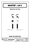
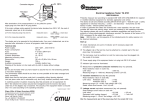
Operating Instructions
Compact Overfill Sensor, Float Type MAXIMAT
VK C...
with integrated mesuring Transducer, DIBT Approval Z-65.11-355
:
Technical Data
Supply power
24 V DC ± 10%
With current limiting or 250 mA fuse recommended
Connected load
Approx. 3 W
Ambient temperature
°
-20 to +60 C
Container pressure
Atmospheric (0.8 to 1.1 bar)
Terminal housing
IP 65
Terminals
Screw terminals: IP 20
Max. wire cross-section: 2.5 mm²
Outputs
Binary output: +DO/-DO max. 20 mA / 24 V +AO / -AO
0 to 20 mA
Output for MAXIMAT SHR C... measuring transducer
DIP Switch
Operating Mode
DIP1
DIP2
DIP3
DIP4
Binary output
ON
ON
ON
OFF
Current output/PLC OFF
OFF
OFF
OFF
MAXIMAT SHR C
OFF * OFF * OFF * OFF *
* Default setting
Note:
Be sure to examine the DIP switch settings before
switching supply power on!
Indicators
Green LED on the connector PCB:
•
Run = LED illuminated
•
Alarm / error = LED off
Safety Precautions
•
•
•
•
Installation, initial start-up and maintenance may only be
performed by trained personnel! All applicable European and
national regulations regarding installation of electrical
equipment must be adhered to.
The device may only be connected to supply power which
complies with the specifications included in the technical data
and on the serial plate!
The device must be disconnected from all sources of power
during installation and maintenance work!
The device may only be operated under the conditions
specified in the operating instructions!
Functions Description
The MAXIMAT VK C... compact overfill sensor is used as a filllevel limit switch for permanently installed containers used for the
storage of non-flammable, water endangering liquids.
It is equipped with three different output circuits:
• A binary output for controlling a coupling relay, or the digital
input of a PLC
• A 0 to 20 mA current output for controlling an analogue input
channel, e.g. a programmed logic controller (PLC)
• Self-monitoring measuring circuit in combination with the
MAXIMAT SHR C... measuring transducer with 2-wire
connection
Measuring circuit for use with SHR C... transducer
Max. cable inductance:
approx. 5 mH
Max. cable capacitance:
approx. 0.5 µF
Measuring circuit cable length
Max. 300 m
Min. wire cross-section: 0.5 mm²
CE mark
In accordance with low-voltage directive (73/23/EWG),
EMC directive (89/336/EWG) and
• EN 50 082-2:1995
• EN 55 011 (class A):1998
DIBT Approval
Approval no. Z-65.11-355 for overfill sensors and leakage
sensors in accordance with WHG §19
Note:
The accompanying “General Building Supervisory Approval
no. Z-65.11-355” is an integral part of the operating
instructions and all stipulations contained therein must be
adhered to!
Note:
Only for liquids with density greater than 0.7g/cm³
The MAXIMAT VK C... compact overfill sensor is used also for oil,
emulsion and other non-conductive liquids.
SU0213.DOC
06/03
© IER Eberhard Henkel GmbH
Sheet 1
Operating Instructions:
MAXIMAT VK C
Compact Overfill Sensor, Float Type
Electrical connection:
MAXIMAT VK C... binary output to coupling relay
MAXIMAT VK C... to MAXIMAT SHR CS measuring
transducer
MAXIMAT VK C... current output to PLC analogue input
MAXIMAT CK C… to MAXIMAT SHR C19 transducer
Adjustment Instructions
The maximum allowable fill-level of any given tank can be
determined, for example, in accordance with TrbF 280 no.
2.2. Triggering level A is then calculated in accordance
with attachment 1, or the approval guidelines for overfill
inhibitors (ZG-ÜS). Dribbling quantities and switching delay
times must be taken into consideration. Switching delay
time can be adjusted at the MAXIMAT SHR C measuring
transducer within a range of 0.3 to 3 seconds.
Installation length L determines the fill-level monitor’s
triggering point.
Dimensions are calculated as follows:
H = tank height
A = triggering level
B = connector
E = immersion depth, table E
S = triggering point
L=H-A+B+E+3
S=L-E–3
SU0213.DOC
06/03
Guide tubes included with MAXIMAT VK.3L and
MAXIMAT VK.4L adjustable level monitors are supplied 50
mm longer than dimension L, so that the fill-level monitor
can be adapted to correspond to triggering level A during
installation. It is thus possible to readjust dimension L.
After the triggering point has been set, the locking screws
are tightened and sealed against tampering. Due to the
fact that this seal is not removed during periodic testing,
dimension L is always fixed, i.e. no readjustment is
necessary
© IER Eberhard Henkel GmbH
Sheet 2