1
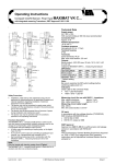
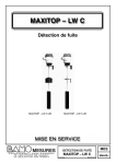
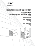
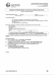
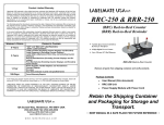
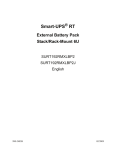
Operating Instructions
MAXIMAT LW CZ ... Compact Leakage Sensor
Technical Data
Supply power
15...26V DC
Power supply with current limiting or 250 mA fuse
recommended
Connected load
Approx. 3 W
Ambient temperature
-20 to +60° C
Container pressure
Atmospheric (0.8 to 1.1 bar)
Outputs
−
Binary output: +DO / -DO max. 30 mA at 24 V DC
−
Current output: +AO / -AO, 0 to 20 mA
−
Output for MAXIMAT SHR C... measuring
transducer
MAXIMAT LW CZ0
MAXIMAT LW CZD
MAXIMAT LW CZK
Safety Precautions
• Installation, initial start-up and maintenance may only
•
•
•
be performed by trained personnel! All applicable
European and national regulations regarding
installation of electrical equipment must be adhered
to.
The device may only be connected to supply power
which complies with the specifications included in the
technical data and on the serial plate!
The device must be disconnected from all sources of
power during installation and maintenance work!
The device may only be operated under the
conditions specified in the operating instructions!
Functions Description
The MAXIMAT LW CZ ... compact leakage sensor is
used as a leakage monitoring device for permanently
installed containers used for the storage of nonflammable, water endangering liquids.
It is equipped with three different output circuits:
• A binary output for controlling a coupling relay or the
digital input at a PLC
• A 0 to 20 mA current output for controlling an
analogue input channel, e.g. a programmed logic
controller (PLC)
• Self-monitoring measuring circuit in combination with
the MAXIMAT SHR C... measuring transducer with 2wire connection
Applications:
Stored liquids may not tend to precipitate insulating or
conductive sediments.
SU0173a.DOC 02/02
© IER Eberhard Henkel GmbH
MAXIMAT LW CZD and ..K
Terminals
Screw terminals, IP 20
Max. wire cross-section: 2.5 mm²
Terminal housing
IP 65
DIP Switch
Operating Mode
DIP1
DIP2
DIP3
DIP4
Binary output
ON
ON
ON
OFF
Current output
OFF
OFF
OFF
OFF
MAXIMAT SHR C
OFF * OFF * OFF * OFF *
* Default setting
Note:
Be sure to examine the DIP switch settings before
switching supply power on!!!
Indicators
Green LED on the connector PCB:
•
Run = LED illuminated
•
Alarm / error = LED off
Measuring circuit for use with SHR C... measuring
transducer
Max. cable inductance:
approx. 5 mH
Max. cable capacitance:
approx. 0.5 μF
Measuring circuit cable length
Max. 300 m
Min. wire cross-section: 0.5 mm²
CE mark
In accordance with low-voltage directive (73/23/EWG),
EMC directive (89/336/EWG) and
• EN 50 082-2:1995
• EN 55 011 (class A):1998
DIBT Approval
Approval no. Z-65.40-316 for overfill inhibitors and
leakage sensors in accordance with WHG §19
Note:
The accompanying “General Building Supervisory
Approval no. Z-65.40-316” is an integral part of the
operating instructions and all stipulations contained
therein must be adhered to!
Page 1
Operating Instructions:
MAXIMAT LW CZ ... Compact Leakage Sensor
Mechanical Installation of the Leakage Sensor
The leakage sensor’s probe is suspended such that it hangs into the catch basin of the storage tank to be monitored. The probe
may make contact with the outside wall of the catch basin, or may stand on its floor. The cable must be secured such that the
probe is always positioned vertically. The connector cable between the probe and the measuring transducer is pulled through
the Pg fitting mounted to the bracket or the cap until the portion of the cable inside the catch basin holds the probe in the vertical
position. When installed in a free-hanging fashion, it must be assured that the connector cable is only pulled far enough through
the adjustor fitting to allow for a maximum clearance of 45 mm between the probe and the catch basin floor, so that the leakage
alarm is triggered at a maximum fill-level of 50 mm.
If the MAXIMAT LW CZ0 variant is used, other suitable mounting components must be utilised in an appropriate fashion.
Adjustment Notes
Installation Example:
Storage Tank Leakage Sensor
The leakage probes are installed inside catch basins. If the bottom of the probe contacts the floor of the catch basin, the alarm
signal is triggered when the liquid reaches a fill-level of approximately 5 mm. For applications involving storage tank catch
basins, the probe must be installed such that the alarm signal is triggered at a fill-level of 50 mm or less.
SU0173a.DOC 02/02
© IER Eberhard Henkel GmbH
Page 2
Operating Instructions:
MAXIMAT LW CZ ... Compact Leakage Sensor
Periodic Testing
The leakage probe must be tested for correct functioning at reasonable intervals, although not less than once a year. It is the
sole responsibility of the user to select the utilised test type, as well as a testing interval within the prescribed timeframe.
Testing must be performed which substantiates flawless functioning of the leakage sensor, and correct interaction with all other
associated components. This is assured by means of suitable simulation of a leak, or the physically measured effect which
causes triggering of the alarm signal. If correct functioning of the leakage sensor can be established by other means (exclusion
of function impairing errors), testing can be executed by simulating the appropriate output signal. Further details concerning test
methods are included, for example, in directive VDI / VDE 2180, page 4.
Leakage Sensor Materials
In the event of a tank leak, the leakage sensor (probe and probe tube) comes into contact with the stored liquid, or vapours and
condensate resulting therefrom. For this reason, leakage sensor materials must be selected which are adequately resistant to
the liquid to be monitored.
Component
Measuring probe
Probe tube
Cap, 63 mm dia. ( ... CZD)
Bracket
Pg fitting
Press-fit seal at Pg fitting
Cable from probe to
measuring transducer
SU0173a.DOC 02/02
Material
Glass carbon
Plastic (polyethylene, PE)
PVC (polyvinyl chloride)
PVC (polyvinyl chloride)
PA (polyamide)
NBR (perbunan)
PVC control cable
© IER Eberhard Henkel GmbH
Page 3
Operating Instructions:
MAXIMAT LW CZ ... Compact Leakage Sensor
MAXIMAT LW CZ... binary output to coupling relay or PLC
MAXIMAT LW CN - SDR...
binary output to coupling relay or PLC
MAXIMAT LW CZ current output to PLC analogue input
SU0173a.DOC 02/02
© IER Eberhard Henkel GmbH
Page 4
Operating Instructions:
MAXIMAT LW CZ ... Compact Leakage Sensor
MAXIMAT LW CZ…
to MAXIMAT SHR CS measuring transducer
MAXIMAT LW CN - SDR...
to MAXIMAT SHR CS measuring transducer
MAXIMAT LW CZ
to MAXIMAT SHR C19 measuring transducer
SU0173a.DOC 02/02
© IER Eberhard Henkel GmbH
Page 5
Operating Instructions:
MAXIMAT LW CZ ... Compact Leakage Sensor
MAXIMAT LW CZ0..
binary output to coupling relay or PLC
MAXIMAT LW CZ0.
current output to PLC analogue input
Attention!
Connect unused
conductors to free
terminals or insulkated
individually!
MAXIMAT LW CZ0.
to MAXIMAT SHR CS measuring transducer
SU0173a.DOC 02/02
MAXIMAT LW CZ0
cable conductor assignments
© IER Eberhard Henkel GmbH
Page 6