1
Page /4
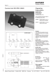
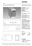
Control Unit SG-RSV 239
IMPORTANT NOTES!
Please read!
To ensure correct and safe operation
of the unit, it must be properly transported and stored, properly installed
and commissioned, and operated in
accordance with its intended use.
Only persons familiar with the installation, commissioning and operation,
and with the corresponding qualifications to prove their skills, may work on
the units.
They must observe the contents of
these instructions, the information
given on the type plate of the unit and
the relevant safety regulations for the
installation and operation of electrical
systems.
This unit is designed in accordance with
EN 50155 and EN 50121-3-2 and left
the factory in a perfectly safe condition.
To maintain this condition, you must
observe the safety regulations marked
WARNING! in these operating instructions. Failure to observe the safety
regulations can lead to death, injury to
personnel, or damage to the unit and
other systems and equipment.
Should the information given in these
operating instructions be inadequate
in any way, please contact your local
technical centre, subsidiary or representative. When using the device
outside the European Union, you must
observe the relevant regulations valid
for the country of use.
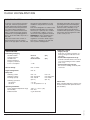
Important notes:
Technical Data
- Supply voltage
must be in accordance with the connecting voltage Us indicated on the
type plate.
- Permissible temperature range
maintain sufficient distance from heat
sources if installing in switch cabinet
(min. 2 cm).
- Fusing of the relay contacts
due to risk of welding, externally with
1.0 A inert.
Connecting Voltage US
DC 24 V
-30% to +30%
DC50 to 150 V
<2W
SG-RSV 239/24
Voltage tolerance
SG-RSV 239
Nominal frequency
Frequency tolerance
Power consumption
Sensor Voltage
max. 12 V DC
Signal Voltage State
max. Us
(S2)
(S2)
Relay Data
Switching current
max. 1 A
max. 1 A
Switching voltagemax. AC 250 V
max. DC 150 V
Breaking capacity
max. 250 W
max. 30 W
(AC 12)
(DC 12)
Switching operations
mechanical
> 2× 10⁷
electrical
> 1× 10⁵ (250 AC V / 1 A)
Operating Conditions
Mayser Polymer Electric
-40 °C to +70 °C (T3)
max. 95%
5 g in all 3 levels
Postfach 30 48
89020 Ulm
Germany
Tel. +49 731 2061-0
Fax +49 731 2061-222
130707 v1.2
Perm. ambient temperature range
Rel. humidity
Endurance limit
Please note:
When switching inductive loads the user
must be fitted out with spark absorbers
(RC-modules).