1
8
1 Single-Screw Extrusion: Introduction and Troubleshooting
much smaller channel depth than the feed section. The ratio of the channel depth
in the feed section to the channel depth in the metering section is often referred to
as the compression ratio of the screw.
1.3.1 Screw Geometric Quantitative Characteristics
The book Engineering Principles of Plasticating Extrusion by Tadmor and Klein [4]
has been used extensively in gaining an understanding of the fundamentals of
extrusion processes. The following section endeavors to maintain the quality of the
development of the screw geometry section of this classic text. Understanding the
relationships between the screw geometry and the symbolic and mathematical
representation of a screw is a critical beginning for understanding the rate, pressure, and temperature calculations. These functions related to the performance of
single-screw extruders are developed later in this book and require an understanding of the screw geometry.
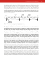
The geometry of a double-flighted screw and its nomenclature are presented in
Fig. 1.4 using the classical description from Tadmor and Klein [4]. The nomenclature has been maintained to provide consistency with the classical literature and
to provide some generality in the development of the symbols and equations that
are used in extruder analysis.
Several of the screw geometric parameters are easily obtained by observation
and measurement, including the number of flight starts, inside barrel diameter,
channel depth, lead length, flight width, and flight clearance. The number of
flight starts, p, for the geometry in Fig. 1.4 is two. The inner diameter of the barrel is represented by Db, and the local distance from the screw root to the barrel
θ (r)
H
barrel
y
Db
Dc
screw
W(r)
x
e
z
λ
B
b
L
Figure 1.4 A schematic of a double-flighted screw geometry