1
Betriebsanleitung
Triebwagen Talent BR 643 – Spur H0
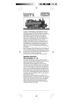
643 sind bereits für die Deutsche Bahn AG erfolgreich im Einsatz.
Der 643 wird von zwei Dieselmotoren mit einer Leistung von je
315 kW angetrieben und verfügt über 137 Sitzplätze.
Der Triebwagen Talent wurde von Bombardier Transportation,
früher Talbot, in Aachen entwickelt. Mit „Talent“ wird eine ganze
Fahrzeugfamilie bezeichnet.
Der dieselelektrische Triebwagen 644 und der dieselmechanische
Operating Instructions
Motor Coach Talent BR 643 – H0
mechanical 643 are already used successfully by the Deutsche
Bahn AG. The 643 is driven by two diesel motors with an output of
315 kW each and has seats for 137 passengers.
The Talent motor coach was developed by Bombadier
Transportation, formerly Talbot, in Aachen. “Talent” is the vehicle
family name. The diesel-electric motor coach 644 and the diesel-
Nicht bestimmt für Kinder unter 3 Jahren. Verschluckbare Kleinteile. Betriebsanleitung aufbewahren!
Not recommended for children under 3 years of age. Small parts may be swallowed. Retain the operating instructions!
Zum Betrieb des vorliegenden Produkts darf als Spannungsquelle nur ein nach VDE 0551/EN 60742 gefertigter Spielzeug-Transformator verwendet werden.
Only a toy transformer produced compliant with VDE 0551/EN 60742 may be used as a voltage source to operate this product.
Dieses Produkt entspricht den grundlegenden Sicherheits- und Gesundheitsanforderungen der Europäischen Richtlinie für Spielzeuge
(88/378/EWG) unter Beachtung der Europäischen Sicherheitsnorm EN 71.
This product conforms to the fundamental health and safety requirements of the European Directive for Toys (88/378/EEC) with due
regard to the European Safety Standard EN 71.
Elektro- und Elektronikaltgeräte dürfen nicht in den Hausmüll gelangen. Sie müssen entsprechend der jeweils gültigen Länderrichtlinien fachgerecht entsorgt werden.
Electrical equipment may not reach to domestic waste. According to the current terms of the country reference the electrical
eqipment must professional disposed.
1
Inhaltsverzeichnis
Contents
Benennung
Seite
Allgemeine Montage- und Sicherheitshinweise
Allgemeine Hinweise ....................................................................... 2
• Diese Bedienungsanleitung beschreibt sämtliche Arbeitsvorgänge die zur Wartung und Instandhaltung notwendig sind.
Bitte lesen Sie diese Bedienungsanleitung bevor Sie mit den
Arbeiten beginnen.
Entnahme der Lok aus der Verpackung ......................................... 3
Ölen ................................................................................................. 3
• Bei unsachgemäßem Umgang mit elektrischen Bauteile können
diese zerstört werden. Für entsprechende Arbeiten
(z.B. Platinenwechsel) können Sie sich an Ihren Fachhändler
oder den Hersteller wenden.
Zusatzbauteile montieren ................................................................ 3
Ümrüsten und Umprogrammieren auf Digitalbetrieb ...................... 4
• Bei den folgenden Wartungsarbeiten ist die jeweilige Demontage
beschrieben, der Zusammenbau ist in umgekehrter Reihenfolge
auszuführen.
Wartungsarbeiten
• 1. Gehäuse demontieren .......................................................... 6
• 2. Motor tauschen .................................................................... 6
• 3. Platine tauschen .................................................................. 6
• 4. Digital-Decoder tauschen .................................................... 6
• 5. Glühbirnen tauschen ............................................................ 6
• 6. Wartungsarbeiten an Radsätze, Getriebe
und Haftreifen erneuern ...................................................... 6
• 7. Schleiferwechsel bei Wechselstrom-Ausführung ................ 6
• Die folgenden Wartungsarbeiten sind bei Gleich- und Wechselstrom-Ausführungen fast identisch. Im Ausnahmefall wird im
entsprechenden Textabschnitt Bezug genommen.
• Achten Sie beim Zerlegen der Lokomotive auf die Einbaulage
der entsprechenden Bauteile. Wird ein Bauteil falsch eingebaut
kann dieses zerstört werden oder es kommt zu Funktionsstörungen im Betrieb.
• Beim Betrieb auf märklin C-Gleis beachten Sie bitte die
Hinweise auf Seite 11.
Ersatzteilliste ................................................................. 8, 9, 10, 11
• Jegliche Kabel oder Verbindungsdrähte die in diesem Produkt
verbaut sind dürfen nicht in eine Netzsteckdose eingeführt werden.
Lebensgefahr!
Bestellbeispiel ............................................................................... 11
Hinweis zum Betrieb auf märklin C-Gleis ..................................... 13
General assembly and safety information
Description
Page
• These operating instructions describe all work steps necessary
for maintenance and repair. Please read these operating
instructions carefully before you start with your work.
General information ........................................................................ 2
Removing the locomotive from the packaging .............................. 3
Lubrication ...................................................................................... 3
• In the case of incorrect handling of electrical components, they
may be destroyed. Please ask your specialist dealer to help
with the necessary work (e.g. changing circuit boards).
Fitting additional parts ..................................................................... 3
• In the case of maintenance work, the disassembly is described
below, to re-assemble the tractor reverse the work steps.
• The maintenance work described below is virtually identical for
direct current and alternating current models. If there are any
differences these will be pointed out specifically.
Converting to digital operation ........................................................ 5
Maintenance works
• 1. Dismantling the housing ...................................................... 7
• 2. Replacing the motor ............................................................ 7
• 3. Replacing the circuit board ................................................. 7
• 4. Replacing the digital decoder .............................................. 7
• 5. Replacing light bulbs ............................................................ 7
• 6. Maintenance work on the gear, replacing wheelset
and adhesion rings ............................................................... 7
• 7. Replacing the trailer in the AC version ................................ 7
• When dismantling the engine make a note of the mounted position
of the individual parts. An incorrectly mounted part
can be destroyed or operation can be disrupted.
• If Talent Connex is used with märklin C-Rail, please pay attention
to the informations on page 11.
• All cables and connection wires installed in this product may not
be inserted in a mains socket. Danger!
Spare parts list .............................................................. 8, 9, 10, 12
Order example ............................................................................... 12
Information for use with märklin C-Rail ........................................ 13
2
Entnahme der Lok aus der Verpackung
Ölen
Verpackung öffnen, Styropor mit Lokomotive herausziehen.
Lokomotive über die Öffnungen an der Rückseite vorsichtig
aus der Verpackung drücken.
Der Motor und die Lagerstellen der Radsätze können an den gekennzeichneten Punkten sparsam mit Öl der Modellbaubranche
geölt werden. Zum Ölen des Motors ist das Gehäuse und die
Motorabdeckung abzunehmen, siehe Seite 5 Punkt 2. und 3.
Removing the locomotive from the packaging
Lubricating
Open packaging, pull out polystyrene with locomotive.
Press locomotive out of the packaging through the opening
on the bottom.
The motor and the wheelset bearings may be sparingly lubricated
at the marked places with oil used for model making purposes.
In order to lubricate the motor, remove the housing and the motor
holding plate, compare page 5, item 2 and 3.
Motor
Motor
Räder
Wheels
If two of these motor coaches are used in double traction,
the enclosed aprons (1) have to be mounted.
Unscrew the fastening screws (3), take the apron off and remove
the coupling imitation (4). Mount the coupling imitation to the new
apron and fasten to the locomotive. The coupling (2) is suspended
in the hook of he corresponding transmission housing. The
locomotives are now connected together and can be used in
double traction.
Zusatzbauteile montieren
In der Verpackung sind zusätzliche Bauteile lose beigelegt.
1 = 1 x Schürze zum kuppeln
2 = 1 x Kupplung für Doppeltraktion
3 = 4 x Befestigungsschraube
4 = 2 x Kupplungsimitation
Werden zwei dieser Triebwagen in Doppeltraktion gefahren
müssen die beigelegten Schürzen (1) montiert werden.
Befestigungsschrauben (3) herausdrehen, Schürze nach unten
abnehmen und Kupplungsimitation (4) entfernen. Kupplungsimitation an neue Schürze montieren und diese am Triebwagen
befestigen. Die Kupplung (2) wird in den Haken des jeweiligen
Getriebegehäuses eingehängt. Jetzt sind die Triebwagen miteinander verbunden und können in Doppeltraktion gefahren werden.
Fitting additional parts
Accessory parts have been loosely enclosed in the packaging.
1 = 1 x coupling aprons
2 = 1 x coupling for double traction
3 = 4 x fastening screws
4 = 2 x coupling imitation
04
01
03
02
01
3
Umrüsten auf Digitalbetrieb
Umrüsten auf Digitalbetrieb
Wechselstrom-Ausführung
Gleichstrom Ausführung
Betriebsverhalten der Lok bei Analog/Digitalbetrieb
Grafik zu den nachfolgenden Arbeitsschritten siehe Seite 6.
Gehäuse des Triebwagens (mit Haftreifen) demontieren, siehe
Punkt 1. Blindstecker (6) abziehen und Digital-Decoder (7)
einstecken.
Den richtigen Einbau des Digitaldecoders und dessen
Einsteckrichtung entnehmen Sie der Einbauvorschrift des
Decoderherstellers.
Nach Einstecken des Digitaldecoders ist die Funktion des Lichtes
zu prüfen. Wenn keine Lichtfunktion – Stecker um 180° drehen
und einstecken.
Wichtiger Hinweis:
Bitte beachten Sie das Betriebsverhalten der Lok je nach
Gleich-/Wechselstrom und Digital/Analogbetrieb.
Dies wird im anschließenden Text erläutert.
Analogbetrieb
Sobald der in Fahrtrichtung vorne liegende Schleifer einen spannungslosen Abschnitt erreicht, hält der Decoder den Motor an.
Digitalbetrieb
Sobald der in Fahrtrichtung vorne liegende Schleifer einen spannungslosen Abschnitt erreicht, bremst der Decoder mit der
eingestellten Bremsverzögerung ab.
Wechselstrom-Ausführung
Lokomotiven in Wechselstrom-Ausführung AC werden serienmäßig
mit Premium-Digitaldecoder (7) ausgeliefert. Der Decoder erkennt
die Betriebsart (analog/digital) selbstständig. Soll der Decoder
umprogramiert werden, liegt die Einbau- und Betriebsanleitung
Premium-Digitaldecoder bei.
Der Decoder ist Werkseitig auf Adresse 03 eingestellt.
Gleichstrom-Ausführung
Betriebsverhalten der Lok bei Analog/Digitalbetrieb
Analogbetrieb
Die Stromabnahme erfolgt von 3 Drehgestellen. Somit kann es
sein, dass das Fahrzeug über eine Stoppstelle hinausfährt. Wenn
dies nicht gewünscht wird, muss das Kabel (siehe Abb. rechts)
durchtrennt werden. Damit muss aber in Kauf genommen werden,
dass in einer Fahrtrichtung der Zug an Weichenstraßen stoppen
kann.
Digitalbetrieb - nach Umrüstung
Die Platine ist mit einer Schnittstelle versehen. Diese Schnitt-stelle
besitzt einen 9. Pin. Dieser Pin soll eine Schleiferumschal-tung
realisieren. Da es im Moment noch keine Gleichstromdecoder auf
dem Markt gibt, die dies können, haben wir Pin 9 mit Pin 8
gebrückt. Sie können daher jeden handelsüblichen Gleichstromdecoder einbauen. Sollte es in Zukunft einen Decoder mit
Schleiferumschaltung geben, müssen Sie nur noch das Kabel
(siehe Abb. rechts) durchtrennen. Damit ist die Schleiferumschaltung auch in Gleichstrom realisiert.
4
Converting to digital operation
Converting to digital operation
AC version
DC version
Operating behaviour of the locomotive
in analog/digital operation
Remove middle coach, pull off dummy connector (5) and insert
digital decoder (see page 6).
Please consult the installation instructions issued by the
decoder manufacturer for correct installation of the digital
decoder and its insert direction.
After inserting the digital decoder, check that the light functions. If
the light does not work, turn the connector through 180°.
Important note:
Please note the operating behaviour of the locomotive depending
on DC/AC current and digital/analog operation.
This is explained below.
Analog operation
As soon as the leading trailer reaches an idle section, the decoder
stops the engine.
AC version
The premium digital decoder (04) is standard for the alternating
current (AC) locomotives models. The decoder independently
identifies the operation type (analog/digital). Please refer to the
enclosed installation and operation instructions “Premium Digital
Decoder” in the event that the decoder needs to be
reprogrammed.
Digital operation
As soon as the leading trailer reaches an idle section, the decoder
brakes with the set braking delay.
The decoder is set to address 03 in the factory.
DC version
Operating behaviour of the locomotive
in analog/digital operation
Analog operation
The current is picked up by 3 bogies. This means that it is possible
for the vehicle to drive beyond a stopping point. If this is not
wanted, the cable has to be cut (see fig.). But you must then
expect the train to stop at the points in one direction.
Digital operation - after converting
The circuit board has an interface with a 9th pin. This pin is
responsible for trailer change-over. At the moment there are no DC
decoders on the market so that we have bridged pin 9 with pin 8.
You can therefore use any commercially available DC decoder. If in
future decoders with trailer change-over should become available,
you only have to cut the cable (see fig.).
This then ensures that trailer change-over is also possible
in the DC version.
5
Wartungsarbeiten
Wagen vorn mit Antriebseinheit /Triebwagen), zu erkennen
an den Haftreifen.
Wartungsarbeiten
1. Gehäuse demontieren
Gehäuse vorn (Triebwagen, zu erkennen an den Haftreifen) und
Gehäuse hinten demontieren:
• Schraube (1) an der Gehäuseunterseite herausdrehen, Gehäuse
(2) leicht spreizen und nach oben abnehmen.
Gehäusemittelteil demontieren (ohne Abbildung):
• Das Gehäuse des Mittelteils leicht spreizen und nach oben
abnehmen (keine Befestigungsschrauben).
02
2. Motor tauschen
Gehäuse des Triebwagens (mit Haftreifen) demontieren,
siehe Punkt 1. Befestigungsschrauben (3, 8) herausdrehen und
Motorabdeckung (4) nach oben abnehmen. Gummilager des
Motors mit Schraubendreher nach oben drücken, Motor (5) nach
oben entnehmen. Kabel am Motor ablöten.
Achtung: Bei Ausbau auf Einbaulage achten – sonst falsche
Fahrtrichtung.
04
08
07
10
AC
3. Platine tauschen
Gehäuse des Triebwagens (mit Haftreifen) demontieren,
siehe Punkt 1. Blindstecker (6) bei DC-Ausführung oder DigitalDecoder (7) bei AC-Ausführung abziehen. Befestigungsschraube
(8) herausdrehen, Platine (9) nach oben abnehmen. Sämtliche
Kabel an der Platine ablöten, bitte kennzeichnen Sie sich wo die
einzelnen Kabel angelötet waren.
06
DC
10
09
AC
DC
4. Digital-Decoder tauschen
Gehäuse des Triebwagens (mit Haftreifen) demontieren,
siehe Punkt 1. Digital-Decoder (7) abziehen und neuen DigitalDecoder einstecken.
05
5. Glühbirnen tauschen
Entsprechendes Gehäuse abnehmen, siehe Punkt 1.
Motorabdeckung entfernen, siehe Punkt 2.
Kabel an Glühbirne (10) ablöten und Glühbirne erneuern.
11
01
6. Wartungsarbeiten am Getriebe und an den Radsätzen
sowie Haftreifen erneuern
Getriebe:
Gehäuse des Triebwagens (mit Haftreifen) demontieren,
siehe Punkt 1. Motorabdeckung entfernen, siehe Punkt 2.
Triebwagen auf einen Tisch stellen, Befestigungsschraube (11) des
Drehgestells herausdrehen und Drehgestell (12) nach unten
entnehmen. Jetzt ist das Zahnrad (13) frei zugänglich.
03
13
12
Radsätze, Haftreifen und weitere Zahnräder:
Achtung: Triebwagen (mit Haftreifen) oder demontiertes
Drehgestell umdrehen, Räder und Getriebeabdeckung
müssen nach oben zeigen.
Befestigungsschraube (14 bei DC/19 bei AC) der Getriebeabdeckung herausdrehen, Getriebeabdeckung (15) ausclipsen,
Radsätze (16) entnehmen. Jetzt können auch die Haftreifen (17)
erneuert und weitere Zahnräder (18) entnommen werden.
18
17
16
Clip
15
DC
AC
15
Clip
7. Schleifer tauschen bei Wechselstrom-Ausführung
Befestigungsschraube (19) des Schleifers (20) herausdrehen,
Schleifer abnehmen.
14
20
19
6
Maintenance Work
Front coach with drive unit (motor coach), can be recognised
with the adhesion rings.
Maintenance works
1. Dismantling the housing
Dismantle housing at the front (motor coach, recognizable by the
traction tyres) and housing at the back:
• Unscrew the screw (1) on the housing lower part, gently spread
the housing (2) and take out upwards.
Dismantle housing middle section (without illustration).
• Gently spread the housing of the middle section and take out
upwards (no fastening screws).
02
2. Replacing the motor
Dismantle the motor coach housing (with traction tyres), see point
1. Unscrew the fastening screws (3, 8) and take motor cover (4)
off upwards. Push rubber bearing of the motor upwards with a
screwdriver, take motor (5) off upwards. Unsolder the cable at the
motor.
Caution: Pay attention to the installation position when removing
the motor, otherwise wrong direction of travel.
04
08
07
10
AC
3. Replacing the circuit board
Remove housing of locomotive with adhesion rings, see point 1.
Pull off the dummy connector (6) in the DC version or the digital
decoder (7) in the AC version. Unscrew the fastening screw (8)
and take the circuit board (9) off upwards. Unsolder all cables on
the circuit board, please mark where the individual cables were
soldered on.
10
4. Replacing the digital decoder
Remove housing of locomotive with adhesion rings, see point 1.
Pull the digital decoder (7) off and insert new digital decoder.
05
06
DC
09
AC
DC
5. Replacing light bulbs
Remove corresponding housing, see point 1.
Remove motor cover, see point 2.
Unsolder cables on the light bulb (10) and replace the light bulb.
11
01
6. Maintenance work on the gear and at the wheelsets
and replacing traction tyres
Transmission:
Remove housing of locomotive with adhesion rings, see point 1.
Remove motor cover, see point 2. Place locomotive on a table,
unscrew the fastening screw (11) of the bogie and take bogie (12)
out downwards. The gear wheel (13) is now freely accessible.
03
13
Wheelsets, adhesion rings and other gear wheels:
Caution: Turn over motor coach (with traction tyres) or
dismantled bogie; wheels and transmission cover must
point upwards.
Unscrew the fastening screw (14 DC/19 AC) of the gear cover,
unclip the gear cover (15), remove wheelsets (16). You can now
replace the adhesion rings (17) and other gear wheels (18).
12
18
17
16
7. Replacing the trailer in the AC version
Unscrew the fastening screw (19) of the trailer (20).
Clip
15
DC
AC
15
Clip
14
20
19
7
Ersatzteilliste Triebwagen Talent BR 643
Spare Parts List Motor Coach Talent BR 643
Gleichstrom / Wechselstrom
DC current / AC current
71
72
Wagen vorn mit Antriebseinheit
(Antriebswagen), zu erkennen an den
Haftreifen.
Ersatzteilliste siehe Seite 11.
Front coach with drive unit (motor
coach), can be recognised
with the adhesion rings.
Spare parts list see page 12.
01
62
60
59
61
69
63
68
70
56
36
58
83
55
77
DC
52
82
53
54
AC
73
50
46
51
47
54
49
45
81
43
44
42
41
48
04
78
32
13
39
40
31
19
22
30
24
38
37
29
23
18
15
14
21
20
08
20
08
DC
AC
25
28
26
27
10
8
Ersatzteilliste Triebwagen Talent BR 643
Spare Parts List Motor Coach Talent BR 643
Gleichstrom / Wechselstrom
DC current / AC current
Wagen mitte
Ersatzteilliste siehe Seite 11.
Middle coach
Spare parts list see page 12.
65
02
64
57
87
80
79
33
84
79
57
07
34
11
05
13
31
87
13 30
32
31
33
35
84
30
07
34
11
06
32
06
06
85
12
86
06
85
12
9
Ersatzteilliste Triebwagen Talent BR 643
Spare Parts List Motor Coach Talent BR 643
Gleichstrom / Wechselstrom
DC current / AC current
71
Wagen hinten ohne Antriebseinheit und ohne Haftreifen.
Ersatzteilliste siehe Seite 11.
58
69
70
72
68
66
03
Rear coach without drive unit
and adhesion rings.
Spare parts list see page 12.
59
67
52
56
53
54
75
50
51
49
44
76
43
74
42
54
19
78
22
81
37
38
04
18
17
29
13
40
39
21
32
31
16
30
09
09
25
AC
DC
26
27
28
10
10
Ersatzteilliste Triebwagen Talent BR 643
Pos.
Bestell Nr.
Benennung
Pos.
Bestell Nr.
Benennung
01
02
03
04
05
06
10
11
12
13
14
15
16
17
18
19
20
21
22
23
24
25
44006.50.01
44006.50.02
44006.50.03
0730.50.04
0730.50.05
0710.50.06*
0711.50.06**
0710.50.07
0710.50.08*
0711.50.08**
0710.50.09*
0711.50.09**
0711.50.10**
0710.50.11
0710.50.12
0710.50.13
0710.50.14
0710.50.15
0710.50.16
0710.50.17
0710.50.18
0710.50.19
0710.50.20
0710.50.21
0710.50.22
0710.50.23
0710.50.24
0710.50.25
54
55
56
57
58
59
60
61
62
63
64
65
66
67
68
69
70
71
72
73
0710.50.54
0730.50.55
0710.50.56
0710.50.57
0716.50.58
0716.50.59
0716.50.60
0716.50.61
0716.50.62
0716.50.63
0730.50.64
0730.50.65
0716.50.66
0716.50.67
0716.50.68
0716.50.69
0710.50.70
0716.50.71
0716.50.72
0730.50.73
26
0710.50.26
74
75
76
77
78
79
80
81
82
27
28
29
30
31
32
33
34
35
36
37
38
39
40
41
42
43
44
45
46
47
48
49
50
51
52
53
0710.50.27
2225**
0710.50.29
0710.50.30
0710.50.31
0710.50.32
0710.50.33
0710.50.34
0730.50.35
9750**
0710.50.37
0710.50.38
0710.50.39
0710.50.40
0710.50.41
0710.50.42
0710.50.43
0710.50.44
0710.50.45
0710.50.46
0710.50.47
0710.50.48
0710.50.49
0710.50.50
0710.50.51
0710.50.52
0710.50.53
Gehäuse A
Gehäuse B
Gehäuse C
Chassis A und C
Chassis B
Radsatz Jacobs DC
Radsatz Jacobs AC
Drehgestellrahmen links
Radsatz DC mit Haftreifennut
Radsatz AC mit Haftreifennut
Radsatz DC ohne Haftreifennut
Radsatz AC ohne Haftreifennut
Schraube für Schleifer
Drehgestellrahmen rechts
Zentrale Drehgestellabdeckung
Feder
Drehgestellrahmen 1
Drehgestellrahmen 2
Drehgestellrahmen 3
Drehgestellrahmen 4
Schraube für Schürze
Signalhorn
Haftreifen
Getriebegehäuse
Schraube für Inneneinrichtung
Zwischenrad
Schneckenrad
Getriebeabdeckung mit
Radschleifer
Getriebeabdeckung ohne
Radschleifer
Schraube
Wechselstromschleifer
Schraube für Gehäuse
Schraube für Abdeckung
Abdeckung
Kinematic
Kupplungsstück
Bodenplatte Jacobsdrehgestell
Gewicht
Premium-Digitaldecoder
Kupplungsimitation
Schürze standard
Schürze zum Kuppeln
Kupplung für Doppeltraktion
Schnecke
Halter für Schnecke
Schraube klein
Schraube groß
Kardanwelle
Motor
Motorlager
Motorhalter
Lichtleiter rot
Lichtleiter weiß
Lichttrennung
Lichtleiter weiß oben
Kabinenwand
0730.50.74
0710.50.75
0710.50.76
0710.50.77
0710.50.78
0710.50.79
0730.50.80
0730.50.81
0710.50.82*
0733.50.82**
0530.99.34*
0710.50.84
0710.50.85
0730.50.86
0710.50.87
Glübirne
Kabelkanal
Stecker
Dose
Fenster Führerstand links
Fenster Führerstand rechts
Fenster 1
Fenster 2
Fenster 3
Fenster 4
Fenster 5
Fenster 6
Fenster 7
Fenster 8
Frontfenster
Fenstereinsatz
Scheibenwischer
Auspuff
Lufteinlass
Inneneinrichtung mit Motorabdeckung
Inneneinrichtung
WC-Wand
Schraube
Schraube für Platine
Antriebsimitation
Schraube
Abdeckung 1 (groß)
Abdeckung 2 (klein)
Platine DC
Platine AC
Blindstecker
Luftfeder
Schraube
Abdeckung 3
Faltenbalk
07
08
09
83
84
85
86
87
Wichtiger Hinweis!
Bei der Bestellung von Ersatzteilen muss die Bestell-Nr. und die
Benennung angegeben werden.
Ist dies nicht der Fall, kann die Bestellung nicht bearbeitet werden.
Bestellbeispiel:
Position (46), Motor = 0710.50.46, Motor
* Bauteil wird nur bei Gleichstrom-Ausführung verwendet
** Bauteil wird nur bei Wechselstrom-Ausführung verwendet
11
Spare Parts List Motor Coach Talent BR 643
Pos.
Order no.
Description
Pos.
Order no.
Description
01
02
03
04
05
06
44006.50.01
44006.50.02
44006.50.03
0730.50.04
0730.50.05
0710.50.06*
0711.50.06**
0710.50.07
0710.50.08*
Body A
Body B
Body C
Chassis A and C
Chassis B
Wheelset Jacobs DC
Wheelset Jacobs AC
Bogie frame left
Wheelset DC with preparing for
traction tires
Wheelset AC with preparing for
traction tires
Wheelset DC without preparing
for traction tires
Wheelset AC without preparing
for traction tires
Screw for pick up shoe
Bogie frame right
Central bogie cover
Spring
Bogie frame 1
Bogie frame 2
Bogie frame 3
Bogie frame 4
Screw for pilot
Horn
Traction tire
Gearbox
Screw for motor cover
Idle gear
Worm gear
Gear cover with pick up
Gear cover without pick up
Screw
AC pick up shoe
Screw for body
Screw for holding plate
Holding plate
Kinematic
Coupler hook
Base plate bogie
Weight
Premium digital decoder
Coupler imitation
Pilot standard
Pilot for coupling
Coupler for two trains
Worm
Holder for worm
Screw small
Screw big
Coupler rod
Motor
Motor bearing
Motor support
Light bar red
Light bar white
Light seperator
Light bar white top
Cab wall
54
55
56
57
58
59
60
61
62
63
64
65
66
67
68
69
70
71
72
73
74
75
76
77
78
79
80
81
82
0710.50.54
0730.50.55
0710.50.56
0710.50.57
0716.50.58
0716.50.59
0716.50.60
0716.50.61
0716.50.62
0716.50.63
0730.50.64
0730.50.65
0716.50.66
0716.50.67
0716.50.68
0716.50.69
0710.50.70
0716.50.71
0716.50.72
0730.50.73
0730.50.74
0710.50.75
0710.50.76
0710.50.77
0710.50.78
0710.50.79
0730.50.80
0730.50.81
0710.50.82*
0733.50.82**
0530.99.34*
0710.50.84
0710.50.85
0730.50.86
0710.50.87
Light bulb
Wire holder
Plug
Socket
Window driver cabin left
Window driver cabin right
Window 1
Window 2
Window 3
Window 4
Window 5
Window 6
Window 7
Window 8
Front window
Front window insert
Windshift wiper
Exhaust
Air chanel
Motor cover
Seat plate
Restroom wall
Screw
Screw for PCB
Imitation of motor
Screw
Cover 1 (big)
Cover 2 (small)
PCB DC
PBC AC
Blind plug
Air bellow spring
Screw
Cover 3
Diaframe
07
08
0711.50.08**
09
0710.50.09*
0711.50.09**
10
11
12
13
14
15
16
17
18
19
20
21
22
23
24
25
26
27
28
29
30
31
32
33
34
35
36
37
38
39
40
41
42
43
44
45
46
47
48
49
50
51
52
53
0711.50.10**
0710.50.11
0710.50.12
0710.50.13
0710.50.14
0710.50.15
0710.50.16
0710.50.17
0710.50.18
0710.50.19
0710.50.20
0710.50.21
0710.50.22
0710.50.23
0710.50.24
0710.50.25
0710.50.26
0710.50.27
2225**
0710.50.29
0710.50.30
0710.50.31
0710.50.32
0710.50.33
0710.50.34
0730.50.35
9750**
0710.50.37
0710.50.38
0710.50.39
0710.50.40
0710.50.41
0710.50.42
0710.50.43
0710.50.44
0710.50.45
0710.50.46
0710.50.47
0710.50.48
0710.50.49
0710.50.50
0710.50.51
0710.50.52
0710.50.53
83
84
85
86
87
Important notice!
When ordering spare parts you must always state the order
number and give the description.
If you do not do this, the order cannot be processed.
Order example:
Position (46), motor = 0710.50.46, motor
* Part is only used for the DC version
** Part is only used for the AC version
12
Ergänzender Hinweis
Beim Betrieb des TALENT H0 auf dem neuen märklin C-Gleis kann
das Fahrgestell des Triebwagens an der Weichenlaterne streifen.
Dies kann zur Folge haben, dass der Triebwagen im ungünstigsten
Fall entgleist.
Fig. 1
Fig. 2
Original Befestigung der
Laterne am märklin C-Gleis
Modifizierte Befestigung
der Laterne am märklin CGleis
Fig. 3
Fig. 4
Original Lichtleiter der
Laterne
Modifizierter Lichtleiter der
Laterne
Für eine schnelle und unkomplizierte Lösung sollte die Weichenlaterne folgendermaßen modifiziert werden:
Die Aufnahme für die Laterne (Fig. 1) ist um 1mm zu kürzen.
(Siehe Fig. 2)
Der Lichtleiter (Fig. 3) ist am oberen Ende um 2mm zu kürzen.
(Siehe Fig. 4)
Abschließend möchten wir darauf hinweisen, dass der TALENT
Triebwagen in enger Zusammenarbeit mit Talbot Bombadier in
Aachen, dem Hersteller des Vorbildmodells, entwickelt wurde und
somit dem Original bis ins Detail entspricht. Auch die niedrigen
Fahrgestelle wurden dem Vorbild 1:1 nachgebildet.
Bitte verstehen Sie dies nicht als Entschuldigung für unser Modell
sondern lediglich als Darstellung der Problematik.
Brawa Modellspielwarenfabrik GmbH + Co.
Uferstraße 26-28 · D-73630 Remshalden
Telefon +49 (0)7151 - 97 93 50
Telefax+49 (0)7151 - 7 46 62
http://www.brawa.de
13
44004.50.88 / 07 05 - WAN
märklin ist eingetragenes Warenzeichen der "geb. Märklin & Cie. GmbH Göppingen"