1
Betriebsanleitung
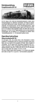
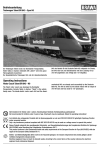
Triebwagen (LVT) VT2.09 der DR
Im Jahre 1969 erhielt die Deutsche Reichsbahn letztmalig eine Lieferung
der erfolgreichen Leichtverbrennungstriebwagen. Da der bisherige Lieferant, der VEB Waggonbau Bautzen als Hersteller nicht mehr zur Verfügung stand, wurden die 73 Triebwagen, zu denen auch 73 Steuerwagen
entstanden, vom VEB Waggonbau Görlitz geliefert. Gegenüber den
Vorgängerserien ergaben sich einige Verbesserungen und Änderungen,
die das Dienstgewicht der Fahrzeuge um 4 t ansteigen ließen. Neben
Bahnbetriebswerken, die schon Erfahrungen im LVT-Einsatz hatten, wurden auch mehrere Dienststellen bedacht, bei denen der LVT-Einsatz völlig neu war.
Operating Instructions
Railcar (LVT) VT2.09 DR
In 1969 the Deutsche Reichsbahn received the last delivery of the
successful light railcars. As the previous supplier, VEB Waggonbau Bautzen, was no longer available as a manufacturer, the 73 railcars, for which
73 control cars were also produced, were supplied by VEB Waggonbau
Görlitz. Compared with previous series, several improvements and changes
were made, which increased the service weight of the vehicles by four
tonnes. In addition to railway depots which already had experience of the
use of LVTs, several divisions were also considered for which the use of
LVTs was completely new.
1
Inhaltsverzeichnis
Contents
Benennung
Seite
Allgemeine Hinweise ........................................................................... 3
Entnahme der Lok aus der Verpackung ................................................ 4
Zusatzbauteile montieren .................................................................... 4
Wartungsarbeiten
• 1. Ölen ............................................................................................. 5
• 2. Umrüsten auf Digitalbetrieb ......................................................... 5
• 3. Gehäuse demontieren ............................................................. 6, 7
• 4. Motor / Platine tauschen .......................................................... 6, 7
• 5. Digitaldecoder tauschen .......................................................... 6, 7
• 6. Haftreifen und Radsätze tauschen ........................................... 6, 7
• 7. Kupplungsnormschacht tauschen ............................................ 6, 7
• 8. Schleifer tauschen bei Wechselstrom-Ausführung AC ............. 6, 7
• 9. Beleuchtungseinrichtung ......................................................... 6, 7
Ersatzteilliste
Gleichstrom- und Wechselstrom-Ausführung ............................. 10 – 12
Bestellbeispiel ................................................................................... 13
Description
Page
General information ............................................................................. 3
Removing the locomotive from the packaging ..................................... 4
Fitting additional parts ......................................................................... 4
Maintenance works
• 1. Lubricating .................................................................................. 5
• 2. Conversion to digital operating .................................................... 5
• 3. Dismantling housing ................................................................ 8, 9
• 4. Exchanging the motor / circuit board ........................................ 8, 9
• 5. Exchanging the digital decoder ............................................... 8, 9
• 6. Exchanging traction tires and wheelsets ................................. 8, 9
• 7. Exchanging coupler pocket ..................................................... 8, 9
• 8. Exchanging the pick up, alternating current AC ....................... 8, 9
• 9. Light fittings ............................................................................ 8, 9
Spare parts list
Direct current and alternating current ........................................ 10 – 12
Order example ................................................................................... 13
2
Arbeiten vor der Inbetriebnahme
Work to be performed before starting up
Allgemeine Montage- und Sicherheitshinweise
• Diese Bedienungsanleitung beschreibt sämtliche Arbeitsvorgänge
die zur Wartung und Instandhaltung notwendig sind.
Bitte lesen Sie diese Bedienungsanleitung bevor Sie mit den
Arbeiten beginnen.
• Bei unsachgemäßem Umgang mit elektrischen Bauteilen können
diese zerstört werden. Für entsprechende Arbeiten (z.B. Platinenwechsel) können Sie sich an Ihren Fachhändler oder den Hersteller
wenden.
• Bei den folgenden Wartungsarbeiten ist die jeweilige Demontage
beschrieben, der Zusammenbau ist in umgekehrter Reihenfolge
auszuführen.
• Die folgenden Wartungsarbeiten sind bei Gleich- und Wechselstrom-Ausführungen fast identisch. Im Ausnahmefall wird im
entsprechenden Textabschnitt Bezug genommen.
• Jegliche Kabel oder Verbindungsdrähte die in diesem Produkt
verbaut sind dürfen nicht in eine Netzsteckdose eingeführt werden.
Lebensgefahr!
General assembly and safety information
• These operating instructions describe all work steps necessary for
maintenance and repair. Please read these operating instructions
carefully before you start with your work.
• In the case of incorrect handling of electrical components, they
may be destroyed. Please ask your specialist dealer to help with
the necessary work (e.g. changing circuit boards).
• In the case of maintenance work, the disassembly is described
below, to re-assemble the tractor reverse the work steps.
• The maintenance work described below is virtually identical for
direct current and alternating current models. If there are any
differences these will be pointed out specifically.
• All cables and connection wires installed in this product may not be
inserted in a mains socket. Danger!
3
Wartungsarbeiten
Maintenance works
Entnahme der Lok aus der Verpackung (Fig. 1)
Verpackung öffnen, Styropor mit Lokomotive herausziehen.
Lokomotive über 2 Öffnungen an der Unterseite aus der Verpackung
drücken.
Removing the locomotive from the packaging (Fig. 1)
Open the packaging, pull out polystyrene together with the locomotive.
Push locomotive from the packaging with the aid
of the two openings on the underside of the packaging.
Fig. 1
Zusatzbauteile montieren (Fig. 2)
In der Verpackung sind zusätzliche Bauteile lose beigelegt.
• 1 = 2 x Scharfenbergkupplung
• 2 = 1 x Radsatz mit Haftreifen
• 3 = 1 x Starrkupplung mit Kontakten
Fitting additional parts (Fig.2)
Accessory parts have been loosely enclosed in the packaging.
• 1 = 2 x Scharfenberg coupling
• 2 = 1 x Wheelset with traction tire
• 3 = 1 x Coupler with contacts
Fig. 2
4
Wartungsarbeiten
Maintenance works
1. Ölen (Fig. 3)
Der Motor und die Lagerstellen der Radsätze können an den gekennzeichneten Punkten sparsam mit Öl der Modellbaubranche geölt
werden. Zum Ölen des Motors ist das Gehäuse und die Platine
abzunehmen, siehe Seite 6 Punkt 3 und 4.
1. Lubricating (Fig. 3)
The engine and the wheelset bearings may be sparingly lubricated at
the marked places with oil used for model making purposes.
In order to lubricate the engine, remove the housing and the circuit
board, compare page 8, item 3 and 4.
Fig. 3
Motor
Engine
Räder
Wheels
2. Umrüsten auf Digitalbetrieb
Gleichstrom Ausführung
Gehäuse abnehmen, Blindstecker (34) abziehen und Digital-Decoder
(36) einstecken (siehe Seite 6, Punkt 3 und 4).
Den richtigen Einbau des Digitaldecoders und dessen Einsteckrichtung entnehmen Sie der Einbauvorschrift des Decoderherstellers.
Wechselstrom-Ausführung
Lokomotiven in Wechselstrom-Ausführung AC werden serienmäßig mit
Premium-Digitaldecoder (36) ausgeliefert. Der Decoder erkennt die
Betriebsart (analog/digital) selbstständig. Soll der Decoder
umprogramiert werden, liegt die Einbau- und Betriebsanleitung
Premium-Digitaldecoder bei.
Der Decoder ist Werkseitig auf Adresse 03 eingestellt.
2. Converting to digital operation
DC version
Remove housing, pull off dummy connector (34) and insert digital
decoder (36), (compare page 8, item 3 and 4).
Please consult the installation instructions issued by the decoder
manufacturer for correct installation of the digital decoder and its
insert direction.
AC version
The premium digital decoder (36) is standard for the alternating current
(AC) locomotives models. The decoder independently identifies the
operation type (analog/digital). Please refer to the enclosed installation
and operation instructions “Premium Digital Decoder” in the event that
the decoder needs to be reprogrammed.
The decoder is set to address 03 in the factory.
5
Wartungsarbeiten
3. Gehäuse demontieren (Fig. 5)
Puffer (14) an beiden Seiten des Triebwagen herausziehen.
Befestigungsschrauben (19) am Gerätemodul (27) herausschrauben und
Gehäuse (01) nach oben abnehmen.
4. Motor / Platine tauschen (Fig. 5)
Gehäuse abnehmen, siehe Punkt 3.
Decoderabdeckung (41) abnehmen. Blindstecker (34) bei GleichstromAusführung DC oder Digitaldecoder (36) bei Wechselstrom-Ausführung
AC abziehen. Fahrgestell (16) und Pendelachsgehäuse (22) nach oben
herausnehmen. Motor (30) von Platine (24) ablöten. Motor mit
Antriebswellen (17) und Kardanwellen (42) nach oben herausnehmen.
Motor bzw. Platine tauschen.
5. Digitaldecoder tauschen (Fig. 5)
Gehäuse abnehmen, siehe Punkt 3. Decoderabdeckung (41) abnehmen,
Digitaldecoder (36) abziehen und neuen einstecken.
6. Haftreifen und Radsätze tauschen (Fig. 5)
Achtung: Lokomotive umdrehen, Räder und Getriebeabdeckung
müssen nach oben zeigen.
Schienenräumer (31) abnehmen. Befestigungsschrauben (19) der
Lagerschalen (18 bzw. 44) herausdrehen und Lagerschalen abnehmen.
Radsätze (20 bzw. 21) entnehmen. Haftreifen (40) tauschen.
7. Kupplungsnormschacht tauschen (Fig. 5)
Gehäuse und Platine abnehmen, siehe Punkt 3 und Punkt 4.
Kupplungsnormschacht (43 bzw. 25) mit Scharfenbergkupplung (12)
bzw. Starrkupplung mit Kontakte (33) entnehmen. Kupplung aus
Kupplungsnormschacht herausziehen. Beim Zusammenbau ist darauf zu
achten, dass die Feder (26) richtig eingesetzt ist.
Für die Arbeiten am Steuerwagen ziehen Sie bitte die Ersatzteilgrafik
auf Seite 11 hinzu.
8. Schleifer tauschen bei WechselstromAusführung AC (Fig. 5)
Befestigungsschraube (39) des Schleifers (37) herausdrehen,
Schleifer abnehmen.
9. Beleuchtungseinrichtung (Fig. 5)
Diese Lokomotive ist mit wartungsfreien Leuchtdioden ausgestattet. Bei
einem eventuellen Defekt der Leuchtdioden wenden Sie sich bitte an
Ihren Fachhändler oder den Hersteller.
6
Fig. 5
Triebwagen
7
Maintenance works
3. Dismantling housing (Fig. 5)
Pull out buffer (14) on both sides of the railcar. Unscrew the screws (19)
at the wagon bottom (27) and remove housing (01) upwards.
4. Exchanging the motor / circuit board (Fig. 5)
Remove housing, see item 3.
Pull off decoder cover (41). Pull off dummy plug (34) from the direct
current DC model or digital decoder (36) of the AC model. Remove
chassis (16) and case for jointed cross-shaft axle (22) upwards.
Unsolder the motor (30) from the power circuit board (24). Remove the
motor with the shafts (17) and the cardan shafts (42) upwards.
Change motor or power circuit board.
5. Exchanging the digital decoder (Fig. 5)
Remove housing, see item 3. Pull off decoder cover (41).
Revove digital decoder (34) and plug in a new one.
6. Exchanging traction tires and wheelsets (Fig. 5)
Warning: Turn locomotive over, the wheels and gear covering must be
pointing upwards.
Pull off the track cleaner (31). Unscrew the screws (19) at the bearing
box (19 or 44) and remove the bearing box. Remove the wheelsets (20
or 21). Change the traction tires (40).
7. Exchanging coupler pocket (Fig. 5)
Remove housing and power circuit board, see item 3 and 4.
Remove the coupler pocket (43 or 25) with Scharfenberg coupler (12)
or the coupler with contacts (33). Pull out coupler from coupler pocket.
Please ensure when assembling that the coupler spring (26) is
positioned correctly.
For the maintenance work at the control car compare the spare part
drawing page 11.
8. Exchanging the pick up, alternating current AC
(Fig. 5)
Unscrew the pick up’s (37) mounting screws (39) and remove
pick up.
9. Light fittings (Fig. 5)
This locomotive is fitted with maintenance-free light-emitting diodes. If
a defect occurs in the light-emitting diodes, please contact your
specialist dealer or the manufacturer.
8
Fig. 5
Railcar
9
Ersatzteilliste
Spare Parts List
Triebwagen / Railcar
10
Ersatzteilliste
Spare Parts List
Steuerwagen / Control car
11
Ersatzteilliste
Spare Parts List
Pos. Bestell-Nr.
Order no.
Benennung
Description
1
Gehäuse
Gehäuse
Stirnfenster
Seitenfenster rechts
Seitenfenster links
Steckdose
Steckdose mit Kabel
Lichtleitkörper oben
Lichtleitkörper rot
Lichtleitkörper weiß
Führerstand 1 mit WC
Führerstand 2
Scharfenbergkupplung
Scheibenwischer
Puffer
Abluftkamin am Dach
Fahrgestell
Antriebswelle kpl.
Lagerschale
Schraube
Radsatz
ohne Haftreifen DC
Radsatz
ohne Haftreifen AC
Radsatz
für Haftreifen DC
Radsatz
für Haftreifen AC
Pendelachsgehäuse
Achsabdeckung
Platine DC
Kupplungsdeichsel kpl.
Feder
Gerätemodul kpl.
LED rot
LED weiß
Motor kpl.
Schienenräumer
Toilettenfallrohr
Starrkuplung mit Kontakten
Blindstecker
Magnetschienenbremse
Decoder
Schleifer
Schleiferkontakt kpl.
mit Kabel
Schraube für Schleifer
Haftreifen
Decoder Abdeckung
Kardanwelle
Kupplungsdeichsel
ohne Kontakte
Lagerschale
Auspuff
Führerstand 2
Radsatz DC kpl.
für Steuerwagen
Radsatz AC kpl.
für Steuerwagen
Fahrgestell lackiert
für Steuerwagen
Gehäuse kpl. Steuerwagen
Gehäuse kpl. Steuerwagen
Fensterstreifen rechts
Platine kpl. DC Steuerwagen
Gerätemodul Steuerwagen
Achsenabdeckung
Toilettenfallrohr
Body cpl.
Body cpl.
Front window
Side window right
Side window left
Socket
Socket with wire
Light bar top
Light bar red
Light bar white
Drivers cabin 1 with WC
Drivers cabin 2
Coupler imitation
Wiper
Buffer
Chimney
Chassis cpl.
Shaft cpl.
Bearing box
Screw
Wheelset
without traction tire DC
Wheelset
without traction tire AC
Wheelset
prepared for traction tire DC
Wheelset
prepared for traction tire AC
Case for jointed cross-shaft axle
Axle cover
PCB
Coupler pocket with contacts
Spring
Wagon bottom cpl.
LED red
LED white
Motor cpl.
Track cleaner
Lavatory outlet pipe
Coupler with contacts
Blind plug
Safety equipment
Decoder
Pic up shoe
Contact plate cpl.
with wire
Screw for pic up shoe
Traction tire
Decoder cover
Cardan shaft
Coupler pocket
without contacts
Bearing box
Muffler
Drivers cabin 2
Wheelset cpl. DC
for control car
Wheelset cpl. AC
for control car
Chassis cpl.
for control car
Body cpl. for control car
Body cpl. for control car
Side window right
PCB cpl. for control car
Wagon bottom
Axle cover
Lavatory outlet pipe
2
3
4
5
6
7
8
9
10
11
12
13
14
15
16
17
18
19
20
44120.50.01
44122.50.01
0530.50.02
44120.50.03
44120.50.04
0530.50.05
0530.50.06
44120.50.07
44120.50.08
44120.50.09
44120.50.10
44120.50.11
0530.50.12
0520.02.34
0530.50.14
0530.50.16
44120.50.17
44120.50.18
44120.50.20
44120.50.21
44120.50.22
44121.50.22
21
44120.50.37
44121.50.37
22
23
24
25
26
27
28
29
30
31
32
33
34
35
36
37
38
44120.50.23
44120.50.24
44120.50.25
44120.50.26
44120.50.27
44120.50.28
44120.50.29
44120.50.30
44120.50.31
0530.50.32
0530.50.33
44120.50.34
44120.50.36
0530.50.35
9750.50.80
0536.01.11
0536.50.36
39
40
41
42
43
9955.06.02
44120.50.50
44120.50.51
44120.50.52
44120.50.53
44
45
46
47
44120.50.54
0530.50.55
44120.50.62
44120.50.55
44121.50.55
48
44120.50.56
49
44120.50.57
44122.50.57
44120.50.58
44120.50.59
44120.50.60
44120.50.61
0531.01.02
50
51
52
53
54
12
Wichtiger Hinweis!
Bei der Bestellung von Ersatzteilen muss die Bestell-Nr. und die
Benennung angegeben werden.
Ist dies nicht der Fall, kann die Bestellung nicht bearbeitet werden.
Bestellbeispiel:
Position (30), Motor = 44120.50.31, Motor
Important notice!
When ordering spare parts you must always state the order number
and give the description.
If you do not do this, the order cannot be processed.
Order example:
Position (30), Motor = 44120.50.31, Motor
Maßstabs- und originalgetreue Kleinmodelle für erwachsene
Sammler.
Scale and true to original small-sized model for adult
collectors.
Zum Betrieb des vorliegenden Produkts darf als Spannungsquelle nur ein nach VDE 0551/EN 60742 gefertigter
Spielzeug-Transformator verwendet werden.
Only a toy transformer produced compliant with VDE 0551/EN
60742 may be used as a voltage source to operate this
product.
Dieses Produkt entspricht den gültigen CE Normen.
This product conforms to the current CE standards.
Elektro- und Elektronikaltgeräte dürfen nicht in den Hausmüll
gelangen. Sie müssen entsprechend der jeweils gültigen
Länderrichtlinien fachgerecht entsorgt werden.
Electrical equipment may not reach to domestic waste.
According to the current terms of the country reference the
electrical eqipment must professional disposed.
13
14
44120.50.55 / 04 10 – BRA
Brawa Artur Braun Modellspielwarenfabrik GmbH & Co.
Uferstraße 26-28 · D-73630 Remshalden
Hotline +49 (0)7151 - 979 35 68
Telefax +49 (0)7151 - 746 62
http://www.brawa.de