1
Operating Instructions
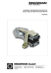
Thread Cutting Head
Type:
WHK-S3
with roller bearing
and brake
744 403 00
Thread Cutting Head
Type:
WHK-S3
Table of contents
1.0
2.0
3.0
Principle of die head operation
2
Application of die head
3
A. Cutting of taper pipe threads
B. Cutting of parallel pipe threads
3
3
Handling of die head
4
A. Co-operation of the head components
B. Inscription of the chasers and the head
C. Changing the holders
D. Changing the chasers
E. Grinding of the chasers
F. Setting the chasers
4
5
6
6
7
10
Thread cutting
12
A. Setting of the thread diameter
B. Selecting the cutting speed
C. Coolant and lubricant
D. Nomogram for determination of cutting speed
E. Nomogram for determination of helix angle
12
12
14
15
16
5.0
Faulty threads and their causes
17
6.0
Instructions for the use of the Setting table
19
7.0
Instruction for using the table of chaser holders
19
4.0
8.0
Attachments
20
A. Setting table for thread cutting heads WHK-S3
B. Holder Table
C. List of Spare Parts
D. Drawing of WHK-S3 (744 403 00)
E. Drawing of the chaser holder (740 800 00)
F. Adjusting device
G.Hanging up instruction
H. Application of die head WHK-S3
1
20
24
25
27
28
29
30
31
Thread Cutting Head
Type:
WHK-S3
1.0 Principle of die head operation
The die head operates with four tangential chasers. In
order to have a large working range and to adapt the
chasers to the screw pitch as closely as possible there
are various Sets of chaser holders which are
interchangeable.
Via cylindrical holder sliding pieces in the form steps,
the cutting pressure is transmitted to the eccentric
ring. As soon as the thread length is reached the latter
slides from the step so that the die head is opened and
reverse traverse may take place without any
difficulties.
These is to wind that a security trip is provided (see
drawing GSK 22 for WEK-S8 respectively drawing
GSK 19 for WHK-S3), at the working spindle, an
which the chaser die head is mounted.
This security trip avoids a complete re-sliding of the
die stock ring and is only to be removed for changing
of the holders.
This die head has been used successfully in hard
working conditions.
2
2.0 Application of die head
The die head is supplied in special execution for
automatic pipe cutting machines. Due to the
Operation method the die head with the working
spindle has to be axially moved to be machined. As
the movement of the die head is axial the operations:
closing, thread-cutting and opening are effected by
stops. These adjustable stops mounted on stationary
guide bars control the die head through the closing
ring located by roller bearing rings. The head is
equipped with a brake and two pawl-devices to avoid
an undesired opening of the head.
It is necessary that the machine is having an electrical
locking which avoids a return of the spindle sleeve, if
not the front position of the spindle sleeve have been
reached before. This security-locking must also be
active while setting-up reaching the end-position then
the unlocking of the locking catch will be left undone.
By means of this a damaging of the chaser die head
may occur.
All external Pipe Threads stated in holder table on
page H1 can be cut.
A. Cutting of taper pipe threads
Cutting of taper pipe threads is effected in a
continuous way. According to the taper of the thread a
taper cam ring, chaser holders with taper sliding and
taper chasers are required.
B. Cutting of parallel pipe threads
Cutting of parallel pipe threads is effected by a
cylindrical cam ring and chasers for cylindrical
threads.
For the application an control of the chaser die head
you should take in band our dimension drawing GSK
22 for WEK-S8 respectively GSK 19 for WHK-S3. First
you have to clamp the adjustable trips, the chaser die
head must have this position, where he is opening
immediately afterwards (the collar ball bearing
touches the trips), e.g. cutting procedure is finished,
the chasers have only to be swung out of the
component. Then both locking devices will be
clamped an the guide bars under consideration of the
dimension 50 m for WEK-S8 respectively 53 mm for
WHK-S3. For opening the locking devices earlier than
the chaser die head it is necessary to displace the
roller accordingly.
3
Thread Cutting Head
Type:
WHK-S3
3.0 Handling of die head
A. Co-operation of the head components
the slinding pieces (62). If the die-stock ring was
pushed back far enough, they are swung out of the
holders guides and removed from the head without
loosening the holder guides.
The die head consists of four basic components:
1. Die-stock
Die-stock (16) is fastened with four studs (23) and nuts
(24) to the headstock spindle of the Thread CuttingMachine, with the nuts being accessible behind the
spindle flange. On its face side it bears the hardened
die-stock plate with internal hexagon screws (28).
This takes the holder bolts (27) on which are mounted
the chaser holders. The holders are guided in holder
guides (29), which should not be screwed off without
reason. Pressure bushes (17), by means of springs
(18), press the holders to the exterior. Their movement
is limited by bolts (19). The feather key (20) fitted an
the die-stock serves for preventing the die-stock ring
from distortion and receives the contact pressure of
the brake.
4. Roller bearing ring
The exterior ring (42) is for axial movement of base
ring.
5. Chaser holders
The chasers have a parallel thread profile, i.e.
threads, which have not the same diameter but the
same pitch can be cut with a set of chasers; e.g. M 6
and M 12 x 1, where, of course, according to the
different helix angles and diameters two different
holder types have to be used.
Throat long
2. Die-stock ring
The eccentric casing (4) with eccentric ring (1) inserted
is connected to guide ring (10) by means of the four
internal hexagon screw (9). This unit is called diestock ring. The guide ring being guided along the
feather key (20), the die-stock ring can only be shifted
axially an the die-stock. In the eccentric casing the
eccentric ring is clamped with clamping screw (7) and
tension nut (8). When this clamping is released, the
eccentric ring may be displaced towards the die-stock
ring by turning adjusting pinien (5) by which is
obtained a change in diameter.
Throat medium For work pieces without oversize,
blank or pre-worked parts, run-out
of thread approx. 3 x pitch
Throat short
Chaser with
long throat
Chaser with
medium throat
8.5 mm
2.4 mm
2.2 mm
33°
M 2.0 P
For work pieces with threads against
shoulder, run-out of thread approx.
2 x pitch
In exceptional cases for materials with larger oversize,
a throat can be supplied with two throat bevels. The
longer the throat, the better the thread-surface and
the longer the chaser-life.
When choosing the throat, however, it must be
absolutely considered, that the chasers with their side
faces do not contact the work piece.
3. Holders
Holders (60) taking the chasers are mounted an
holder bolts (27) and are locked axially by the holder
guides fastened to the die-stock plate. For receiving
pressure they bear an the eccentric ring together with
Chaser with
short throat
For work pieces in milled material or
with oversize, run-out of thread
approx. 4 x pitch
1
15°
18°
M1P
1
M 1.5 P
1
Standard tool rake angle 20°
tool rake angle 25°
tool rake angle 5°
Grinding angle 7°
Grinding angle 5°
Grinding angle 2°
4
Thread Cutting Head
Type:
WHK-S3
B. Inscription of the chasers and the head
The thread form, the pitch and the number of the
chasers within the set are engraved. If on the position
* a production-number is engraved only chasers with
the same number in one set have to be used.
Examples for the Designation of the Thread at the
Chaser :
Fig. 2 Inscription of the Chasers
Set-Number*
1
P
M 0,7
M 2,0 P
Chasers for all metric threads as per valid DIN 13 with
a pitch of 2,0 mm
W 11 GG
Chasers for all Whitworth-threads as per DIN 11 and
for all cylindrical Whitworth-pipe-threads as per DIN
259 with a pitch of 11 threads per Inch
Number of
Chaser
Thread Form
Pitch
* If here a production-number is engraved only chasers
with the same number in one set have to be used.
R 11 GG K 1:16 A OV
Chasers for conical Whitworth-pipe-threads with
cone 1:16 as per DIN 2999 and 3858 with a pitch of
11 threads per Inch for conical thread cutting on
chaser width i.e. without device.
Fig. 3 Chaser Angles
a = Clearance Angle
b = Lip Angle
R 11 GG K 1:16 A
Chasers for conical Whitworth-pipe-threads with
cone 1:16 as per DIN 2999 and 3858 with a pitch of
11 threads per Inch for continuously conical thread
cutting i.e. with device.
TR 10 - 14 x 3
Chasers for trapezoidal threads as
per DIN 103 ISO with a diameter of 10 to 14 mm and
a pitch of 3 mm
g = Rake Angle
d = Cutting Angle
g
b
a
The holders can only be used in sets and cannot be
exchanged against those of other sets. The
production number is marked with “A” e.g. A 6 (letters
and numbers between 1 and 100).
Underneath is the holder type ("B") e.g. WE 21 B or
WH 21 B.
The holders of a set are marked with the numbers 1 to
4 and "C" fig. 2. As all holders are adapted to the
guides besides each bolt, on place "D", is the number
1 to 4. The range of holders can be looked up in the
holder table. Despite this, on the front of holder 1 in
place "E", under the holder type, the range of the
minor diameter, i.e. 8 28, is specified. In addition,
the holder angle is marked.
90°
d
5
Thread Cutting Head
Type:
WHK-S3
C. Changing the holders
3. Setting the chaser in the holder
Put the carefully cleaned holder (60) on guiding pin.
Clamping plate (63), fixing screws (64), and
adjusting screw (65) with stop (66) are already
loosely in the holder. Now slid chaser (70) into the
holder and clamp it slightly with fixing screws (64).
Take care that the chaser number corresponds to
holder number.
To change the holders, first you have to remove the
security trip (see GSK 22 for WEK-S8 respectively GSK
19 for WHK-S3), then it is necessary to turn the cam
ring so that the sliding key under the eccentric cam
freely move. The base ring has to be moved backward
so that the chaser holders can be swivelled and taken
off without loosening the holder guides (29). Before
mounting them again, it is necessary to clean and oil
the sliding surfaces. It is to observe that the pressure
bushings (17) work perfectly.
Now swing the complete holder up to stop pin by
which is retracted the feeler. For vertical adjustment
set dial gauge with the small hand-wheel so that the
feeler will touch the tip of the last cutting tooth. As a
matter of fact, the feeler must never touch the guide
teeth. Now you may advance the chaser by means of
adjusting screw (65) until the dial gauge reading will
correspond with the setting value given by the relative
setting chart (as regards the theoretical setting value,
setting beyond or below centre, see fig.8.
The chaser holders are marked 1 to 4 on the front of
place "C". The holders are to be used according to
marking “D”. To close the head use clamping ring
(51) which presses the sliding pieces (62) and the
head can be closed.
D. Changing the chasers
1. Removal of chaser from holder
For removing chaser (70) from holder (60) loosen the
two fixing screws (61), then it is possible to remove the
chaser by pushing it towards the cutting end. It will be
useful to place the chaser immediately into the
adjusting attachment which is clamped in any vice or
in the vice of the machine.
Care should be taken that both of the small pointer
for the millimetre graduation, and the big pointer for
the one hundredth reading, are in accordance with
the setting value. If for example the chaser shall be set
to the 1.75 setting value, the small pointer should be
between 1 and 2 and the big pointer should point at
75.
2. Setting the dial gauge
Replace stop pin by the relative setting gauge. Then
adjust the dial gauge in the following way: Insert it
into dial gauge holder and shift it axially until the
small pointer of the dial gauge is precisely pointing at
zero. Now tighten clamping screw but take care that
the movement of the feeler will not be hindered. Then
turn the dial of the gauge until the big pointer "g" will
likewise precisely point at zero. Having inserted again
stop pin in place of the setting gauge, the adjusting
attachment is ready for setting the chasers.
Next to this the fixing screws (64) may be locked
tightly but first tighten the frontal fixing screw in order
to avoid tipping. Moreover, it is advisable to retighten
afterwards adjusting screw (65). If the chaser should
be used up to such a degree that clamping plate (63)
is inclined to tilt during the tightening of fixing screws
(64) then it will be indispensable to add shim (71/72).
This shim is profiled like the chaser dove-tail and can
be supplied in various lengths. A chaser set in this
way is now ready for cutting and the holder may be
taken from the setting attachment.
6
Thread Cutting Head
Type:
WHK-S3
E. Grinding the chasers
3. Layout of the grinding angle
The grinding angle is in a certain angle to the thread
profile and compensates the holder angle, the throat
bevel as well as the rake angle in such a way, that the
cutting edge again runs in a parallel relation to the
axis of the work piece and thus an accurate thread
profile can be cut. Accordingly, the grinding angle
consists of holder angle and a supplementary angle.
For the most usual rake angles of 20° and 25° the
supplementary angle for angular threads can be
taken from the following table for normal throats.
The chasers being the real cutting tool of the whole
thread cutting head system are supplied with a
corresponding throat as already described in section
a) and b). This throat will not be modified and will exist
during the whole chaser-life.
The chaser is reground on its front, which is also the
true rake. This regrinding differs only little from the
regrinding of conventional tools known. There are
only some points to be considered in particular, which
especially are determined for tangential chasers.
1. Possibilities of grinding
The regrinding of the chasers can be made on every
universal tool machine. As a help WAGNER®
supplies a grinding fixture, which permits the
clamping of the chasers as well as the
setting of the necessary angles. If no tool grinding
machine is available we recommend to use a
WAGNER® -chaser grinding machine.
As grinding wheels cone-shaped cup grinding wheels
EKW 60 Jot, with strengthened edges suit best. These
wheels can be supplied by WAGNER®.
Rake Angle°
Free cutting steels
Structural steels up to 500 N/mm²
Structural steels > 500 N/mm²
High-alloyed steels (stainless)
Tubes
Malleable iron-fittings
Gray cast
MS 58
MS 60-62
Bronze
Copper
Aluminium-alloys
16 - 25
16 - 25
16 - 25
22 - 30
20 - 25
15 - 22
10 - 20
- 4 - 10
8 - 20
8 - 20
20 - 30
18 - 30
Grinding Angle
20°
25°
long
medium
short
3.0°
3.5°
5.0°
3.8°
4.5°
6.5°
Grinding Angle =
Holder Angle + Supplementary Angle
In order to determine the supplementary angle for
other rake angle values and special throats the
nomogram in fig. 4 can be used as follows:
To look for the throat or for the corresponding throat
angle on the right scale, make a straight line from this
point across the corresponding rake angle on the
medium scale to the left scale. There, the
supplementary angle can be read.
In special cases, when cylindrical threads without
guide teeth are cut, the supplementary angle is not
necessary. Then it follows:
2. Selection of the rake angle
The rake angle depends as in case of all cutting
operations on the material to be cut, on the
possibilities of lubricant and of coolant and on the
cutting speed.
Standard Time Data
Material
Throat
Grinding Angle = Holder Angle
When cutting conical threads on the width of the
chaser, which is effected without guide teeth also a
supplementary angle has to be used, which
compensates the conical form of the chaser, so that
the whole cutting edge is again parallel to the axis of
the work piece. This supplementary angle amounts to
1° in case of a thread with cone 1 : 16, 1°.
When cutting conical threads with continuously
opening thread cutting heads (type Z-K, Z-GK and
GEWE), generally chasers with guide teeth are used.
In special cases e.g. high cutting speeds and in case of
a formation of built-up edges chasers without guide
teeth can bring an improvement.
In special cases e.g. when working with steels with a
low resistance St 37 and similar steels, stainless
materials, copper and aluminium, it may be better not
to grind the true rake on a plain face but to provide it
with a radius (so-called flute), which essentially
favours the outlet of the chips in case of these
materials.
7
Thread Cutting Head
Type:
WHK-S3
Fig. 4 Nomogram for Determination of Supplementary Angle
Top Rake <
Cutting Angle <
p
To
Supplementary Angle
g
ke
Ra
Angle of Throat
Standard Throats
Angle of Throat <
short
medium
long
Example
Angle of Throat:
18° (medium)
Top Rake:
15°
Results to
Supplementary Angle: 2.6°
4. Checking the grinding angle with the setting
device
The grinding angle can always be controlled in the
setting device. The cutting edge of the chaser should
be parallel to the measuring pin of the dial gauge,
and the measuring pin is parallel to the axis of the
work piece.
In practice it has been shown, that for most materials
this parallel position of the cutting edge of the chaser
to the axis of the work piece gives the best results. In
some cases for instance for stainless materials it may
be necessary to reduce the grinding angle,
sometimes even to the negative domain, whereas an
increase is not recommended.
Fig. 5 Checking the Grinding Angle with the Setting Device
stylus
dial gauge
8
cutting teeth parallel
cutting angle too low
8
cutting angle too high
Thread Cutting Head
Type:
WHK-S3
5. Grinding of the chasers
Fig. 6 Cutting Faces on the Chaser
Grinding without Guide Tooth
After selecting the necessary angles, according to
page 7 and page 8 the chasers can be ground. In
case of dry grinding you have to pay attention to a
moderate temperature of the chasers. On no account
the chasers must be immersed in water later. When
grinding wet a sufficient amount of coolant has to be
used. Mistakes may lead to appearance of hairline
cracks and to breaking out of the chaser cutting
edges.
Cutting Face
Grinding without guide tooth:
In fig. 6 and 7 on the left “f” is absent, i.e. the chasers
are ground straight on their face with the adjusted
angles.
a
Throat
Grinding with Guide Tooth
Cutting Face
Grinding with guide tooth:
See fig. 6 and 7, right.
Here the grinding consists of two phases of operation
Grinding of the Guide Foot (= Guide Teeth)
It is recommendable, that the guide tooth juts out as
less as possible (5 to 10 % of the thread-Ø) against
the cutting teeth. As grinding angle the holder angle is
adjusted and as rake angle a value between 0° and
the selected rake angle is adjusted. This in not too
important, as the guide teeth do not cut but lay
beyond the centre of the work piece and do only
guide.
a
Throat
Fig. 7 Chaser Forms for Thread Cutting
Grinding of the Cutting Teeth:
The angles selected respect-tively determined of page
7 and page 8 are now adjusted exactly. The cutting
teeth are ground in a sharp-edged way between the
first and the second complete cutting tooth. The
sharp-edged execution of the corner is most
important, as if the flank of the first tooth is ground
chips can gather and this will lead to a breaking out of
this tooth and also to a production of unclean
threads.
without Guide Tooth
Jutting out of the guide tooth:
Guide teeth that are too long can also result in
gathering of chips and as the guide teeth are laying
too far beyond the centre line of the work piece small
thread diameters cannot be adjusted. Too short guide
teeth do not guide enough. If you work with a lead
screw feed, it is not absolutely necessary to use guide
teeth.
Cutting Teeth
with Guide Tooth
Guide Tooth
9
Cutting Teeth
Thread Cutting Head
Type:
WHK-S3
F. Setting the chasers
To ensure that the chasers are uniformely set in the
correct relationship to the work piece, they are
adjusted in a setting device by means of a dial
indicator. This setting is comparable to the setting of
the lathe tool on the center height. The corresponding
values can be obtained from the setting table.
Fig. 8 Setting of the Chasers
g = Rake Angle
d = Cutting Angle
a = Clearance Angle
b = Lip Angle
g
b
Determination of the setting value
The setting value results from the setting length which
is the gauge from the centre of the holder to the point
of contact at the core diameter of the thread.
a=0
Cutting Edge Centered
The setting value so depends on the core diameter of
the thread and varies according to the diameter.
To ease the setting process these setting lengths were
converted into setting values, which can be obtained
from the holder tables. By using the adjusting device
the values are transmitted onto the chasers.
g
b
a
In order to determine the setting value of the thread
you wish to cut you have to look for it in the holder
table. There you will find on the right hand-side a
column called »setting values« where the setting value
using the appropriate gauge is listed.
Cutting Edge Below Center
g
The listed setting values are always positive values
according to the adjusting gauge diameter stated on
top of the setting value column.
b
a negative
A setting according these table values means that the
cutting edge of the threads cuts exactly on the
centreline of the work piece.
Cutting Edge Above Center
In practice, it has been shown that the value has to be
suited to the different materials. The following data
may serve merely as guidelines, because other factors
like for instance centreline accuracy between cutting
head and work piece, clearance of slide and shaft,…
have a bearing on the setting value.
Fig 9 Setting Value and Setting Length on the Chaser
Points of Contact
Chasers
The setting value has to be increased by the
determined value from the following table.
Holder Pin
Setting Length
Work Pieces
10
Thread Cutting Head
Type:
WHK-S3
Material or form of the
work piece
Addition in %
of the diameter of
the work piece
Free cutting steels
Structural steels up to 500 N/mm²
Structural steels more than 500 N/mm²
High-alloyed steels (stainless)
Tubes, cylindric threads
Tubes, conical threads
Gray and malleable cast
MS 58
MS 63, Bronze
Copper
Aluminium-alloys
Example
Thread M 10 x 1
Material 9 S 20 K
Setting value from holder table
+ 1.5 % von Ø 10
Setting of the Chasers
1-2
1
0.5 - 1
0 - 0.5
0.5 - 2
1- 2
1- 2
2
0.5 - 2
0.5 - 1
0.5 - 1
0.60
0.15
+ 0.75
The chasers must not be increased more than
absolutely necessary, that means until chatter marks
are no more visible on the thread.
An over-increase of the threads leads to a greater
friction between tool and work piece which causes
an increase of temperature and bigger abrasion.
11
Thread Cutting Head
Type:
WHK-S3
4.0 Thread cutting
A. Setting of the thread diameter
Material
The diameter of the thread to be cut is set by turning of
the eccentric ring (1). Setting is continuous.
Setting is effected with die head closed according to a
thread sample or a bolt corresponding to the core
diameter.
To adjust the diameter it is necessary to loosen
clamping screws (7) being situated on the front side by
means of the square socket wrench (52).
Then the adjusting pinion (5) is turned until it will no
longer be possible to turn the thread sample
manually. Afterwards the clamping screws (7) are
retightened. A possible readjustment would be
necessary alter having checked the first thread being
cut.
Cutting Speeds
[m/ min]
Free cutting steels
Structural steels up to 500 N/mm²
Structural steels > 500 N/mm²
High-alloyed steels (stainless)
Tubes
Malleable iron-fittings
Gray cast
MS 58
MS 60-62
Bronze
Copper
Aluminium-alloys
15 - 40
10 - 40
5 - 15
3-8
15 - 40
10 - 30
10 - 25
30 - 60
30 - 50
20 - 50
15 - 40
20 - 60
Scale "f" only serves for finding a once made-out
position of the eccentric ring again.
For threads on pipes and fittings there is no large
choice of materials. Here the cutting speed is ranging
from 10 to 20 m/ min. However, where it is
permissible to let the pipe project from the vice by a
greater length so that it sings during the cutting
operation, it will be possible to reach cutting speeds
between 30 and 40 m/ min. Even in dry cutting.
However, the flank of the thread is no longer clean.
One may say on principle that an improved surface
quality will always be bought at the price of a reduced
cutting speed.
The proper cutting speed for each case has to be
found by trial.
B. Selecting the cutting speed
1. Choice of cutting speed
From turning the reader is used to obtain precise
Information on the cutting speed with respect to using
various materials and tools. In thread cutting such an
Information is not possible because the cutting speed
depends on too large a number of factors, e.g. on the
material, on diameter, depth of thread, pitch, setting
measure, top rake, grinding angle, and last not least
on the desired cleanness of the thread flanks.
Therefore, the following chart is just a trial to give
approximate guidelines. Starting with them it should
be possible to try out the cutting speed for each
individual case.
The first column of the chart contains a few materials
only. Not listed materials should be ranged between
such which were listed.
The second column gives speed data for cutting
angular threads. For this, please bear in mind that the
lower cutting speed refers to the larger diameter while
the higher cutting speed should be applied to smaller
diameters.
For fine threads the following may serve as a rule of
thumb: Look up standard threads and find out that
thread which has the same pitch as should have the
fine thread you intend to cut, and select the same
cutting speed that would be favourable for the normal
angular thread.
In the third column “Acme threads” is likewise given a
speed range which should be applied in accordance
with he work piece diameter (the smaller the
diameter, the greater the cutting speed).
On the usage of page 12 cutting speed chart:
The left-hand scale "D" is graduated on one side in
millimetres, and an the other side in inches. Outside
diameters, and finally further to the right there are the
outside diameters for Whitworth pipe threads. The
scale in the middle indicates the speeds (it is
recommended to mark the possible speeds of the
machine in nomograms), and on the right side is the
scale for the cutting speeds to be calculated.
When drawing a straight line from the desired
diameter through the desired speed you will hit upon
the relative cutting speed. The example outlined
shows:
d = 20 mm
12
® n = 64/ min ® v = 4 m/ min
Thread Cutting Head
Type:
WHK-S3
C. Coolant and lubricant
2. Calculating the helix angle
Usually it is not necessary to know the helix of a thread
because the threads are listed in the holder chart in
such a way that the holder corresponding to each
thread may be read anyway. However, for special
cases that are not listed in the holder chart, you may
quickly calculate the pitch angle of the thread by
taking recourse to page 16. In doing so, take care that
the diameter to be applied to the thread in question
should not be the outside diameter but the medium
diameter, i.e.:
d2 =
In principle, when thread cutting we work with cooling
lubricants. A good supply of cooling lubricants is
necessary.
Our recommendation: degree of greasiness: approx.
8 - 12 %. Diluted soluble oil can be used. However,
cutting oil can lead to a considerable improvement of
the cutting process and of the thread Gut.
There is the risk that parts could bind, when using
synthetic cooling emulsion. In this case, function of
the thread cutting head is reduced.
(d + d3)
2
In special cases we recommend to cooperate with the
manufacturing company.
d2 = medium diameter
d = outside diameter
d3 = core diameter
Helix angle φ is calculated according to the relation:
P
tg φ = (π × d )
2
P = pitch of the thread [mm]
d2= medium diameter (or flank diameter respect.)
The left side of the GSL 52 nomogram contains the "P"
scale, in the middle is the "d" scale, and on the right
side “φ” scale. For the latter the angle on the left side
is given in centigrade, while on the right side φ can be
read in degrees and minutes.
After all, you look up the pitch of the desired thread on
the “P” scale and the medium diameter on the "d2”
scale. Connect the two points by a straight line and
you will hit upon the relative helix angle on the “φ”
scale.
The example outlined in the chart shows the
calculation of the helix angle for M 16 thread.
The mean diameter is:
d2 =
(d + d3)
= (16 + 13.402)/ 2 = 14.701 mm
2
(Pitch diameter likewise 14.701 mm)
Pitch P = 2 mm
Connecting line (P - d2) gives a helix angle φ of 2.49°
or 2° 29'.
In view of the fact that the medium diameter only
deviates very slightly from the flank diameter it is
permissible in most cases to calculate with the flank
diameter.
13
Thread Cutting Head
Type:
WHK-S3
D. Nomogram for determination of cutting speed
mm d inches
B.S.P
n 1/ min
v m/ min
v=
Õ×d×n
1000
d = Major diameter [mm] in B.S.P
n = 1/ min
v = Cutting Speed [m/ min]
14
Thread Cutting Head
Type:
WHK-S3
E. Nomogram for determination of helix angle
mm P t.p.i
Decimal j degrees
minutes
angles
d2 min
tan j = h d
h = Pitch [mm t.p.i]
d = Effective diameter [mm]
j = Helix Angle [degrees]
15
Thread Cutting Head
Type:
WHK-S3
5.0 Faulty threads and their causes
Faulty threads can have several causes:
1) The sequence of chasers from 1 to 4 has not been observed. This results in a completely miscut thread. In case
the chasers have been set in the reverse sense, i.e. 4, 3, 2, 1 no thread results at all.
2) Chasers with different serial numbers may have been used. Then the accurate offset of the four chasers is no
longer guaranteed, thus resulting in faulty threads.
3) Chasers may have been mixed up, e.g. it is impossible to cut a cylindrical thread with a chaser for taper threads.
4) The wrong setting value or grinding angle may have been chosen. This may result in a thin thread, i.e. the
included angle is too small and the gap in the root is too wide.
5) Faults mentioned under items 1) to 4) were not made, however, the material to be cut requires different setting
values respectively grinding angle- and top rake values. In the following a number of faults are listed in order to
avoid faulty threads:
Fault
Cause
1. The thread is not concentric
The four chasers were not adjusted exactly to the
same setting value
The setting value was too small
The material was not concentric or sheared off
bevelled and the cutting Speed was too low
The top rake was too large
Length "f" of guide teeth in front of the working
face was too short
Alignment of work piece and thread cutting head
is not accurate enough.
2. Faulty lead
The lead angle of the chaser holder is incorrect.
To be compared with thread- and holder tables,
whether the correct holder was chosen for the
thread to be cut.
The grinding angle is incorrect.
The setting value is incorrect.
The slide of the machine offers too much
resistance or the feed rate is not correct.
The feed pressure is not correct in relation to the
lead.
3. Wrong included angel
Chaser was Set in the holder tilted
Churping plate and position of chaser to be
checked
4. Thread depth is too small
The grinding angle is too small or even negative
The setting value is too small
16
Thread Cutting Head
Type:
WHK-S3
5. Threads are of poor quality, flank surfaces
are rough
These faults can be due to the formation of a
built-up edge which is often caused by selecting
the top rake too low.
Chaser is blunt
Cutting speed is too high
Coolant resp. lubricant chosen is unsuitable
6. Continuous flutes alongside of the thread flanks
Offset fault to be checked
Do bear chasers and holders have the same
serial number?
Guide tooth does not begin exactly with tooth
space. The side of the first tooth of the guide
tooth must not be ground.
Chaser broken or blunt
7. Chatter marks on the thread
8. Thread is eccentric to shank
Work piece is clamped eccentrically
The work piece centre is not centrical to the
centre of the thread cutting head.
Setting value is too small
Cutting speed is too high
Too long clamped in the clamping vice
Top rake was too small for soft material
9. A multi-start thread is obtained
The chasers were not mounted in the correct
sequence
Heavy feed pressure may result in the production
of multi-start threads
when cutting fine threads of a comparatively
large diameter, the chasers will then continue
automatically to cut these multi-start threads
10. Chasers break out
17
Too much oversize
The material is not concentric or sheared off
The setting value chosen is too small
The cutting speed is too low
Thread Cutting Head
Type:
WHK-S3
6.0 Instructions for the use of the setting table
The values thus obtained provide a setting in which
the cutting edge of the chaser is accurately positioned
along, the centreline of the work piece. However, this
setting, does not always result in the production of
good threads.
To ensure that the chasers are uniformly set in the
correct relationship to the work piece, they are
adjusted in a setting jig equipped with a dial indicator.
An accuracy of a few hundredths of a millimetre may
be considered adequate. The desired values can be
obtained from the setting table to an accuracy of 0.05
mm. The top row lists a large variety of customary
threads. Since the setting value depends an the core
diameter (minor thread diameter), this is listed in the
first column. The second column gives the setting
length. This is value C + δ from fig. 3 on page 29, plus
the setting value from the third column of the setting
table (under the condition that the chaser is placed
exactly at the centre of the work piece as shown in fig.
6.)
It will often be necessary to select a larger setting
value (see fig. 8).
Especially when cutting soft material it is necessary to
place the cutting edge beyond the centre line of the
work piece, i.e. to increase the setting value if, for
example, no normal threads are obtained or the
flanks are very unclean when cutting with the normal
setting value. It is recommended to try whether an
increase of the setting value by 1 % of the diameter
has already good cutting results. If not, the chaser has
to be adjusted further. Depending on the type of
thread, the setting value had to be increased
occasionally up to 3 % of the diameter. But it must be
remembered that the cutting temperature is always
increased if the chaser is threading beyond the centre
line of the work piece, as in this setting the chaser
presses in the flanks. The setting value should
therefore not be increased more than absolutely
necessary to produce the desired clean threads
To determine the setting value of a thread not listed in
these tables, it is merely necessary to know the core
diameter. This core diameter should be interpolated
in the appropriate position in the first column, the
setting length and the setting value will then be found
in adjacent positions in the second and third columns
respectively.
18
Thread Cutting Head
Type:
WHK-S3
7.0 Instructions for using the table of chaser holders
The table of chaser holders enables the user to select
the suitable holder in accordance to his requirements.
This avoids time-consuming enquiries.
The head of the table contains a large number of
standard threads which include not only German
threads but also English and American types.
American pipe threads appear under the description
NPT.
The first column lists all normal chaser holders which
can be supplied for any particular thread-cutting
head.
The second column lists the holder angle, following a
column giving the dimensions of the chaser. In this
last column the first two figures refer to the crosssection of the chaser and the last figure to the length
of a new chaser. Re-grinding will, of course, reduce
this length. The minimum and maximum core
diameters which can be cut with any given holder is
listed in the fifth column.
19
20
49,58
48,58
47,53
46,43
45,25
44,00
42,64
41,15
39,49
37,56
35,20
31,77
22,23
18,80
16,44
14,51
12,85
11,36
10,00
8,75
0,70
0,75
0,80
0,85
0,90
0,95
1,00
1,05
1,00
0,95
0,90
0,85
0,80
0,75
0,70
0,65
0,60
0,55
0,50
110,70
110,75
110,80
110,85
110,90
110,95
111,00
111,05
111,00
110,95
110,90
110,85
110,80
110,75
110,70
110,65
110,60
110,55
110,50
Kern-Ø des Einstelllänge Einstellwert
Lehre 14Ø
Gewindes
Einstellwert Einstellwert
Lehre:
Lehre:
R 1 ½”
R 1 ¼"
R ¾ · R1
R ½"
R 3/8
WhitworthRohrgewinde
DIN 2999 ISO 7/1
1 ½” - 11 ½
1 ¼” - 11 ½"
¾" - 14 · 1" - 11½
½" - 14
3/8 - 18
NPT, API *
Amerikanische Rohrgewinde
Thread Cutting Head
Type:
WHK-S3
8.0 Attachments
A. Setting table for thread cutting heads WHK-S3: Holder: WH 21B, 22B
21
68,45
67,86
67,26
66,65
66,03
65,39
64,75
64,09
63,42
62,73
62,03
61,31
60,57
59,82
59,04
58,24
57,42
56,57
55,69
54,77
53,82
52,83
51,79
50,70
49,54
48,30
46,96
45,50
0,35
109,75
109,80
109,85
109,90
109,95
0,00
0,40
110,40
110,35
110,00
0,45
0,05
0,50
110,50
110,45
110,05
0,55
110,55
0,10
0,60
0,15
0,65
110,60
110,15
0,70
110,70
110,65
110,10
0,75
0,20
0,80
110,80
110,75
0,25
0,85
110,20
0,90
110,85
0,30
0,95
110,95
110,90
110,30
1,00
110,25
1,05
111,05
Einstellwert
Lehre 14Ø
111,00
Einstelllänge
Kern-Ø
des Gewindes
Einstellwert
Lehre:
Einstellwert
Lehre:
R 2¼”
R 2"
WhitworthRohrgewinde
DIN 2999 ISO 7/1
2" - 11½
NPT, API *
Amerikanische Rohrgewinde
Thread Cutting Head
Type:
WHK-S3
A. Setting table for thread cutting heads WHK-S3: Holder: WH 23B
22
88,74
87,90
87,05
86,16
85,24
84,28
83,28
82,23
81,13
79,97
78,73
77,39
75,93
74,31
72,47
70,27
67,34
54,66
Kern-Ø
des Gewindes
3,95
3,90
3,85
3,80
3,75
3,70
3,65
3,60
3,55
113,95
113,85
113,80
113,75
113,70
113,65
113,60
113,55
4,00
114,00
113,90
4,10
4,05
114,10
4,15
114,15
114,05
4,25
4,20
114,25
4,30
114,30
114,20
4,35
Einstellwert
Lehre 14Ø
114,35
Einstelllänge
Einstellwert
Lehre:
Einstellwert
Lehre:
R 3”
R 2 ½”
WhitworthRohrgewinde
DIN 2999 ISO 7/1
3" - 8
2½” -8
NPT, API *
Amerikanische Rohrgewinde
Thread Cutting Head
Type:
WHK-S3
A. Setting table for thread cutting heads WHK-S3: Holder: WH 24B
Thread Cutting Head
Type:
WHK-S3
A. Setting table for thread cutting heads WHK-S3: Holder: WH 25B
Einstelllänge
Kern-Ø
des Gewindes
Einstellwert
Lehre 14Ø
88,35
89,02
112,35
2,35
89,67
112,30
2,30
90,32
112,25
2,25
90,95
112,20
2,20
91,56
112,15
2,15
92,17
112,10
2,10
92,77
112,05
2,05
93,36
112,00
2,00
93,94
111,95
1,95
94,51
111,90
1,90
95,07
111,85
1,85
95,62
111,80
1,80
96,17
111,75
1,75
96,71
111,70
1,70
97,24
111,65
1,65
97,77
111,60
1,60
98,29
111,55
1,55
98,80
111,50
1,50
99,30
111,45
1,45
99,80
111,40
1,40
100,30
111,35
1,35
100,79
111,30
1,30
101,27
111,25
1,25
101,75
111,20
1,20
102,22
111,15
1,15
102,69
111,10
1,10
103,15
111,05
1,05
103,61
111,00
1,00
104,07
110,95
0,95
104,52
110,90
0,90
104,96
110,85
0,85
105,40
110,80
0,80
105,84
110,75
0,75
106,28
110,70
0,70
106,71
110,65
0,65
107,13
110,60
0,60
107,55
110,55
0,55
107,97
110,50
0,50
108,39
110,45
0,45
108,80
110,40
0,40
109,21
110,35
0,35
109,61
110,30
0,30
110,02
110,25
0,25
110,42
110,20
0,20
110,81
110,15
0,15
111,20
110,10
0,10
111,59
110,05
0,05
111,98
110,00
0,00
Einstellwert Einstellwert
Lehre:
Lehre:
Amerikanische Rohrgewinde
WhitworthRohrgewinde
DIN 2999 ISO 7/1 NPT, API *
R 3½”
4” - 8
R 4”
23
24
740804
WH25B
740803
WH24B
740802
WH23B
740801
WH22B
740800
WH21B
Designation
Product-No.
0.67°
0.75°
0.92°
1.08°
1.50°
Holder angle
in °
Chaser holder
25x12x100
25x12x100
25x12x100
25x12x100
25x12x100
Dimension
of chasers
90 - 110
66 - 87
47 - 67
28 - 48
10 - 30
Cutting range
Core diameter
in mm
M 95-110 x 2
M 95-110 x 1.5
M 72.75.76.78.808.82.85.88 x 3
M 70.72.75.76.78.80 x 2
M 62.64.65.68 x 3
M 55.56.58.60 x 3
M 40.42.45.48.50 x 3
M 32.33.34.35.36 x 2
M 23.24.25.26.27.28 x 2
M 18.19.20.21.22 x 1.5
Metric fine threads
DIN 246, 247,
516- 519
2 ¼"
3"
3 ¾"
4"
3 ¼" 3 ½"
2 ¾"
2 3/8" 2 ½"
2"
1 5/8" 1 ¾"
1 ½" - 12
1 ½“
(1 ¼" - 12)
(1 3/8" - 12)
1 ¼“ 1 3/8"
1 1/8"
(1 1/8" - 12)
¾" 7/8"
1"
1 - 12
(1 - 14)
½"
5/8"
7/8 - 14
¾ - 16
NF
UNF
4-8
3½-8
3-8
2½-8
2 - 11½
1 ½ - 11 ½
1 ¼ - 11 ½
(1 - 11 ½)
3/4 - 14
½ - 14
NPT
American National Threads
3/8”
Whitworthpipe threads
DIN 259/ 2999
W 2 ½" x 1/14
W 2" x 1/14”
W 1 ½" x 1/14
W1 ¼" x 1/16
W1" x 1/16”
W3/4" x 1/16”
W 5/8" x 1/18"
Conduit
threads
Pg 48
Pg 42
Pg 36
Pg 29
Pg 21
Pg 16
Pg 13,5
Pg 11
Pg 9
Steel conduit
pipe threads
DIN 40430
Thread Cutting Head
Type:
WHK-S3
B. Holder Table for thread cutting head WHK-S3
Thread Cutting Head
Type:
WHK-S3
C. List of spare parts
WAGNER thread cutting head WHK-S3 with special locking collar
Part-no. 74440300
pos.
piece
part-no.
description
1
2
3
4
5
6
7
8
9
10
11
12
13
14
15
16
17
18
19
20
21
22
23
24
25
26
27
28
29
30
31
32
33
34
35
36
37
38
39
40
41
42
43
44
45
46
47
1
1
1
1
1
1
3
3
4
1
1
1
1
1
1
1
4
4
4
1
2
1
4
8
1
4
4
4
4
8
4
1
4
8
1
1
1
5
1
1
1
1
1
1
60
12
1
70989000
70909000
02020004
70995400
70990800
02882001
70990400
03021003
02015218
70817400
70834800
70834900
02048208
02882003
03011701
70817300
70808800
03310356
02030157
70997000
02020209
02160071
02040362
02061009
70991000
70808700
70808600
02016260
70995100
02121310
02016257
77944700
02043256
02043206
77941800
77942300
78002800
02320111
02112156
78054500
77944300
74436800
77944400
77944600
02460135
02015110
02882001
excentric ring
pointer
screw M3x8
excentric casing
adjusting pinion
ball grease nipple
clamping screw
clamping nut
internal hexagonal screw M10X70 DIN912
guide ring
square nut
square nut (counter nut)
handless screw M8X25 DIN915
ball grease nipple
internal hexagonal screw M10X15
die stock head, group complete
pressure bushing
pressure spring 2,5 X 13,5 X 60,0
shank screw M 6X12 DIN 427
sliding key
countersunk machine srew M 8 X 20 DIN 63
adjusting spring
studs M 16 X 50 DIN 939
nuts M16 DIN 934
flange
bushing for holder bolts
holder bolts
internal hexagonal screw M12X40 DIN6912
holder guides
cylindrical pins 6 X 24 DIN 1474
internal hexagonal screw M 12X 25
cover ring
handless screw M 12X12 DIN 551
handless screw M 10X12 DIN 551
threaded bushing
pressure screw
bolt for spring
cup spring
cylindrical pin M6 X 8 DIN 7
ball bearing
internal ring of ball
external ring of ball
ring of ball
cage of ball
ball
internal hexagonal screw M6X30 DIN912
ball grease nipple DIN71412
25
Thread Cutting Head
Type:
WHK-S3
C. List of spare parts (cont.)
WAGNER thread cutting head WHK-S3 with special locking collar
Part-no. 74440300
pos.
piece
part-no.
50
51
52
53
54
55
80
81
82
83
1
1
1
1
1
3
1
1
1
1
03889003
70997100
02675005
03697006
03697007
02048265
02033002
73949200
02015259
02015221
60
61
62
63
64
65
66
67
68
69
71
72
70
4
4
4
4
8
4
4
4
1
1
4
4
4
02016054
*
*
02015209
70511700
70511800
02121360
02677005
02677007
70807800
73165700
description
accessories head
pressure lubricator
clamping ring
hexagonal secket head wrench
hexagonal secket head wrench 8 DIN 6911
hexagonal secket head wrench 10 DIN 6911
handless screw M10X55 DIN915
mounting ring screw M10 DIN 580
internal hexagonal screw M 12X 25 DIN912
internal hexagonal screw M 10X 90 DIN912
chaser holders
internal hexagonal screw M 5X 16 DIN 6912
sliding pad
plate
internal hexagonal screw M 10X 25 DIN 912
adjusting screw
stop
grooves pin 8x24
hexagonal secket head wrench 5 DIN 911
hexagonal secket head wrench 8 DIN 911
shim 16X8X20
shim 16X8X45
chasers
* please give us the holder type
Adjusting device
Adjusting device
Part.-no. 77063900
Part.-no. 77063900
10 (E1)
20
30 (E2)
40 (E7)
50
60 (E4)
70
80
90
100 (E8)
110
120 (E3)
130 (E5)
140
(E6)
1
2
1
1
1
1
1
1
2
1
1
1
1
1
1
77924500
02044204
77925600
77924700
02160041
70259000
77924800
77924900
02020055
77925000
02116266
77925100
77925700
06525022
06525003
carrier for adjusting device WGK-WHK
grub screw DIN553 M 8x8
guiding pin WGK-WHKK
dial gauge holder WDK-WKK
feather key DIN6885-FORM A / 5x5x25
knurled head screw ZR16+22 M5 RD 8x11
screw WJK-WKKK M 10x65
washer WJK-WKKK RD 34/8,2x3
countersink screw M 4x10 DIN63
thumb wheel WJK-WKKK RD 34/8x8
split pin 4x32 DIN 1481
stop pin WDK-WKKK
setting gauge WDK-WEKK RD 14x65 DIN
caliper for dial gauge M2,5
dial gauge
26
Thread Cutting Head
Type:
WHK-S3
D. Drawing of WHK-S3 (744 403 00)
27
Thread Cutting Head
Type:
WHK-S3
E. Drawing of chaser holder (740 800 00)
28
Thread Cutting Head
Type:
WHK-S3
big pointer
dial gauge
clamping screw
setting gauge
guiding pin
F. Adjusting device
small pointer
dial gauge
holder
chas
er
holde
r no.
clamping plate
fixing screws
M 10 x 25
chaser
carrier for
adjusting device
hand wheel
small
pointer
big
pointer
chaser holder
chaser
no.
adjusting screw
dial gauge
clamping ring
chaser holder
no.
stop pin
Setting device with setting gauge
S4
chaser
S3
S2
S1
Grinding fixture for chasers
29
Thread Cutting Head
Type:
WHK-S3
G. Hanging up instruction
For mounting the die head the screw no. 61 has to be removed so that the ring screw 0.20330.02
can be inserted.
mounting of ring screw M10
no. 0.20330.02
30
Thread Cutting Head
Type:
WHK-S3
H. Application of die head WHK-S3
31
Gutenbergstraße 4/1
D-72124 Pliezhausen
Telefon (0 71 27) 97 33 00
Telefax (0 71 27) 97 33 90
Email: [email protected]
www.wagner-werkzeug.de