1
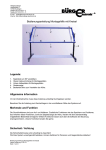
Operating instructions
LNT 250/150/D
Equipment designation:
LNT 250/150/D
Unit number:
2104104
Procedure number:
2343
Date:
17.04.2004
Wolfgang Bürger
Degerschlachterstr, 4
72768 Reutlingen
Telefon (07121) 96 86 73
Telefax (07121) 96 86 74
E-mail [email protected]
Internet http://www.buerger-electronic.de
Summary
First page
Side 1
Summary
Side 2
Catalog side
Side 3
Equipment illustration with legend of the control elements
Side 4
Operating instructions
Side 5
Safty regulation
Side 6
Guarantee card
Side 7
Declaration of Conformity
Side 8
POWER SUPPLY LNT 250/150/D
POWER SUPPLY LNT 250
SHORT DESCRIPTION
This 250 Watt laboratory power pack
is designed in the form of a switchedmode regulator. The secondary filter
ensures very low interference
voltage.
Output is by means of laboratory
safety sockets. Voltage and current
can be adjusted continuously
between 0 - final value.
MERKMALE
Permanently short-circuit proof
Power output max 250W
Thermal protective circuit
High efficiency
B
Low residual ripple
Low residual ripple
Can be switched in parallel
B
Technical data
Input
Input voltage
Overvoltage protection
Network failure time
Starting current
Soft start
General information
230V AC
VDR 275V
> 20 ms
12A
existing
Output
Maximum output
Continuous output
Output voltage
Output current
Residual ripple
System deviation
Overvoltage protection
Short-circuit current
Current limiting
Output voltage accuracy
250 W
200 W
0 - 100% adjustable
see table
< 1%
+/- 1%
VDR
see table
0 - 100% adjustable
0,5% during nominal
input voltage
Short circuit duration
Permanent
Typ/Order nos.
0 - 15V / 0 - 4A
0 - 30V / 0 - 8A
0 - 60V / 0 - 4A
0 - 120V / 0 - 2A
0 - 250V / 0 - 1A
Protective device
Overvoltage
protection
Storage temperature range
Operating temperature range
Load reduction
Weight
Dimensions
Connection
-30°C + 85°C
-20°C + 50°C
ab 40°C 2,5%/°K
ca. 4,75kg
42TE 3HE T2
Protective contact
plug 230V safety
laboratory sockets
Regulations
EN60950/
EN61000-3.2
Protective class
Radio interference class
Typical efficiency
II
Klasse B EN55022
ca. 80 – 90%
Options/Order no. Suffix
LNT250/15
LNT250/30
LNT250/60
LNT250/120
LNT250/250
Technical subject to change.
No adhesion for misprint.
Wolfgang Bürger
Degerschlachterstr, 4
72768 Reutlingen
Telefon (07121) 96 86 73
Telefax (07121) 96 86 74
E-mail [email protected]
Internet http://www.buerger-electronic.de
Analogue measuring instrument
Digital instruments
Sensor
Many course potentiometer
Interface analogue 0 -10V/DC
/A
/D
/F
/V
/S
POWER SUPPLY LNT 250/150/D
3
1
4
Designation
2
5
6
7
Assembly
Function
1.
2.
Digitally measuring instrument
Digitally measuring instrument
Voltage: 0 - 150V
Current: 0 - 1,6A
3.
4.
5.
6.
7.
Switch
On and off
Voltage range
Plus output
Minus output
Current
Drehknopf
Red socket
Black socket
Rotary knob
Operation in detail
1. Digitally measuring instrument for voltage 0 - 150V
2. Digitally measuring instrument for current 0 - 1,6A
3. Mains switch for switching device on and off
4. Rotary knob for voltage: voltage range: 0 - 150V.
5. Red socket: plus output
6. Black socket: minus output
7. Rotary knob for current: current range: 0 - 1,6A.
Note: output voltages over 50V can be dangerous for people.
The operating staff must be instructed accordingly.
Cooling and ventilation slots must not be covered.
B
Operating instructions
Current and voltage regulation
Voltage is kept constant up to the maximum current which is set. This voltage value is adjustable
with the voltage potentiometer. If maximum current is reached, the current is kept constant with the
current potentiometer and depending on loading the output voltage is reduced.
Network supply
The device is only designed for operation with 230V +/-10% alternating voltage (50-60Hz). Other
supply voltages are not implemented in this variant.
Cooling
The cooling slits of the device may not be covered (danger of overheating).
Connection
Laboratory safety sockets are only safe if the corresponding connector is used. If standard
connectors (4mm) are used, extra care must be taken.
Sensor (Option)
Sensors serve to compensate for external voltage drops in the power supply. This occurs in a
linear fashion up to 0.5V per power line, and limited between 0.5 - 1V (partial compensation).
Sensors are protected for a short time against load peaks. However, external users should not be
supplied with current via the sensors on any account.
Safety regulations
Live parts can be revealed if covers are opened or parts removed, except when it is possible to do
this manually. Connector components can also be live.
If it is necessary to open the device for adjustment purposes or for maintenance or repairs, the
device must be disconnected from all power sources.
If following this, adjustment, maintenance or repair have to be carried out when the device is open
and live, the work may only be carried out by a specialist who is aware of the risks involved.
It must be ensured that only fuses of the specified type and rating are used as replacements. Only
original spare parts may be used.
If it can be assumed that it is no longer possible to operate the device without danger, it must be
decommissioned and secured against unauthorised or unintentional use.
Please contact Bürger Electronic if it is necessary to make a repair.
In case of transportation damage, please note:
Check the consignment immediately for damage and completeness! Make sure that no parts
remain in the packaging and are lost as a consequence.
Have any damage to the goods or packaging confirmed on the waybill or delivery note by the
carrier immediately (rail, post, haulage company etc.).
If damage is only discovered when the parts are unpacked, leave the goods in the condition in
which they were when the damage was discovered. Make a complaint immediately to the postal
service, rail freight or road haulage company and ask for the damage to be assessed.
The assessment must take place:
• Within 24 hours for the postal service,
• Within 7 days for rail freight,
• Within 4 days in the case of haulage companies which carry out final delivery of rail freight,
• Within 6 days in the case of vehicle transport carried out by freight carriers or haulage
contractors.
Please retain all the packaging material in order to record the damage and have the following at
hand:
1. Transportation documents, such as waybill, copy of express freight card or similar
2. Certificate of damage of the transportation company
As the consignee, you are entitled to compensation for damage which occurs during
transportation, therefore you should make the application yourself.
Guarantee card
We offer the legally-specified guarantee on the device supplied for us. The official starting date for
the guarantee period is the date of invoice. However, the guarantee does not apply in case of
accident, negligence, improper use, non-observance of the operating conditions, non-observance
of the operating, test and service instructions or if repairs are made without the authorisation of
Bürger Electronic or if the device is used in a manner which is not approved by Bürger Electronic.
Bürger Electronic shall not be liable for indirect damage and reserves the right to decide on the
suitability of rework or exchange of the device.
Please retain the invoice and guarantee card!
If any defects occur before or after the end of the guarantee period, please send the device to us.
• Send devices in suitable packaging, in the case of heavy devices, please send in double
packaging.
• Enclose the invoice and a copy of the delivery note.
• Enclose the guarantee card, completely filled in.
• Please describe the defect precisely.
Guarantee card
Device: laboratory power pack
Type: LNT250/150/D
Date of purchase:
Invoice No.:
Name, First name:
Street:
Postcode and location:
Telephone:
Description of defect:
Repair under guarantee
Chargeable repair:
Repair up to €........................
above this amount, please send
an estimate