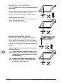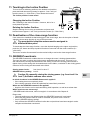
1
Tubular motor: GEIGER-SOLIDline Motor control: GEIGER-SoftZeroWireless (GU45..F02) for cassette awnings DE Original-Montage- und Betriebsanleitung EN Original assembly and operating instructions FR Notice originale de montage et d’utilisation ES Instrucciones originales de instalación y funcionamiento IT Istruzioni originali di installazione e funzionamento www.geiger.de EN EN 1 Index 1. General information...................................................................2 2.Guarantee...................................................................................2 3. Intended use...............................................................................3 4. Safety instructions.....................................................................3 5. Safety instructions for assembly.............................................4 6. Installation instructions............................................................5 7. Information for the specialist electrician.................................6 8. Bringing into service.................................................................6 9. Learning/deleting the radio code.............................................7 10. Adjusting the End Position ......................................................7 11. Teaching-in the Incline Position...............................................9 12. Deactivation of the close-range function................................9 13.GEIGER-Powertronic.................................................................9 14. Function description of radio motor......................................10 15. Radio codes.............................................................................. 11 16. Initiating End Positions...........................................................12 17. Obstacle detection...................................................................12 18. End position correction...........................................................12 19. What to do if…..........................................................................13 20.Maintenance.............................................................................13 21. Declaration of conformity.......................................................14 22. Technical data..........................................................................15 EN 23. Notes on waste disposal.........................................................15 1. General information Dear customer, By purchasing a GEIGER motor you have decided on a quality product from GEIGER. Thank you very much for your decision and the confidence placed in us. Before you put this drive into operation please observe the following safety instructions. It serves for the prevention of danger and for the avoidance of personal injury and damage to property. The installation and operating instructions contain important information for the installer, the specialist electrician and the user. Please pass on these instructions if you transfer the product. These instructions should be kept by the user. 2. Guarantee In the case of incorrect installation contrary to the installation and operating instructions and/ or constructional modification, the legal and contractual guarantee for property damage and product liability lapses. 2 EN Gerhard Geiger GmbH & Co. KG | 100W0536 en V001 1113 3. Intended use The motors of the model range SOLIDline (GU45..F02) with the SoftZeroWireless control are designed exclusively for the operation of cassette awnings. The motors may not be used for the operation of roller grilles, garage doors, furniture and lifting tools. GU 45 xx x Motor control Torque in Nm Motor diameter GEIGER universal drive 4. Safety instructions Important safety instructions. For personal safety, it is important to follow these instructions. Please keep these II ATTENTION: instructions for future reference. ff Do not allow children to play with stationary controls. Keep remote controls away from children. ff The installation is to be checked regularly for defective balance, signs of wear or damaged cables and springs, if relevant. ff Do observe the moving sun protection system and keep persons away until it has closed completely. ff When operating the manual release with the sun protection system open, please be cautious as it can fall down quickly if springs or tapes wear off or are broken. ff Do not operate the device if operations such as, for example, window cleaning are to be carried out in the vicinity. ff Disconnect the automatic controlled device from the mains power supply if operations such as, for example, window cleaning are being carried out in the vicinity. ff During operation observe the danger zone. ff Do not use the installation if people or objects are in the danger zone. ff Urgently shut down damaged installations until repair. ff Unconditionally shut down the unit during maintenance and cleaning operations. ff Pinching and shearing points are to be avoided and must be secured. ff This appliance can be used by children aged 8 and above and persons whose physical, sensorial or mental capacities are impaired, or who have no experience or know-how if they have been supervised or been given instructions on the use of the appliance and if they understand the possible resulting dangers. Children are not permitted to play with the device. Cleaning and maintenance should not be carried out by children. ff The rated sound pressure level is less than 70 dB(A). ff Disconnect the device from the mains power supply for maintenance and replacement of parts. If the motor is disconnected via a plug connection the operator must be able to control - from any place to which it has access – that the plug is removed. If this is not possible - due to design or installation - the disconnection from the power supply must be ensured via locking in the disconnected position (e.g. isolator). ff The motor tube can get very hot during prolonged use. When working on the unit, do not touch the tube before it has cooled down. www.geiger.de EN 3 EN 5. Safety instructions for assembly Important safety instructions. Follow all installation instructions, as incorrect installation can lead to serious injuries. II ATTENTION: ff When mounting the motor without any mechanical protection of the driven parts and of the tube which may become hot, the motor must be installed at a height of at least 2.5 m above the ground or of another level which provides access to the drive. ff Before the motor is installed, all cables which are not needed are to be removed and all equipment which is not needed for power-operated actuation is to be put out of operation. ff The actuating element of a manual release must be mounted at a height of less than 1.8 m. ff If the motor is controlled by a switch or pushbutton, the switch or pushbutton must be mounted within eyeshot of the motor. The switch or pushbutton must not be located in the vicinity of moving parts. The height of installation must be at least 1.5 m above the floor. ff Permanently installed control devices must be attached visibly. ff In case of devices extending horizontally, a horizontal distance of at least 0.4 m must be respected between the fully extended part and any other fixed element. ff The rated speed and the rated torque of the motor must be compatible with the device. ff The mounting accessories that are used must be designed in accordance with the selected rated torque. ff Good technical knowledge and good mechanical skills are necessary for the motor installation. Incorrect installation can lead to serious injury. Electrical work must be carried out by a qualified electrician in accordance with the regulations in force locally. ff Only use connecting cables that are suitable with the environmental conditions and which meet the construction requirements. (see accessories catalogue) ff If the device is not equipped with a connecting cable and a plug, or other means for disconnecting from the mains with a contact opening on each pole according to the conditions of the overvoltage category III for full disconnection, a disconnecting device of this type must be incorporated into the permanently installed electrical installation according to the wiring rules. ff Do not mount the connecting cables near hot surfaces. ff A plug for the disconnection of the motor from the power supply must be accessible after installation. ff Damaged connecting cables must be replaced by GEIGER connecting cables of the same type. ff The device must be mounted as described in the installation instructions. Fixations shall not be made with adhesives since they are regarded as unreliable. EN 4 EN Gerhard Geiger GmbH & Co. KG | 100W0536 en V001 1113 6. Installation instructions Before fixing, the strength of the masonry or of the subsurface is to be checked. to installation please check to ensure there is no visible damage to the motor like cracks or open cables. II Prior If the tube is screwed/riveted to the drive, the measure must be taken from the tube end to the center of the drive and marked on II Caution: the tube. Installation into awnings: Insert motor with a suitable adapter and drive into the shaft up to the stop of the shaft adapter. Fix the motor support on the awning. Fix the motor together with the shaft on the motor support. The bearer locks into place. Depending on the selected motor head, different fixation systems can be used: –– Place the motor with square insert in the star-shaped bearer and lock with pin –– Place the motor into the existing engine bearer and lock –– Place the motor in a compatible engine bearer with clip system and lock with spring or rotating lever GEIGER SOLIDline motor is suitable for shaft diameters from 50 mm! II The EN www.geiger.de EN 5 7. Information for the specialist electrician Important installation instructions. Please follow all installation instructions HH Caution: since incorrect installation can lead to Mains 230V / 50Hz L1 N PE N 2 3 black green/yellow 1 L1 brown PE The operations with the service clamps must only be carried out by a skilled electrician. The parallel operation of several SOLIDline SoftZeroWireless motors is possible. In this case the maximum load of the switching unit must not be exceeded. PVC cables are not suitable for equipment used outdoors or exposed to prolonged high levels of UV radiation. These cables should not be used if they are likely to touch metal parts that can heat up to temperatures exceeding 70°C. Connecting cables with plug connectors of the Hirschmann Company are tested and approved with couplings of the Hirschmann Company. blue the destruction of the motor and the switching unit. Electronic limit stop + radio receiver 8. Bringing into service Definition of „near range“: Distance of the hand-held transmitter to the motor control: max. 15 cm, or hold at the hand-held transmitter directly on to the motorconnecting cable. The motor-connecting cable thus serves up to a length of 3 metres as an “antenna“. EN max. 15 cm Definition of „far range“: Distance of the hand-held transmitter to the motor control: min.1.5 metres, or Distance of the hand held transmitter to the motor connecting cable min.0.5 metres min. 1,5 m Activate learning mode: II 6 EN The learning mode is necessary in order to transmit radio codes, or in order to be able to adjust the end positions again. 230 V Connect the motor to the power grid. Switch on the mains. The motor makes a short back and forth movement (1 x „click-click“). connect to After each interruption of the voltage supply, the mains learning mode can be activated for 30 min. 1 x “click-click“ On Off Gerhard Geiger GmbH & Co. KG | 100W0536 en V001 1113 In the near range press UP or DOWN key and keep it pressed for about 3 seconds until the motor actuates (1 x “click–click“). no action takes place within seconds, the learning mode is deacII If60tivated! The motor returns to normal operation (3 x „click-click“). 9. Learning/deleting the radio code learning mode must be activated first in order to delete the radio codes. II The In the close range press UP or DOWN key for about 1 second. The motor actuates. (1 x “ click-click “). The remote code is taught to the motor! II If no action takes place within 60 seconds, the learning mode is deactivated! The motor returns to normal operation (3 x „click-click“). Deleting the radio code II The learning mode must be activated first in order to delete the radio codes. At close range, press the UP or DOWN key and hold approx. 5 seconds. The motor reacts immediately (1 x ‘Click-Click’). Keep the key pressed about 5 sec. until the motor confirms the deleting of the radio codes with 1 x‘Click-Click’. 1x clickclick max. 15 cm or about 3 sec. 1x clickclick max. 15 cm or about 1 sec. 1x clickclick max. 15 cm or about 5 sec. note: You can only delete all remote codes II Please and sensor remote codes together. It is not p ossible to delete individual remote codes. EN 10.Adjusting the End Position is required for the upper end position to act as a stopper for torque (e.g. casing contour). II Itdeactivation order to adjust the end position, the learning mode must first be II Inactivated! Activating the end position mode: From far range, press the up or down button and hold until you hear the motor (1 x ‘ClickClick’). note! The correct button allocation for up and down happens automatcally II Please after programming of the end position is complete. www.geiger.de EN 7 Adjusting the Lower End Position lower end position must be adjusted first. II The From far range, press the up or down button and hold until the awning has reached the desired end position. Corrections are possible with the up and down buttons. Saving the lower end position: From close range, press the up or down button and hold approx. 1 second, then release. The motor responds (1 x ‘Click-Click’). min. 1,5 m 1x clickclick max. 15 cm Adjusting the Upper End Position From far range, press the up or down button and hold approx. 3 seconds until the awning retracts and locks. As soon as the casing is closed, the motor automatically turns off and the upper end position is saved. You will hear the motor (1 x ‘Click-Click‘). The up and down buttons are now assigned to the corresponding turning direction of the motors! Programming is finished and the motor has changed to normal operation. II EN Finally, conduct at least one trial run, so that the motor electronics can automatically detect the threshold of the torque disconnection. note! When changing the end position, the power level is reset to its II Please standard setting (Level 0). 8 EN min. 1,5 m 1x clickclick max. 15 cm Gerhard Geiger GmbH & Co. KG | 100W0536 en V001 1113 11.Teaching-in the Incline Position To move from an arbitrary position to the desired end position, press and hold the two-way button for approx. 3 sec. until you hear the motor (1 x ‘Click-Click‘). Then release the button! The incline position is now saved. Changing the Incline Position See ‘Teaching-in the Incline Position’. However, this is for a newly desired position. 1x clickclick min. 1,5 m Deleting the Incline Position Stop the awning from moving up and down and press and hold the button approx. 5 sec. until you hear the motor (3 x ‘Click-Click’). 12.Deactivation of the close-range function If two motors are installed so that both trigger in the close range, there is the option of deactivating the close-range function in one of the two motors. prerequisite is that the motors must be assigned to different button pairs! II The To deactivate the close-range function, move the desired hanging to the upper end position, push the „UP“ button and keep it pushed for about 5 seconds until the motor confirms (2 x „click-click“). The motor must be disconnected from the mains briefly to active the close-range function. 13.GEIGER-Powertronic The GEIGER-Powertronic enables the user to change the motor’s closing characteristics. The user can raise or reduce the closing power applied through the motor. This way, he or she influences the closing characteristics of the casing. A rise in the closing power causes a tighter closing of the casing with increased stress on the fabric; a reduction in the closing power causes a looser closing and less strain to the fabric. Closing power levels: from level 0 to level 7 GEIGER-delivery setting: level 0 By manually raising the closing power (e.g. from level 0 to level 7) the fabric endures more strain. II Caution: EN In which situations is the GEIGER-Powertronic applied? • If the casing does not completely close. • If the closing operation should be optimised for better fabric protection. When can the GEIGER-Powertronic be applied? • Anytime; this function can be activated during initial operation, as well as at a later date. Which resources are necessary? • GEIGER-hand-held remote, which is taught-in in accordance with Chapter 9. Please note: • The end positions are not affected when the GEIGER-Powertronic is activated. • When the end position teach-in mode is activated, the power level is reset to • level 0 (GEIGER-delivery setting). • Only activate the GEIGER-Powertronic after the end positions have been taught-in and a complete trial has been conducted. www.geiger.de EN 9 Activating the GEIGER-Powertronic clickclick 1x 1.At close range, press the ‘Up’ or ‘Down’ button and hold approx. 3 seconds until you hear the motor (1 x ‘Click-Click‘). 2.From far range, press the ‘Up’ or ‘Down’ button and hold approx. 1 second until you hear the motor (1 x ‘Click-Click‘). 3.At close range, press the ‘Up’ or ‘Down’ button and hold approx. 3 seconds until you hear the motor (1 x ‘Click-Click‘). 4.Now the power can be incrementally increased with the ‘Up’ button and incrementally reduced with the ‘Down’ button. 5.When the desired power level is reached, at close range, press the ‘Up’ or ‘Down’ button and hold approx. 1 second. The motor is now in its normal operating mode. (1 x ‘Click-Click‘). max. 15 cm clickclick 1x min. 1,5 m soon as the lowest or highest power level has been reached and you try to II As continue to raise or lower the level, you clickclick 1x will hear a signal from the motor (2 x ‘Click-Click‘). Should there be no activity for 60 seconds, input mode will be deactivated. The power level set will be assumed! EN max. 15 cm 14.Function description of radio motor In the delivery state, each GEIGER radio receiver and radio transmitter is equipped with the “GEIGER-Code“ + + + + - + - so that the motor can be operated immediately, in order, for example, to facilitate the installation of hangings on the winding shaft. For security reasons, the „GEIGER-Code“ must be overwritten by an individual code! This takes place automatically in the teaching for the first time of an individual code (see chapter 9 learn/delete radio codes). + + 0 0 - 2 3 4 5 6 7 8 2 3 4 5 6 7 8 „GEIGER code“ individual code (example) The DIP switches No. 8 and No. 9 have no function! Please take the description and adjustments from the operating instructions of the appropriate hand-held/wall transmitter. Radio codes 10 EN Gerhard Geiger GmbH & Co. KG | 100W0536 en V001 1113 A maximum of three different functional codes can be taught. The motor can thus be a member in three groups that are independent of one another. Additionally, a further two radio sensor codes can be taught. If three radio codes have already been taught and it is attempted to teach a fourth code, the radio code learnt as the third code is cancelled and replaced by the new code. If two radio sensor codes have already been taught and it is attempted to teach a third code, the radio sensor code learnt as the second code is cancelled and replaced by the new code. Example: Group 1 Code +oo+-o- Wireless receiver in the motor Group 2 Group 3 Sensor 1 Code Code Code +++oo++ +-++-++ +-++-++ Sensor 2 Code +++--++ For your documentation record any hand-held remote/sensor codes taught into the motor here: Group 1 Group 2 Group 3 Sensor 1 Sensor 2 Programming in the far range/near range In the radio receiver of the motor is integrated an approach detector that recognizes whether a radio transmitter is operated from some distance = far range, (at least 1.5 metres distance to the motor control or 0.5 metres to the motor cable), or it is operated close to the antenna = near range, (at most 15 cm removed or directly on the motor connecting cable). If radio receivers or motor connecting cables lie near to one another, unintentional codes can be transmitted to other radio II Caution: receivers. Recommendation: When starting the motor for the first time, disconnect motors that are intended to be operated by another pair of keys, or by another code, from the mains. www.geiger.de EN EN 11 15.Initiating End Positions No incline position has been programmed in: To initiate the end positions, a short press of the button in the corresponding direction of movement is enough. To stop the movement, a short press of the button in the opposite direction is enough. Should a sun-wind sensor be integrated into the system, in automatic mode (solar-on) the end positions are initiated. An incline position is programmed in: To initiate the end positions, the button corresponding to the correct direction of movement must be pressed for at least 1.5 seconds. A short press of the button: less than 1.5 seconds will cause the incline position to initiate. To stop the movement, a short press of the button in the opposite direction is enough. Should a sun-wind sensor be integrated into the system, in automatic mode (solar-on) the end positions will always be initiated. 16.Obstacle detection When, after the teaching of the first complete, uninterrupted travel from one end position to the other end position is carried out, the torque needed is learnt. In any following complete, uninterrupted travel from end position to end position, the torque needed is automatically reset. Slow changes in the installation due to ageing, soiling, cold or heat are thus automatically taken into consideration. If a travel movement in UP direction is blocked by an obstacle, the motor switches off and a small return motion takes place. The running direction in which the obstacle was recognized is blocked. The block is removed if the motor has been operated in the opposite direction for a certain time. An obstacle must thus first be released before the motor can be operated again in the direction of the obstacle. 17.End position correction EN If a lengthening/shortening of the hanging has resulted due to e.g. temperature changes, this will be automatically corrected by closing the awning. If, due to temperature changes, an adjusted sleeve performance is set and the hanging runs against the stop unit, the end position is immediately corrected. After the first trial, the motor automatically identifies the torque necessary to close the awning and closes it with the lowest possible power, so that the fabric is optimally protected. 12 EN Gerhard Geiger GmbH & Co. KG | 100W0536 en V001 1113 18.What to do if… Problem No short “click-click“ on switching on the motor. Instead of in the upwards direction, motor runs downwards. Hand-held transmitter does not work. After running several times, the motor breaks down and no longer responds. The motor no longer runs automatically. The motor does not react to the near range Solution • Motor not plugged in. • Please check the plug connection. • Check connecting cable for possible damage. • Check the mains voltage and allow the cause of the voltage breakdown to be tested by a specialist electrician. • End positions are set wrongly. First set the upper, then the lower end position. • Check the battery. • The wind sensor has triggered. Try it again after the expiry of the wind cut-off time. • Inadvertent deletion of the radio code. • Start learning radio code again (see chapter 9). • The motor became too hot and has switched off. Try it again after a cooling time of about 15 min. • The sun automatic control mechanism was switched off. • The wind sensor has triggered. Try it again after the expiry of the wind cut-off time. • Inadvertent deletion of the radio code. Start learning radio code again (see chapter 9). • Move as close as possible to the motor head with the hand-held transmitter. • Exchange the batteries in the hand-held transmitter. • The close range is deactivated. To activate the close range disconnect the motor from the electrical supply for about 3 seconds. 19.Maintenance The drive is maintenance-free. www.geiger.de EN 13 EN 20.Declaration of conformity EC Declaration of Conformity Gerhard Geiger GmbH & Co. KG Antriebstechnik Schleifmühle 6 D-74321 Bietigheim-Bissingen Product: Venetian blind motor, motor for rolling shutter, motor for awnings Type designation: GJ56.. GR45.. GU45.. The designated product is in conformity with the European Directive: 2006/42/ EC “Directive 2006/42/EC of the European Parliament and of the Council of 17 May 2006 for the approximation of laws, regulations and administrative provisions of the Member States concerning machinery”. 2004/108/ EC “Directive 2004/108/EC of the European Parliament and of the Council of 15 December 2004 on the approximation of the laws of the Member States relating to electromagnetic compatibility and repealing Directive 89/336/EEC” The conformity of the designated product with the provisions of the directives is proved in particular by full compliance with the following standards: DIN EN 60335-1 DIN EN 60335-2-97 DIN EN 62233 EN DIN EN 55014-1 DIN EN 55014-2 DIN EN 61000-3-2 DIN EN 61000-3-3 EN301 489-03 EN300 220-3 The accredited VDE Testing and Certification Institute (EU Identification No. 0366) Merianstr. 28, D-63069 Offenbach, tests and certifies for the company Gerhard Geiger GmbH & Co. KG. Authorised representative for technical data: Gerhard Geiger GmbH & Co. KG Address: Schleifmühle 6, D-74321 Bietigheim-Bissingen Bietigheim-Bissingen, 15.02.2013 14 EN Hans-Michael Dangel (General Manager) Gerhard Geiger GmbH & Co. KG | 100W0536 en V001 1113 21.Technical data Technical data of tubular motor SOLIDline-KS (GU45..) GU4506 GU4510 GU4520 GU4530 GU4540 GU4550 Voltage 230 V~/50 Hz Current 0,36 A 0,47 A 0,63 A 0,8 A 1,0 A 1,0 A Cos Phi (cosj) >0,95 Inrush current (factor) x 1,2 Power 83 W 105 W 140 W 180 W 220 W 220 W Torque 6 Nm 10 Nm 20 Nm 30 Nm 40 Nm 50 Nm Speed 16 rpm 16 rpm 16 rpm 16 rpm 16 rpm 12 rpm Protection class IP 44 506,5 516,5 546,5 566,5 586,5 586,5 Total length1) mm mm mm mm mm mm Operating mode S2 4 min S2 4 min S2 5 min S2 4 min S2 4 min S2 4 min 39 dB(A) 39 dB(A) 41 dB(A) 41 dB(A) 43 dB(A) Sound pressure level2) Diameter 45 mm Weight approx approx approx approx approx approx 1,85 kg 1,90 kg 2,20 kg 2,40 kg 2,70 kg 2,70 kg Ambient temperature / Operation:T = -10°C .. +60°C / H max. 90% humidity Storage : T = -15°C .. +70°C / dry and non-condensing place 1) SOLIDline-ZN: -1 mm / SOLIDline-COM/-SIC + 3,5 mm / SOLIDline-SOC: + 3 mm 2) The average sound pressure level data are intended for guidance only. The values were determined by GEIGER at a distance of 1 m, with a hanging motor at idle speed and averaged over 10 seconds. There is no reference to any specific test standard. Subject to technical modifications V DE geprüfte Sicherheit 22.Notes on waste disposal Recycling of packaging materials In the interest of environmental protection, please contact your local government’s recycling or solid waste management department to learn more about the services it provides. Waste disposal of electric and electronic equipment Electrical and electronic equipment must be collected and disposed of separately in accordance with EU regulations. www.geiger.de EN 15 EN EN For technical questions, please call our service team at: +49 (0) 7142 938-300. They will be happy to assist you. Gerhard Geiger GmbH & Co. KG Schleifmühle 6 D-74321 Bietigheim-Bissingen Telephone: +49 (0) 7142 938-0 Telefax: +49 (0) 7142 938-230 www.geiger-antriebstechnik.de [email protected] 16 EN Gerhard Geiger GmbH & Co. KG | 100W0536 en V001 1113