1
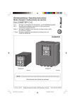
Betriebsanleitung/Operating Instructions Schalttafeleinbaugeräte Panel Mounting Devices > 8003/1 Betriebsanleitung Schalttafeleinbaugeräte > 8003/1 Inhaltsverzeichnis 1 Inhaltsverzeichnis 1 2 3 4 5 6 7 8 9 10 11 12 13 14 15 2 Inhaltsverzeichnis ..................................................................................................2 Allgemeine Angaben .............................................................................................2 Verwendung ..........................................................................................................2 Allgemeine Sicherheitshinweise ............................................................................3 Normenkonformität ................................................................................................3 Transport und Lagerung ........................................................................................3 Technische Daten .................................................................................................4 Maßangaben .........................................................................................................5 Montage und Demontage ......................................................................................6 Installation .............................................................................................................7 Inbetriebnahme .....................................................................................................9 Instandhaltung, Wartung und Störbeseitigung ......................................................9 Zubehör und Ersatzteile .....................................................................................10 Entsorgung ..........................................................................................................11 EG-Konformitätserklärung ...................................................................................12 Allgemeine Angaben 2.1 Hersteller R. STAHL Schaltgeräte GmbH Am Bahnhof 30 74638 Waldenburg Germany Tel.: Fax: Internet: +49 7942 943-0 +49 7942 943-4333 www.stahl-ex.com 2.2 Angaben zur Betriebsanleitung ID-NR.: Publikationsnummer: Änderungen vorbehalten. 3 127303 / 8003607300 2011-05-04·BA00·III·de·04 Verwendung Die Schaltafeleinbaugeräte schalten Last-, Steuer- und Signalstromkreise und sind zugelassen für den Einsatz in explosionsgefährdeten Bereichen der Zonen 1 und 2. Die Typen 8003/1.1 und 8003/1.3 sind komplett bescheinigte explosionsgeschützte Betriebsmittel, geeignet zum Einbau in Gehäusewände, Deckel elektrischer Geräte und Schalttafeln oder Steuerschränke. Die Typen 8003/1.2 sind unvollständige explosionsgeschützte elektrische Betriebsmittel und müssen in ein Gehäuse der Zündschutzart „Erhöhte Sicherheit“ nach IEC/EN 60079-7 eingebaut werden. 2 Schalttafeleinbaugeräte 8003/1 127303 / 8003607300 2011-05-04·BA00·III·de·04 Allgemeine Sicherheitshinweise Die Geräte sind für die Einlochbefestigung D30 nach EN 50007, in Kombination mit den Betätigungsvorsätzen Typ 8602/2, ausgelegt. Die Standard-Schalter und StandardSchlüsselschalter sind in allen Stellungen „rastend“. Bei den Standard-Schlüsseltastern kann der Schlüssel in allen Stellungen abgezogen werden. Die Schalter können mittels Codierteilen auf die Funktion „tastend“ bzw. „rastend, Schlüssel nicht abziehbar“ umgebaut werden. 4 Allgemeine Sicherheitshinweise Die Geräte sind nur für den zugelassenen Einsatzzweck zu verwenden. Fehlerhafter oder unzulässiger Einsatz sowie das Nichtbeachten der Hinweise dieser Betriebsanleitung schließen eine Gewährleistung unsererseits aus. Umbauten und Veränderungen am Gerät, die den Explosionsschutz beeinträchtigen, sind nicht gestattet. Das Gerät darf nur im unbeschädigten und sauberen Zustand betrieben werden. WARNUNG Installation, Instandhaltung, Wartung und Störbeseitigung darf nur von dazu befugtem und entsprechend geschultem Personal durchgeführt werden. Bei Installation und Betrieb ist Folgendes zu beachten: Beschädigungen können den Explosionsschutz aufheben Nationale und örtliche Sicherheitsvorschriften Nationale und örtliche Unfallverhütungsvorschriften Nationale und örtliche Montage- und Errichtungsvorschriften (z.B. IEC/EN 60079-14) Allgemein anerkannte Regeln der Technik Sicherheitshinweise dieser Betriebsanleitung Kennwerte und Bemessungsbetriebsbedingungen der Typ- und Datenschilder Zusätzliche Hinweisschilder auf dem Gerät Typ 8003/1.2: beim Einbau in Gehäuse der Zündschutzart „Erhöhte Sicherheit“ sind die Bedingungen der IEC/EN 60079-0 und IEC/EN 60079-7 zu berücksichtigen Typ 8003/1.1 und 8003/1.3: die Rückseite der Geräte muss gegen mechanische Beschädigung geschützt werden 5 Normenkonformität Die relevanten Normen sind in der EG-Konformitätserklärung bzw. IECEx Certificate of Conformity aufgelistet. Diese Dokumente können auf unserer Homepage www.stahl-ex.com im Download-Bereich abgerufen werden. 6 Transport und Lagerung Transport und Lagerung sind nur in Originalverpackung gestattet. 127303 / 8003607300 2011-05-04·BA00·III·de·04 Schalttafeleinbaugeräte 8003/1 3 Technische Daten 7 Technische Daten Explosionsschutz Gasexplosionsschutz 8003/1.1 8003/1.2 8003/1.3 E II 2 G Ex d e IIC T6 E II 2 G Ex d e IIC E II 2 G Ex d e IIC T6 Gasexplosionsschutz (IECEx) 8003/1.1 8003/1.2 8003/1.3 Ex d e IIC T6 Ex d e IIC Ex d e IIC T6 Staubexplosionsschutz 8003/1.1 8003/1.3 E II 2 D Ex tD A21 IP65 T80°C Staubexplosionsschutz (IECEx) 8003/1.1 8003/1.3 Ex tD A21 IP 65 T80°C Bescheinigungen 8003/1.1 8003/1.2 8003/1.3 PTB 02 ATEX 1057 X PTB 02 ATEX 1080 U PTB 02 ATEX 1057 X IECEx Zulassung 8003/1.1 8003/1.2 8003/1.3 IECEx PTB 06.0065X IECEx PTB 06.0066U IECEx PTB 06.0065X Umgebungstemperatur - 20 ... + 60 °C - 55 ... + 60 °C bei Ausführungen mit Silikondichtung Bemessungsbetriebsspannung max. 550 V Bemessungsbetriebsstrom max. 6 A Schaltbild 10503E00 09792E00 8003/11. Mindestspannung* 12 V AC / DC Mindeststrom* 50 mA 8003/12. 09791E00 09790E00 8003/13. 8003/14. * Richtwerte abhängig von den Einsatzbedingungen Schaltleistung Bemessungsbetriebsgrenzwerte bezogen auf die Gebrauchskategorie AC-15 AC-12 DC-13 DC-13 500 V max. 6 A max. 1250 VA 500 V max. 6 A max. 3000 VA 60 V max. 6 A 110 V max. 1 A max. 110 W Material Gehäuse Polyamid Kontaktmaterial Standard Silber-Nickel Sonder Silber-Nickel, vergoldet Lebensdauer Kontaktelement Schutzart 106 Schaltspiele IP65 (frontseitig IP66) Schutzgrad gemäß IEC/EN 60529 4 Leitungseinführung Typ 8003/1.1: Anschlussquerschnitt 8003/1.1: 0,75 ... 1,5 mm2 8003/1.2: 0,5 ... 2,5 mm2 8003/1.3: 4 x 1 mm2, Anschlussleitung Gewicht 0,0825 kg (ohne Anschlussleitung und Vorsatz) Schalttafeleinbaugeräte 8003/1 M16 x 1,5 (d 4 - 9 mm) 127303 / 8003607300 2011-05-04·BA00·III·de·04 Maßangaben 8 Maßangaben Maßzeichnungen (alle Maße in mm) - Änderungen vorbehalten 52 Ø 38 Ø 72 Ø 55 36 40 Ø 38 40 Ø 04422E00 8003/... -010, -012 Pilzsperrtaster 04835E00 8003/...-003 Pilzdrucktaster 04424E00 8003/...-015 Pilzsperrtaster 04429E00 04426E00 8003/1.1-001 Drucktaster mit Anschlussraum 8003/...-006, -009 Pilzschlüsseltaster 10546E00 8003/...-008 Schlüsselschalter 42 04428E00 8003/...-005 Wahllschalter 42 04488E00 Bohrbild Aneinanderreihung mehrerer Schalttafeleinbaugeräte d38 mm 42 08747E00 Einbaurastermaß für NOT-AUS-Taster (8003/...-009, -010, -015) 127303 / 8003607300 2011-05-04·BA00·III·de·04 60 51 46 17 40 Ø 30,5 3,5 08746E00 Einbaurastermaß mit / ohne Zusatz-Bezeichnungsschild Schalttafeleinbaugeräte 8003/1 5 Montage und Demontage 9 Montage und Demontage Die Schalttafeleinbaugeräte eignen sich für den Einbau in Gehäusewände oder Schalttafeln mit einer Wandstärke von 1,0 ... 6,5 mm. Der Durchmesser der Montagebohrung beträgt 30,5 mm. Einlochmontage (6) (2) (5) (8) (7) (4) (1) Betätigungsvorsatz (2) Einbauwand (3) Schalttafeleinbaugerät (4) Dichtung (5) Rippe (6) Nut (7) Kabelverschraubung (8) Gewindemutter (3) (1) 11610E00 Bei der Montage ist zu beachten: X Das Schalttafeleinbaugerät (3) darf nicht verkanten. X Das Schalttafeleinbaugerät (3) und der Betätigungsvorsatz (1) müssen fest in der Einbauwand (2) sitzen. X Die Dichtung (4) muss exakt eingesetzt sein. X Anzugsdrehmoment der Gewindemutter: 2,5 Nm. Montage: Den Betätigungsvorsatz (1) in die Einbauwand (2) stecken und arretieren. Das Schalttafeleinbaugerät (3) von der Rückseite aus, auf den Betätigungsvorsatz (1) stecken Mit der Gewindemutter (8) den Betätigungsvorsatz (1) gegen die Einbauwand (2) festziehen. WARNUNG Folgende Montageanweisungen sind bei den Schlüsselschaltern 8003/1..-008 und den Drehgriffen 8003/1..-726 und 8003/1..-727 unbedingt einzuhalten: X Die Rippe (5) muss in der Nut (6) der Einbauwand (2) sitzen. X Das Schalttafeleinbaugerät (3) muss so aufgesteckt werden, dass die Kabelverschraubung (7) um 180° zur Nut gedreht ist (siehe Bild Einlochmontage: Nut oben, Kabelverschraubung nach unten). 6 Schalttafeleinbaugeräte 8003/1 127303 / 8003607300 2011-05-04·BA00·III·de·04 Installation 10 Installation 10.1 Elektrischer Anschluss 8003/1.1: Ausführungen mit Federzugklemme und Anschlussraum 8003/1.2: Ausführungen mit Federzugklemme 8003/1.3: Ausführungen mit Anschlussleitung Der Leiteranschluss ist mit besonderer Sorgfalt durchzuführen. Der Leiteranschluss muss bis an die Klemme heranreichen. Beim Abisolieren darf der Leiter nicht beschädigt (eingekerbt) werden. Durch eine geeignete Auswahl der verwendeten Leitungen sowie die Art der Verlegung ist sicherzustellen, dass die maximal zulässigen Leitertemperaturen nicht überschritten werden. Die Angaben im Kapitel „Technische Daten“ sind zu beachten. WARNUNG Bei Anschluss innerhalb eines explosionsgefährdeten Bereiches muss die Leiterverbindung in einer der Zone entsprechenden Zündschutzart erfolgen. Anschlussquerschnitte: 8003/1.1: 0,75 ... 1,5 mm2 8003/1.2: 0,5 ... 2,5 mm2 8003/1.3: 4 x 1,0 mm2 11611T00 Verwendbare Kupferleiter: ein-, mehr-, fein- oder feinstdrähtig 10.2 Ausführungen mit Federzugklemme beim Typ 8003/1.1 Leitungseinführung Es sind ausschließlich Leitungen mit einem Außendurchmesser von 5 ... 9 mm zu verwenden. 11612T00 Leitung von hinten in die Kabelverschraubung (1) einführen. Leitung in den Anschlussraumdeckel schieben, bis eine ausreichende Länge zur Leitungsvorbereitung als freies Ende auf der anderen Seite zur Verfügung steht (2). 127303 / 8003607300 2011-05-04·BA00·III·de·04 Schalttafeleinbaugeräte 8003/1 7 Installation Leitungsvorbereitung beim Typ 8003/1.1 11613T00 Leiter 40 mm abmanteln. Adern 6 mm abmanteln. WARNUNG Zur Sicherstellung der erforderlichen Luft- und Kriechstrecke muss die vorgegebene Abisolierlänge der Adern (6 mm) genau eingehalten werden. Leiteranschluss bei den Typen 8003/1.1 und 8003/1.2 11614T00 (1) Schnittdarstellung Federzugklemme. Federzugklemme (2) mit einem Schlitzschraubendreher (0,6x3,5 mm Form A, DIN 5264/ISO 2380-1) öffnen. Die Schraubendreherschneide hält die Federzugklemme geöffnet, so dass der Leiter eingeführt werden kann. Vorbereiteten Leiter (3) einführen. Schraubendreher entfernen, der Leiter ist sicher geklemmt (4). Verschließen des Anschlussraums beim Typ 8003/1.1 Anschlussraum geöffnet 11615T00 Anschlussraumdeckel aufschieben 11616T00 11617T00 Anschlussdeckel auf Klemmenträger (1) schieben bis dieser einrastet. Leitung in Richtung Anschlussraumdeckel (2) schieben. Mutter der Verschraubung mit einem Drehmoment von ca. 1,3 Nm anziehen. Der Anschlussraum ist dicht verschlossen. WARNUNG Kabel oder Leitungen müssen fest installiert werden. Eine Zugentlastung ist vorzusehen. 8 Schalttafeleinbaugeräte 8003/1 127303 / 8003607300 2011-05-04·BA00·III·de·04 Inbetriebnahme Öffnen des Anschlussraums beim Typ 8003/1.1 11618T00 Anschlussraum nur mit geeignetem Werkzeug öffnen, z.B. Schlitzschraubendreher 0,6 x 3,5. Schraubendreher an einer Lasche ansetzen und um 90° drehen. Anschlussraumdeckel etwas zurückziehen und in dieser Stellung halten. Schraubendreher an der zweiten Lasche ansetzen und um 90° drehen. Anschlussraumdeckel abnehmen. 11 Inbetriebnahme Vor Inbetriebnahme Sicherstellen, dass das Gerät nicht beschädigt ist. Sicherstellen, dass das Gerät vorschriftsmäßig installiert ist. Fremdkörper aus dem Gerät entfernen. Kabelverschraubungen auf festen Sitz prüfen. Schrauben und Muttern auf festen Sitz prüfen. Anzugsdrehmomente kontrollieren. 12 Instandhaltung, Wartung und Störbeseitigung WARNUNG Nicht unter Spannung öffnen! Bei der Wartung sind folgende Punkte zu überprüfen: X Einhaltung der zulässigen Temperaturen (gemäß IEC/EN 60079) X Beschädigungen am Gehäuse und an den Dichtungen X Fester Sitz der Leitungen 127303 / 8003607300 2011-05-04·BA00·III·de·04 Schalttafeleinbaugeräte 8003/1 9 Zubehör und Ersatzteile 13 Zubehör und Ersatzteile WARNUNG Es ist nur Original-Zubehör sowie Original-Ersatzteile der Fa. R. STAHL zu verwenden. Bezeichnung Abbildung Ersatzschlüssel 10545E00 Verschlussteil Beschreibung Art.Nr. Gewicht kg für alle Schlüsseltaster / Schlüsselschalter Standardschließung MS1 Sonderschließung MS2 ... MS20 (als Text angeben) 107109 107110 0,008 0,008 zum Verschließen unbenutzter Deckelbohrungen d 30,5 mm 155329 0,016 Schildträger, Größe 1, ohne Einlegeschild Beschriftung: 1-zeilig Schildträger, Größe 2, ohne Einlegeschild Beschriftung: 1- oder 2-zeilig Schildträger, Größe 3, ohne Einlegeschild Beschriftung: 1-, 2- oder 3-zeilig für Betätigungsvorsätze einbaubar in Bohrungen d 30,5 mm 155632 0,001 155687 0,002 155844 0,002 155432 155373 155403 130391 130524 155525 0,001 0,001 0,001 0,000 0,001 0,002 0,023 05647E00 ZusatzBezeichnungsschild 05543E00 Einlegeschilder: ohne Beschriftung mit Beschriftung; Texte im Klartext angeben: HAND - 0 - AUTO OFF - ¸ - ON 0-I I - II Umbausatz für Schlüsselschalter Unterlegschild, gelb 05024E00 Betätigungsvorsatz I - 0 - II 0 - I - II 0 - Betrieb - I 0-¸-I Umbausatz Codierteile für Schlüsselschalter Typ 8003/...-008-. Codierteil, 1 x rot, 1 x gelb Codierteil, 2 x gelb Codierteil, 1 x grün, 1 x rot für Taster mit NOT-AUS-Funktion d 38 mm d 55 mm für Drucktaster 8003/...-001 05733E00 für Pilzdrucktaster d 38 mm, schwarz 8003/...-003 155526 0,028 für Pilzsperrtaster d 38 mm, rot (NOT-AUS) 8003/...-010 155531 0,030 für Pilzsperrtaster d 38 mm, schwarz 8003/...-012 155541 0,030 für Pilzsperrtaster d 55 mm, rot (NOT-AUS) 8003/...-015 155532 0,033 für Pilzschlüsseltaster d 38 mm, rot (NOT-AUS) 8003/...-009 155530 0,062 für Schlüsselschalter mit 2 Schaltstellungen 8003/...-008-2 155528 0,049 für Schlüsselschalter mit 3 Schaltstellungen 8003/...-008-3 155529 0,049 für Wahlschalter 8003/...-005 155527 0,030 05538E00 05536E00 05533E00 05537E00 05734E00 05535E00 10 Schalttafeleinbaugeräte 8003/1 127303 / 8003607300 2011-05-04·BA00·III·de·04 Entsorgung Bezeichnung Abbildung Einlegeschild für Drucktaster und Wahlschalter 05753E00 Beschreibung Art.Nr. Gewicht kg Farbe Text blau Leerschild (Text angeben) 155910 0,001 gelb Leerschild (Text angeben) 155913 0,001 rot Leerschild (Text angeben) 155896 0,001 grün Leerschild (Text angeben) 155900 0,001 weiß Leerschild (Text angeben) 155907 0,001 schwarz Leerschild (Text angeben) 155904 0,001 blau Leerschild 155911 0,001 gelb Leerschild 155914 0,001 rot Leerschild 155897 0,001 grün Leerschild 155901 0,001 weiß Leerschild 155908 0,001 schwarz Leerschild 155905 0,001 schwarz I 155846 0,001 grün I 155689 0,001 weiß I 155892 0,001 schwarz II 155854 0,001 grün II 155706 0,001 rot 0 155596 0,001 155783 0,001 155771 0,001 schwarz 0 schwarz I rot ¨ 155567 0,001 schwarz ¢ 155736 0,001 schwarz ¤ 155749 0,001 schwarz ¦ 155761 0,001 schwarz CLOSE 155878 0,001 schwarz Zu 155874 0,001 schwarz Open 155868 0,001 schwarz EIN 155862 0,001 rot OFF 155654 0,001 rot Aus 155634 0,001 schwarz Aus 155806 0,001 rot STOP 155615 0,001 schwarz STOP 155795 0,001 grün START 155721 0,001 weiß START 155889 0,001 blau RESET 155894 0,001 grün ON 155671 0,001 schwarz Auf 155883 0,001 schwarz Ab 155886 0,001 schwarz Links 155827 0,001 schwarz Rechts 155837 0,001 0 14 Entsorgung Die nationalen Vorschriften zur Abfallbeseitigung sind zu beachten. 127303 / 8003607300 2011-05-04·BA00·III·de·04 Schalttafeleinbaugeräte 8003/1 11 EG-Konformitätserklärung 15 EG-Konformitätserklärung 12 Schalttafeleinbaugeräte 8003/1 127303 / 8003607300 2011-05-04·BA00·III·de·04 EG-Konformitätserklärung 127303 / 8003607300 2011-05-04·BA00·III·de·04 Schalttafeleinbaugeräte 8003/1 13 127303 / 8003607300 2011-05-04·BA00·III·de·04 Operating Instructions Panel Mounting Devices > 8003/1 Contents 1 Contents 1 2 3 4 5 6 7 8 9 10 11 12 13 14 15 16 2 Contents ................................................................................................................2 General Information ...............................................................................................2 Intended Use .........................................................................................................2 General Safety Instructions ...................................................................................3 Conformity to Standards ........................................................................................3 Transport and Storage ..........................................................................................3 Technical Data ......................................................................................................4 Dimensions ............................................................................................................5 Assembling and Dismantling .................................................................................6 Installation .............................................................................................................7 Putting into Service ...............................................................................................9 Maintenance, Overhaul and Repair .......................................................................9 Accessories and Spare Parts ..............................................................................10 Disposal ...............................................................................................................11 EC Declaration Of Conformity .............................................................................12 IOM sheet ............................................................................................................14 General Information 2.1 Manufacturer R. STAHL Schaltgeräte GmbH Am Bahnhof 30 74638 Waldenburg Germany Tel: +49 7942 943-0 Fax: +49 7942 943-4333 Internet: www.stahl-ex.com 2.2 Operating Instructions Information ID-No.: Publication Code: Subject to alterations. 3 127303 / 8003607300 2011-05-04·BA00·III·en·04 Intended Use The panel mounting devices switch load, control and signal circuits and are certified for use in hazardous areas of Zones 1 and 2. Types 8003/1.1 und 8003/1.3 are complete certified explosion-protected equipment suitable for installation in enclosure walls, covers of electric devices, switch panels or control cabinets. Types 8003/1.2 are incomplete, explosion-protected electrical equipment suitable for installation in enclosures of type of protection "increased safety" according to IEC/EN 60079-7. 2 Panel Mounting Devices 8003/1 127303 / 8003607300 2011-05-04·BA00·III·en·04 General Safety Instructions The devices are designed for single-hole mounting D 30 to EN 50007 in combination with actuators Type 8602/2. The standard switches and standard key-operated switches are "latching" in all positions. In the standard key-operated buttons, the key is withdrawable in all positions. Due to integration of coding elements, the switches can be converted to the “spring return“ or “latching, key non-withdrawable“ functions. 4 General Safety Instructions The devices must be used only for the permitted purpose. Incorrect or impermissible use or non-compliance with these instructions invalidates our warranty provision. Any alterations and modifications to the device impairing its explosion protection are not permitted. Use the device only if it is undamaged and clean. WARNING Installation, maintenance, overhaul and repair may only be carried out by appropriately authorised and trained personnel. Observe the following information during installation and operation: Any damage can invalidate the explosion protection National and local safety regulations National and local accident prevention regulations National and local assembly and installation regulations (e.g. IEC/EN 60079-14) Generally recognized technical regulations Safety instructions in these operating instructions Characteristic values and rated operating conditions on the rating and data plates Additional instruction plates fixed directly to the device Type 8003/1.2: when installed in enclosures of type of protection “increased safety“, the conditions given in IEC/EN 60079-0 and IEC/EN 60079-7 must be observed Types 8003/1.1 and 8003/1.3: the backs of the devices must be protected against mechanical damage 5 Conformity to Standards The relevant standards are listed in the EC Declaration of Conformity or IECEx Certificate of Conformity. These documents are available for download in the download area on the internet page www.stahl-ex.com. 6 Transport and Storage Transport and storage are only permitted in the original packing. 127303 / 8003607300 2011-05-04·BA00·III·en·04 Panel Mounting Devices 8003/1 3 Technical Data 7 Technical Data Explosion protection Gas explosion protection 8003/1.1 8003/1.2 8003/1.3 E II 2 G Ex d e IIC T6 E II 2 G Ex d e IIC E II 2 G Ex d e IIC T6 Gas explosion protection (IECEx) 8003/1.1 8003/1.2 8003/1.3 Ex d e IIC T6 Ex d e IIC Ex d e IIC T6 Dust explosion protection 8003/1.1 8003/1.3 E II 2 D Ex tD A21 IP65 T80°C Dust explosion protection (IECEx) 8003/1.1 8003/1.3 Ex tD A21 IP 65 T80°C Certificates 8003/1.1 8003/1.2 8003/1.3 PTB 02 ATEX 1057 X PTB 02 ATEX 1080 U PTB 02 ATEX 1057 X IECEx certification 8003/1.1 8003/1.2 8003/1.3 IECEx PTB 06.0065X IECEx PTB 06.0066U IECEx PTB 06.0065X Ambient temperature - 20 ... + 60 °C - 55 ... + 60 °C for versions with silicone seal Rated operational voltage max. 550 V Rated operational current max. 6 A Schematic 10503E00 09792E00 8003/11. 09791E00 8003/12. 8003/13. Min. voltage* 12 V AC / DC Min. current* 50 mA Switching capacity Rated operating characteristics according to utilisation category 09790E00 8003/14. * Typical values dependent on conditions of use AC-15 AC-12 DC-13 DC-13 500 V max. 6 A max. 1250 VA 500 V max. 6 A max. 3000 VA 60 V max. 6 A 110 V max. 1 A max. 110 W Material Enclosure Polyamide Contact material Standard Silver-nickel Special Silver-nickel, gold-plated Service life Contact element Degree of protection 106 operating cycles IP65 (front side IP66) Degree of protection acc. to IEC/EN 60529 4 Cable entry Type 8003/1.1: Connection cross-section 0.75 ... 1.5 mm2 Weight 0.0825 kg (without connecting cable and actuator) Panel Mounting Devices 8003/1 M16 x 1.5 (d 4 - 9 mm) 127303 / 8003607300 2011-05-04·BA00·III·en·04 Dimensions 8 Dimensions Dimensional Drawings (All Dimensions in mm) - Subject to Alterations 52 Ø 38 Ø 72 Ø 55 36 40 Ø 38 40 Ø 04422E00 8003/... -010, -012 Mushroom stay-put button 04835E00 8003/...-003 Mushroom pushbutton 04424E00 8003/...-015 Mushroom stay-put button 04429E00 04426E00 8003/1.1-001 Pushbutton with connection chamber 8003/...-006, -009 Mushroom stay-put button with key lock 10546E00 8003/...-008 Key-operated switch 42 04428E00 8003/...-005 Selector switch 42 04488E00 Cut-out for aligning several devices ø38 mm in a panel 42 08747E00 Cut-out for EM-STOP button (8003/...-009, -010, -015) 127303 / 8003607300 2011-05-04·BA00·III·en·04 60 51 46 17 40 Ø 30,5 3,5 08746E00 Cut-out with / without additional identification plate Panel Mounting Devices 8003/1 5 Assembling and Dismantling 9 Assembling and Dismantling The panel mounting devices are suitable for installation in enclosure walls or switch panels with a wall thickness of 1.0 ... 6.5 mm. The mounting hole diameter is 30.5 mm. Single hole mounting (1) (6) (2) (5) (8) (7) (4) Actuator (2) Installation wall (3) Panel mounting device (4) Seal (5) Rib (6) Groove (7) Cable gland (8) Threaded nut (3) (1) 11610E00 When assembling, please note that: X The panel mounting device (3) may not be set at an angle! X The panel mounting device (3) and the actuator (1) must be firmly attached in the installation wall (2). X The seal (4) must be precisely inserted. X Tightening torque of the threaded nut: 2.5 Nm. Assembling: Push the actuator (1) into the installation wall (2) and lock it into position. Push the panel-mounting fixture (3) onto the actuator (1) from the back of the installation wall. Tighten the actuator (1) against the installation wall (2) to which it is fitted by turning the threaded nut (8). WARNING For key-operated switches 8003/1..-008 and rotary actuators 8003/1..-726 and 8003/1..-727 the following mounting instructions must be observed: X The rib (5) must sit properly in the groove (6) in the installation wall (2). X The panel-mounting fixture (3) must be inserted in such a way that the cable gland (7) is rotated by 180°, relative to the groove (see single hole mounting figure: groove at the top, cable gland downward 6 Panel Mounting Devices 8003/1 127303 / 8003607300 2011-05-04·BA00·III·en·04 Installation 10 Installation 10.1 Electrical Connection 8003/1.1: versions with spring clamp terminal and connection chamber 8003/1.2: versions with spring clamp terminal 8003/1.3: versions with connecting cable The conductor must be carefully connected. The conductor connection must reach to the terminal. When stripping the insulation, the conductor must not be damaged (nicked). To ensure that the maximum permissible conductor temperatures are not exceeded, select suitable cables and means of running them. The information given in chapter "Technical Data" must be observed. WARNING Please note that when connecting the device within a hazardous area, the connection must be made in a type of protection corresponding to the zone. Connection cross-sections: 8003/1.1: 0.75 ... 1.5 mm2 8003/1.2: 0.5 ... 2.5 mm2 8003/1.3: 4 x 1.0 mm2 11611T00 Usable copper conductors: single wire, stranded, finely or very finely stranded 10.2 Versions with Spring Clamp Terminal for Type 8003/1.1 Cable gland Use only cables that have an outer diameter of 5 ... 9 mm. 11612T00 Push the cable into the cable gland (1) from behind. Push the cable into the connection chamber cover until there is a sufficient length left free on the other side to enable connections to be prepared (2). Preparing the cable for type 8003/3.1 11613T00 Strip 40 mm of the insulation of the conductor. Strip 6 mm of the insulation of the wires. WARNING To ensure the required clearance and creepage distance, the specified stripping length of the wires (6 mm) must be precisely complied with. 127303 / 8003607300 2011-05-04·BA00·III·en·04 Panel Mounting Devices 8003/1 7 Installation Conductor connection for types 8003/1.1 and 8003/1.2 11614T00 (1) Sectional view of the spring clamp terminal. Open the spring clamp terminal (2) using a slotted screwdriver (0.6x3.5 mm form A, DIN 5264/ISO 2380-1). The screwdriver blade holds the spring clamp terminal open, thus enabling the conductor to be introduced. Introduce the prepared conductor (3). Remove the screwdriver, thus securely clamping the conductor (4). Closing the connection chamber of type 8003/1.1 Connection chamber open 11615T00 Opening the connection chamber cover 11616T00 11617T00 Push the connection cover onto the terminal support (1) until it snaps into place. Push the cable toward the connection chamber cover (2). Tighten the gland nut to a torque of approx. 1.3 Nm. The connection chamber is now tightly sealed. WARNING Cables must be fixed in position. A strain relief must be provided. 8 Panel Mounting Devices 8003/1 127303 / 8003607300 2011-05-04·BA00·III·en·04 Putting into Service Opening the connection chamber of type 8003/1.1 11618T00 Open the connection chamber only if you have a suitable tool, for example a slotted screwdriver 0.6 x 3.5. Position the screwdriver against one of the latching tabs and turn it by 90°. Slightly pull back the connection chamber cover and hold it in this position. Position the screwdriver against the second latching tab and turn it by 90°. Remove the connection chamber cover. 11 Putting into Service Before putting into service Make sure that the device is not damaged. Make sure that the device has been installed correctly. Remove any foreign objects from the device. Check whether the cable glands have been tightened properly. Check whether screws and nuts have been tightened properly. Check the tightening torques. 12 Maintenance, Overhaul and Repair WARNING Do not open when live! The following details must be checked during maintenance: X Compliance with the permitted temperatures (acc. to IEC/EN 60079) X Damage to the enclosure and seals X Cables are held securely in place 127303 / 8003607300 2011-05-04·BA00·III·en·04 Panel Mounting Devices 8003/1 9 Accessories and Spare Parts 13 Accessories and Spare Parts WARNING Use only original R. STAHL accessories and spare parts. Designation Illustration Spare key 10545E00 Closing part Description Art. no. Weight kg for all key-operated buttons / key-operated switches Standard locking MS1 Special locking MS2 ... MS20 (specify as text) 107109 107110 0.008 0.008 for closing of unused mounting holes d 30.5 mm 155329 0.016 Label mount, size 1, without symbol label Text: 1 line Label mount, size 2, without symbol label Text: 1 or 2 lines Label mount, size 3, without symbol label Text: 1, 2 or 3 lines for actuators to fit d 30.5 mm holes 155632 0.001 155687 0.002 155844 0.002 155432 155373 155403 130391 130524 155525 0.001 0.001 0.001 0.000 0.001 0.002 0.023 05647E00 Additional identification plate 05543E00 Symbol labels: without text with text; please specify text: HAND - 0 - AUTO OFF - ¸ - ON 0-I I - II Coding kit for key-operated switch Support plate, yellow 05024E00 Actuator I - 0 - II 0 - I - II 0 - Betrieb - I 0-¸-I Coding kit for key-operated switches Types 8003/...-008-. Coding element, 1 x red, 1 x yellow Coding element, 2 x yellow Coding element, 1 x green, 1 x red for buttons with EM-STOP function d 38 mm d 55 mm for pushbuttons 8003/...-001 05733E00 for mushroom pushbuttons d 38 mm, black 8003/...-003 155526 0.028 for mushroom stay-put buttons d 38 mm, red (EM-STOP) 8003/...-010 155531 0.030 for mushroom stay-put buttons d 38 mm, black 8003/...-012 155541 0.030 for mushroom stay-put buttons d 55 mm, red (EM-STOP) 8003/...-015 155532 0.033 for mushroom stay-put buttons with key lock d 38 mm, red (EM-STOP) 8003/...-009 155530 0.062 for key-operated switches with 2 switching positions 8003/...-008-2 155528 0.049 for key-operated switches with 3 switching positions 8003/...-008-3 155529 0.049 for selector switches 8003/...-005 155527 0.030 05538E00 05536E00 05533E00 05537E00 05734E00 05535E00 10 Panel Mounting Devices 8003/1 127303 / 8003607300 2011-05-04·BA00·III·en·04 Disposal Designation Illustration Symbol label for pushbutton and selector switch 05753E00 Description Art. no. Weight kg Colour Text blue Plain label (specify text) 155910 0.001 yellow Plain label (specify text) 155913 0.001 red Plain label (specify text) 155896 0.001 green Plain label (specify text) 155900 0.001 white Plain label (specify text) 155907 0.001 black Plain label (specify text) 155904 0.001 blue Plain label 155911 0.001 yellow Plain label 155914 0.001 red Plain label 155897 0.001 green Plain label 155901 0.001 white Plain label 155908 0.001 black Plain label 155905 0.001 black I 155846 0.001 green I 155689 0.001 white I 155892 0.001 black II 155854 0.001 green II 155706 0.001 red 0 155596 0.001 black 0 155783 0.001 black I0 155771 0.001 red ¨ 155567 0.001 black ¢ 155736 0.001 black ¤ 155749 0.001 black ¦ 155761 0.001 black CLOSE 155878 0.001 black Zu 155874 0.001 black Open 155868 0.001 black EIN 155862 0.001 red OFF 155654 0.001 red Aus 155634 0.001 black Aus 155806 0.001 red STOP 155615 0.001 black STOP 155795 0.001 green START 155721 0.001 white START 155889 0.001 blue RESET 155894 0.001 green ON 155671 0.001 black Auf 155883 0.001 black Ab 155886 0.001 black Links 155827 0.001 black Rechts 155837 0.001 14 Disposal The national waste disposal regulations have to be observed. 127303 / 8003607300 2011-05-04·BA00·III·en·04 Panel Mounting Devices 8003/1 11 EC Declaration Of Conformity 15 EC Declaration Of Conformity 12 Panel Mounting Devices 8003/1 127303 / 8003607300 2011-05-04·BA00·III·en·04 EC Declaration Of Conformity 127303 / 8003607300 2011-05-04·BA00·III·en·04 Panel Mounting Devices 8003/1 13 IOM sheet 16 IOM sheet R. STAHL, INC. INSTALLATION OPERATION & MAINTENANCE SHEET 9001 Knight Road Houston, TX 77054 Tel: 800-782-4357 FAX: 713-792-9301 E-mail: [email protected] Website: www.rstahl.com Series 8003/1 Panel Mounted Pushbuttons and Selector Switches Please read this entire document before beginning any work. 1. Safety Instructions 3. Installation of devices 8003/1•• Installation and maintenance of these devices should only be performed by qualified personnel in accordance with the National Electrical Code (NEC) (NFPA 70) or the Canadian Electrical Code (CEC) and any applicable code regulations. CAUTION: These explosion protected electrical devices are typically installed in an electrical panel or enclosure. The types of enclosures needed for the different area classifications indicated in the left column of the table below, are stated in the middle or right column. Enclosure Type Rating For Installation • Disconnect power supply before installing or servicing these devices. • Operate only undamaged devices with observations of the operating parameters in Section 2. Devices with Cap 8003/1•1 or with Cap & Lead 8003/1•3 Class I, Zone 1 Enclosure Type➀ 1, 2, 3, 3R, 4, 4X, 12, 13 Class I, Division 2 Groups A, B, C, & D 2. Technical Data Please refer to the technical data on the device. Area Classification of Use Devices with Cage Clamps 8003/1•2 (without Cap) Enclosure AEx e or Ex e Enclosure Type 1, 2 ,3, 3R, 4, 4X, 12, 13 ➀Terminate leads in AEx e Terminal Box 2.1 Certifications File No. E182378 Class I, Zone 1, AEx de IIC T6 Class I, Zone 1, Ex de IIC T6 Class I, Div. 2, Groups A,B,C & D 3.1 Punching Knock-outs • Punch 1.2" diameter knock-outs (30.5mm) into the panel. These devices can be mounted into walls between 0.04 - 0.25" (1.0 … 6.5mm) • Observe the clearances. See information on the device 3.2 Removing the actuator from the contact block: 2.2 Ambient temperature range: -30°C to +55°C. • Turn the retainer nut counter-clockwise as far as it will go. • Pull off the actuator. 2.3 Storage temperature range: -55°C to +100°C. 2.4 Environmental protection type: 3, 4; 4x IP66/IP20 at terminals depending on enclosure (see section 3). I.D.1.2” (30.5mm) 2.5 General electrical data: 2.5.1 Cage clamp terminal capacity: 2x 18 AWG to 2x 12 AWG. 2.5.2 Switching capacity: AC, 600V, 10A max. (A600). 2.5.3 Lowest Energy: 12V AC/DC, 50mA. 2.5.4 Contact Arrangements: See nameplate on the .66” (17mm) .13” (3.5mm) 1.65” (42mm) When installing devices with terminal cap, type 8003/1•1, skip section 4. device. Contact numbers on the device are embossed next to the terminal openings. 80 036 08 30 0 14 Panel Mounting Devices 8003/1 1/4 December 13, 2006 127303 / 8003607300 2011-05-04·BA00·III·en·04 IOM sheet R. STAHL, INC. INSTALLATION OPERATION & MAINTENANCE SHEET 9001 Knight Road Houston, TX 77054 Tel: 800-782-4357 FAX: 713-792-9301 E-mail: [email protected] Website: www.rstahl.com 4. Installation of devices 8003/1•2 into the panel. 5. Installation of devices 8003/1•1 into the panel. 4.1 Dimensions 5.1 Dimensions • Push the actuator from the front through the panel knock-out making sure the gasket is seated flat against the panel and lock it in position. • Align the contact block to the three tabs of the actuator part and snap them together. 5.2 To open the terminal cap use a screwdriver with blade of 0.6 x 3.5 mm. • Tighten the retainer nut against the panel. • Position the screwdriver against one of the locking tabs. • Turn it 90°. 4.2 Cage clamp terminals • Pull the cap back a little and hold it in this position. • Capacity 2 x 18 to 2 x 12 AWG. 4.3 Conductor connection to cage- • Position the screwdriver against the second locking tab. clamp terminals. 1. Cut-away, showing cage-clamp terminals with capacity of 2 x 18 to 2 x 12 AWG. 2. Open cage-clamp with a screwdriver (blade – 0.6 x 3.5mm) by inserting it into the square opening and hold the clamp open. • Turn it 90°. • Pull the cap off. 5.3 Use flexible cord with O.D. 0.2" to 0.35" 3. Insert the conductor into one of the rounded openings. 4. Remove the screw driver. 1 When installing devices without terminal cap, 8003/1•2, skip section 5. 2 • Open the cable gland. • Slide the cord through the cable gland. • Pull the cord into the terminal cap. 80 036 08 30 0 127303 / 8003607300 2011-05-04·BA00·III·en·04 2/4 December 13, 2006 Panel Mounting Devices 8003/1 15 IOM sheet R. STAHL, INC. INSTALLATION OPERATION & MAINTENANCE SHEET 9001 Knight Road Houston, TX 77054 Tel: 800-782-4357 FAX: 713-792-9301 E-mail: [email protected] Website: www.rstahl.com 5.4 Prepare the cord. 5.7 Mounting the device into the panel Bezel & Colored Lens 1.57" (40mm) Panel Retainer Nut 0.25" (6mm) • Remove the outer jacket for the length of the cable gland. Gasket • Strip off the insulation of the conductor 0.25". • Push the actuator from the front through the panel knock-out making sure the gasket is seated flat against the panel and lock it in position. 5.5 Conductor connection to cage-clamp terminals. 1. Cut-away, showing cage-clamp terminals with capacity of 2 x 18 to 2 x 12 AWG. 2. Open cage-clamp with a screwdriver (blade – 0.6 x 3.5mm) by inserting it into the square opening and hold the clamp open. Cable Gland • Align the contact block to the three tabs of the actuator and snap them together. 3. Insert the conductor into one of the rounded openings. • Tighten the retainer nut against the panel. 4. Remove the screw driver. 6. Maintenance The only maintenance is a periodic inspection for damage and proper operation. Any damaged parts of the device and the panel need to be replaced promptly to ensure the electrical safety and explosion protection of the system. 5.6 Closing the terminal cap. Note: The nature of these instructions is only informative and does not cover all of the details, variations or combinations in which this equipment may be used, its storage, delivery, installation, safe operation and maintenance. • Push the terminal cap onto the contact block until it locks into position. Since conditions of use of the product are outside of the care, custody and control of the manufacturer, the purchaser should determine the suitability of the product for his intended use, and assumes all risk and liability whatsoever in connection therewith. • Push the cord toward the cable gland. • Tighten the gland nut with 11 in. lbs. (1.2 N-m) torque. 80 036 08 30 0 16 Panel Mounting Devices 8003/1 3/4 December 13, 2006 127303 / 8003607300 2011-05-04·BA00·III·en·04 IOM sheet R. STAHL, INC. INSTALLATION OPERATION & MAINTENANCE SHEET 9001 Knight Road Houston, TX 77054 Tel: 800-782-4357 FAX: 713-792-9301 E-mail: [email protected] Website: www.rstahl.com 7. Parts and Accessories Use only original spare parts and accessories, any others would invalidate the certification and warranty. Item Description Catalog Number Actuator for Momentary Pushbutton for type 8003/1••001 86 028 30 17 7 AA Actuator for Emergency Stop Red Mushroom Key to Release from Maintained Position for type 8003/1••009 86 028 30 17 7 AF Actuator for Black Mushroom Key to Release from Maintained Position for type 8003/1••006 86 028 30 17 7 AQ Actuator for Emergency Stop Red Mushroom Maintained Action for type 8003/1••010 86 028 30 17 7 AG Actuator for Emergency Stop Red Mushroom Maintained Action (Jumbo) for type 8003/1••015 86 028 30 17 7 AH Actuator for Mushroom Maintained Black with Red Legend Disk for type 8003/1••012 86 028 30 17 7 AR Actuator for Black Mushroom Momentary Action for type 8003/1••003 86 028 30 17 7 AB Actuator for Key-Operated Selector Switch Image 2 Positions 3 Positions for type 8003/1••008-2 for type 8003/1••008-3 86 028 30 17 7 AD 86 028 30 17 7 AE Actuator for Rotary Selector Switch for type 8003/1••726 2 Pos. maintained/maintained 2 Pos. maintained/spring return 3 Pos. free codeable*/maintained/free codeable* 86 028 30 17 7 AI 86 028 30 17 7 AS 86 028 30 17 7 AK Actuator for Rotary Selector Switch, Pad-lockable for type 8003/1••727 2 Pos. maintained/free codeable* 3 Pos. free codeable*/maintained/free codeable* 86 028 30 17 7 AL 86 028 30 17 7 AM Spare Key MS 1 3746050 Close-Up Plug for unused openings 86 028 01 58 7 * All necessary parts to coat the actuator, either spring return or maintained are included in the package. 80 036 08 30 0 127303 / 8003607300 2011-05-04·BA00·III·en·04 4/4 December 13, 2006 Panel Mounting Devices 8003/1 17 127303 / 8003607300 2011-05-04·BA00·III·de·en·04