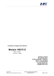
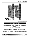
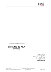
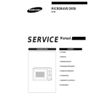
1
Operating instructions easyLINE Issue: June 2013 Article no.: 1040582 IEF Werner GmbH Wendelhofstraße 6 78120 Furtwangen - Germany Phone: +49 7723-925-0 Fax: +49 7723-925-100 www.IEF-Werner.de [email protected] June 2013 MAN_EN_1040582_easyLINE_R3a.doc Operating instructions easyLINE Page 1 of 34 Change History: Document Code Date Revision MAN_EN_1040582_easyLINE_R2b.doc 26.02.2007 Release of the english Document (“MAN_EN_ 1040582_easyLINE_R2b.doc”). Document updated regarding the new machinery directive (MRL 2006/42/EC). MAN_EN_1040582_easyLINE_R3a.doc 13.06.2013 Made from German document “MAN_DE_1040581_easyLINE_R3a.doc”. Trademarks and trade names are used without any warranty of their free usability. Texts and examples were created with great care. Nevertheless, errors cannot be excluded. IEF Werner GmbH does not assume legal responsibility nor any liability for missing or incorrect statements and their consequences. IEF Werner GmbH reserves the right to modify or improve the software or hardware or parts of it, as well as the supplied documentation or parts of it, without previous notice. IEF Werner GmbH expressly reserves all rights for replication and photomechanical reproduction, including in extracts. We are always grateful for suggestions for improvements and information about errors. © June 2013, IEF Werner GmbH Page 2 of 34 Operating instructions easyLINE June 2013 MAN_EN_1040582_easyLINE_R3a.doc Table of Contents 1 2 3 Safety 5 1.1 Definition or warning notes 5 1.2 General warning notes 5 1.3 Special hazard warnings 6 Intended use 7 2.1 Reasonably foreseeable misuse 7 Assembly instructions 8 3.1 Installation position 8 3.2 Overview of motor installation variants 8 3.2.1 Installation variant 1 9 3.2.2 Installation variant 5 9 3.3 Attachment 10 3.3.1 Mounting with clamping elements 10 3.3.2 Attachement at the carriage of the linear module 12 3.3.3 Installation of actuators 13 3.4 Wiring 14 3.4.1 Motors 14 3.4.2 Initiators 14 3.4.2.1 Plug end position switch 16 3.4.3 Cable routing 16 3.5 Technical data 17 3.5.1 Tightening torques for screw connections 17 3.5.2 Technical Data of easyLINE module 17 3.5.4 Technical data when using a planetary gear 18 3.5.5 Load cases 19 3.5.5.1 Torques and load carrying capacity 19 4 Maintenance 20 5 Trouble shooting 21 6 Repair instructions 23 6.1 Toothed belt tension 23 6.2 Belt tension gear toothed belt 23 Parts lists and drawings 24 7 June 2013 MAN_EN_1040582_easyLINE_R3a.doc Operating instructions easyLINE Page 3 of 34 8 7.1 easyLINE installation variant 1 24 7.2 Reversing unit easyLINE art.No. 526261 26 7.3 Carriage easyLINE completed (Article no. 526311) 27 7.4 Long carriage easyLINE complete (Article no. 526609) 28 7.5 Gearbox (Subassembly no. 1000002) 29 7.6 Flange i = 1:1 (subassamly no. 1000003) 30 7.7 easyLINE clamping block complete – exploded view (Article no. 526262) 31 7.8 easyLINE long carriage clamping block complete - exploded view (Article no. 526610) 32 7.9 easyLINE, parallel drive – exploded view 33 Declaration of incorporation 34 Page 4 of 34 Operating instructions easyLINE June 2013 MAN_EN_1040582_easyLINE_R3a.doc 1 Safety 1.1 Definition or warning notes WARNING Indicates potential danger. Non-observance of the safety provisions may cause death or severe injury. CAUTION Indicates potential danger. Non-observance of the safety provisions may cause property damage or injury. NOTE 1.2 Offers additional information. General warning notes The module must only be commissioned by specialists who received safety-technical instruction and are able to assess potential dangers. Furthermore, all chapters of these operating instructions must have been read and understood completely. WARNING The system must be powered down for all assembly, disassembly or repair work. There is a high danger of injury. WARNING OF HOT SURFACE During operation, heating of the motor, in particular of stepper motors, can cause burns of the skin when touching the motor. Install a protective device, if possible! Do not touch the marked areas or wait for an adequate cooling time. CAUTION Motor connectors must not be inserted or disconnected when live. Risk of burning of the contacts and risk of flying sparks. June 2013 MAN_EN_1040582_easyLINE_R3a.doc Operating instructions easyLINE Safety Page 5 of 34 CAUTION Linear modules always have to be operated in connection with suitable safety devices (e.g., safety cell, protective room, protective housing, light curtain). NOTE 1.3 Observe the Manufacturer's Declaration (see section Declaration of incorporation, page 34). Special hazard warnings In addition, this operating instructions also contains the following special hazard warning: DANGER FROM CRUSHING These places of the components pose the danger of crushing limbs in operation. Safety Page 6 of 34 Operating instructions easyLINE June 2013 MAN_EN_1040582_easyLINE_R3a.doc 2 Intended use The easyLINE module (see Figure 1) is a precise, linear adjustment unit with toothed belt drive that is used in the commercial area as an attachment part in connection with other components. In combination with many standardised installation elements and the other linear modules of IEF Werner GmbH (e.g. module 68 and 68D, module 105, module 105 S, module 142 and module 142 S), complex multi-axis handling systems can be developed as well. Figure 1: easyLINE module The areas of application of an easyLINE module are accordingly diverse. They encompass: 2.1 Stop adjustment in the wood industry Equipment systems for SMD components Joining and press-in processes in precision mechanics Loading and unloading station of tool machines up to Manipulators for the packaging industry Reasonably foreseeable misuse The easyLINE module is not to be used for certain applications, and in particular not for such as the transport of persons and animals or as a pressing/bending device for cold working of metal. Use of the linear module without additional measures is also not possible in special fields of application, such as the chemical or food industry or in explosive atmospheres. In case of doubt, consult the manufacturer. June 2013 MAN_EN_1040582_easyLINE_R3a.doc Operating instructions easyLINE Intended use Page 7 of 34 3 Assembly instructions 3.1 Installation position The installation position is optional, i.e. the easyLINE module can be used horizontally as well as vertically. 92 177,2 CAUTION In the vertical installation position, use only motors with spring-operated brake to prevent the lowering of the drive in de-energized condition! 65 A 89 (Befestigungsmaß) 112 3.2 Overview of motor installation variants The generally variants of installation are (see Figure 2): Km5(2x) n 65 Installation variant 1 89 (Befestigungsmaß) 4; Km5(4x) A; B: Hubbegrenzung Endschalter : Referenzpunkt 103,5 A Installation variant 5 A; B: Hubbegrenzung Endschalter Figure 2: Installation variants easyLINE module A Assembly instructions Page 8 of 34 : Referenzpunkt Operating instructions easyLINE June 2013 MAN_EN_1040582_easyLINE_R3a.doc 3.2.1 Installation variant 1 A 65 B 177,2 92 68 stroke-eff. + 105 89 (mounting proportion) 112 stroke-eff. + 285 105 89 92 M6; 12 deep (4x) DIN74; Km5 (2x) option: easyLINE long carriage 194 M6x12 (10x) 105 92 89 DIN 74; Km5 (4x) 8 52,5 82 97 112 A, B: stroke limited switch 141,5 186 A: standard reference point Figure 3: easyLINE installation variant 1 3.2.2 Installation variant 5 stroke-eff. + 285 112 A 65 B 89 (mounting proportion) stroke-eff. + 105 68 105 89 92 103,5 M6; 12 deep (4x) DIN74; Km5 (2x) option: easyLINE long carriage 194 105 DIN 74; Km5 (4x) 92 89 M6;12 deep (10x) 8 52,5 82 97 112 A, B: stroke limited switch A: 141,5 186 standard reference point Figure 4: easyLINE installation variant 5 June 2013 MAN_EN_1040582_easyLINE_R3a.doc Operating instructions easyLINE Assembly instructions Page 9 of 34 3.3 Attachment 3.3.1 Mounting with clamping elements The use of clamping elements (see Figure 6) allows the linear unit easyLINE to be easily secured to a level mounting surface. Standard length clamping elements are available for the cross-mounting of linear units. For safety reasons, continuous clamping sections are advised. This ensures hazardous shear points are avoided. Please avoid additional drilling holes in the basic body. This might damage the internal parts of the linear unit and could distort the guide base. CAUTION The clamping area should have a planeness of 0.1 mm/m² Clamping element Bore distance Clamping element 89 Figure 5: Attachment with clamping elements Figure 6: Dimensions clamping element Assembly instructions Page 10 of 34 Operating instructions easyLINE June 2013 MAN_EN_1040582_easyLINE_R3a.doc CAUTION Observe the hazard points shown in Figure 7 and Figure 8 ! crushing position shearing points Figure 7: Attachment with standard-clamping elements crushing position Figure 8: Attachment with continiously clamping elements (no shearing points) June 2013 MAN_EN_1040582_easyLINE_R3a.doc Operating instructions easyLINE Assembly instructions Page 11 of 34 3.3.2 Attachement at the carriage of the linear module As a second possibility the linear module can be attached at its carriage (use easyLINE with a long carriage and a stroke longer than 300 mm). The basic body moves free. However, in this case the motor, motor cable, limit switch cable and also encoder or resolver cable have to be moved as well. Figure 9: Mounting example Via two borings M5 (see in Figure 10) the linear unit can be tighten up on a mounting table. A further mounting possibility is using the 4 threaded borings M6 (see ) possibly through a distance plate. 105 89 2 2 1 1 =DIN74; Km5 (2x) 92 2 =M6x12 (4x) 2 1 2 Figure 10: Mounting detail standard slide Both attachment variants are possible.The respective application determines the needed variant (long side, see Figure 11, page 13). Assembly instructions Page 12 of 34 Operating instructions easyLINE June 2013 MAN_EN_1040582_easyLINE_R3a.doc 194 2 2 1 1 2 2 2 2 105 92 89 2 2 2 2 1 1 8 1 =DIN74; Km5 (4x) 2 =M6x12 (10x) 52,5 82 97 112 141,5 186 Figure 11: Mounting detail long slide 3.3.3 Installation of actuators Actuators (pick-up modules, cylinders etc.) to be installed on the module easyLINE are usally attached to the linear unit using the drill template of the end plates, see Figure 10 , page 12 or Figure 11, above. If you assemble according to Figure 9, page 12, you can mount the actuators according to the mounting example of Figure 12, below. Only very light elements (less than 1 kg) can be attached directly on the end plate. In this case, you should equip the end plate with a suitable mounting plate. mounting plates end plate clamping element Typ 105 Figure 12: Mounting example June 2013 MAN_EN_1040582_easyLINE_R3a.doc Operating instructions easyLINE Assembly instructions Page 13 of 34 3.4 Wiring 3.4.1 Motors CAUTION The electrical connection of the motors is performed according to the motor data sheet. For customer-specific motors, the data sheet must be requested from the respective manufacturer and the motor connected accordingly. 3.4.2 Initiators Inductive proximity switches (PNP normally closed contacts, article no.: 025165 see Figure 14) are used as standard limit switches for the running path. These switches are no safety limit switches pursuant to EN60204-1. Optionally, (also subsequently) an additional reference point switch (PNP normally open contact article no.: 726744, see Figure 13), can be installed in the easyLINE module. The active button is marked with a coloured circle. Normally closed contacts are marked with a green, normally open contacts with a red dot. The initiators and their supply lines are protected in a cable channel integrated in the basic body and are wired to a joint plug. A plastic strip serves to cover the cable channel. An initiator can be replaced or relocated easily after removal of this plastic strip from the cable channel. brown + 24VDC black signal blue 0V Figure 13: Connection allocation PNP normally open contact brown + 24VDC black signal blue 0V Figure 14: Connection allocation PNP normally closed contact Assembly instructions Page 14 of 34 Operating instructions easyLINE June 2013 MAN_EN_1040582_easyLINE_R3a.doc 4 9,9 1 M4 40 20 5 active area Figure 15: Dimensions initiator Technical data of initiators Parameter Value Operating voltage, incl. residual ripple 10...30 VDC 15 % Current load capacitiy Ia 200 mA Switching frequency 1000 Hz Consume current 15 mA Nominal switch distance at steel 1.5 mm 10 % Switching hysteresis (3...20) % Reproducibility (U = konst.) 0.1 mm Operating temperature - 25 ... + 70 C Protection class IP 65 Short-circuit proof yes Reverse battery protection yes Figure 16: Technical data of initiators June 2013 MAN_EN_1040582_easyLINE_R3a.doc Operating instructions easyLINE Assembly instructions Page 15 of 34 3.4.2.1 Plug end position switch The end position switch is assigned as follows (see Figure 17) Pin-No. Assignment IEF Werner cables 1 + 24 V brown 2 Limit switch negative direction green 3 0V white 4 Limit switch positive direction yellow 5 Reference switch grey Figure 17: Connection assignment plug end position switch 3.4.3 Cable routing For all moving cables, suitable cable routing has to be used to effectively prevent cable breaks. The minimum radius rmin for cable carriers results from the following formula: rmin 10 x cable diameter When different cables are used, EN 60204 must be observed. In addition, it must be ensured that a space reserve of 30% is kept free within the routing chains. A strain relief for the cables has to be attached at the outlet of the cable routing chain. We recommend to procure original cables and cable routing chains from IEF Werner. Please contact us, we will be pleased to provide advice. Assembly instructions Page 16 of 34 Operating instructions easyLINE June 2013 MAN_EN_1040582_easyLINE_R3a.doc 3.5 Technical data 3.5.1 Tightening torques for screw connections Screw 8.8 M3 1.1 M4 2.5 M5 5.0 M6 8.5 M8 21.0 M10 41.0 M12 71.0 Screw 12.9 M4 (fixation of guiding rail) 3.5.2 Tightening torque [Nm] Tightening torque [Nm] 4.9 Technical Data of easyLINE module Parameter Value Repeating accuracy +/- 0.04 mm Weight (without motor, without planetary gearbox) at stroke 0 mm 4.4 kg Weight increase per 100 mm stroke 0.7 kg Maximum speed 2.5 m/s Torque Mx 35 Nm Torque My 50 Nm Torque Mz 20 Nm Static load carrying capacity C1 1000 N Static load carrying capacity C2 550 N June 2013 MAN_EN_1040582_easyLINE_R3a.doc Operating instructions easyLINE Assembly instructions Page 17 of 34 3.5.3 Type label easyLINE Figure 18: Type lable (example) 3.5.4 Technical data when using a planetary gear Before commissioning, observe the possible input speeds of the gear manufacturers. Too-high input speeds can lead to increased wear at the gear and/or thermal problems. The accuracy of the linear unit is influenced by the reverse play of the gears. Example: The gear reverse play (S) is 9 angle minutes. How high is the reverse play at the carriage of the linear unit? Infeed constant of the linear unit (Vk): 140 mm Reverse play at the carriage = (Vk • S) / (360 x 60) = (140 mm • 9) / (360 x 60) = 0.058 mm Consider the information of the respective gear manufacturer in any case. e.g. http://www.neugart.de/index.php/gb/Produkte/Standardgetriebe http://www.wittenstein-alpha.de/en/drive-systems.html Assembly instructions Page 18 of 34 Operating instructions easyLINE June 2013 MAN_EN_1040582_easyLINE_R3a.doc 3.5.5 Load cases 3.5.5.1 Torques and load carrying capacity Figure 19: easyLINE load capacitiy Extract of technical data (see chapter of Technical Data of easyLINE, page 17) Parameter Value Maximum torque Mx 35 Nm Maximum torque My 50 Nm Maximum torque Mz 20 Nm Static load carrying capacity C1 1000 N Static load carrying capacity C2 550 N June 2013 MAN_EN_1040582_easyLINE_R3a.doc Operating instructions easyLINE Assembly instructions Page 19 of 34 4 Maintenance During the design of the linear unit easyLINE, great importance was placed on the use of lowmaintenance components. All roller elements were provided with lifetime lubrication in the factory. To avoid danger of over-lubrication of the linear bearings, no external lubrication nipples were attached to the carriage part. However, to achieve a high service life of the wipers, we recommend moistening the guide shafts with special grease at regular intervals. The lubricant may be procured from IEF in tubes of 50 gr (Art. no.732934) each: The recommended maintenance intervals add up to approx. 200 operating hours under regular ambience conditions. The maintenance intervals should be reduced for unfavourable ambient conditions. Maintenance Page 20 of 34 Operating instructions easyLINE June 2013 MAN_EN_1040582_easyLINE_R3a.doc 5 Trouble shooting Interference Increased running noise Reason Correction Nominal service life of linear bearings is exceeded Replace all linear bearings Linear bearings worn from overload (too-high torque, etc.) Replace all linear bearings, reduce load Linear bearings worn of strong contamination Replace all linear bearings, clean guide elements more often if required Guide shafts worn Replace guide shafts, replace linear bearings if required, check load, protect linear module from strong contamination Guide shafts corroded Replace guide shafts, replace linear bearings if required, lubricate guide shafts more often Reversing unit worn Replace reversing unit Drive unit worn Replace drive unit Toothed belt runs dry Slightly lubricate toothed belt on the toothed side Toothed belt tension too high Install reconciled spacer sleeves Toothed belt doesn`t move straight Align toothed belt with belt fastener (carriage plate and tappet), install reconciled spacer sleeves Toothed belt strongly Replace toothed belt, protect linear module from contaminated on thoothed inner strong contamination side Toothed belt defective Replace toothed belt Motor (motor bearing) defective Replace motor The linear module doesn't move Motor with brake, brake does not open Apply current to the brake, if the brake still does not open, replace motor Limit switch cable not connected Connect the cable Limit switch defective Change initiator Limit switch cable defective Check limit switch cable, replace cable, if required Solder connection on socket has come lose Solder on wires Motor connection incorrectly Check and change connector assignment, if required Motor defective Replace motor Error in power electronics or control unit Check power electronics or control unit motor cable defective Check motor cable, replace cable, if required June 2013 MAN_EN_1040582_easyLINE_R3a.doc Operating instructions easyLINE Trouble shooting Page 21 of 34 Interference Reason Correction Toothed gear belt not tensioned Tension toothed gear belt Toothed motor pulley wheel has Replace the toothed motorwasher, replace the clearance (keyway) motor if the keyway of the motor shaft is Play on reversal damaged Toothed drive belt not tensioned Linear drive unit Incorrect direction of rotation moves Broken motor cable mechanically against the stop during the reference run Trouble shooting Page 22 of 34 Pull the reversing unit back towards it's limit stop (spacer bushing) Change motor direction of ratiotion Replace cable Operating instructions easyLINE June 2013 MAN_EN_1040582_easyLINE_R3a.doc 6 Repair instructions WARNING Always power down the system before starting repairs. WARNING Any repairs must only be performed by specialist personnel who have read and understood the operating instructions. CAUTION Only use original replacement parts, otherwise IEF Werner GmbH will not accept any warranty. 6.1 Toothed belt tension The toothed belt tension for easyLINE is set with spacer sleeves. (see drawing item 40 in Figure 21, page 26) 6.2 Belt tension gear toothed belt The belt tension of the gear toothed belt should be 150 N. (see drawing item 10 in Figure 24 page 29) June 2013 MAN_EN_1040582_easyLINE_R3a.doc Operating instructions easyLINE Repair instructions Page 23 of 34 7 Parts lists and drawings 7.1 easyLINE installation variant 1 Drawing item Articleno. Part (1) / subassembly (0) + Designation 1000003 0 + Flange 525929 1 + Coupling (only for parallel drive, see chap. 7.9) 730889 1 + Aluminium tube (only for parallel drive, see chap. 7.9, page 33) 10 1000002 0 + Gearbox 20 1000041 0 + Motor 30 526637 1 + Drive unit easyLINE two shafts (only for parallel drive see chap 7.9, page 33) 30 526260 1 + Drive unit easyLINE parallel drive (only for parallel drive see chap 7.9, page 33) 30 526259 1 + Drive unit easyLINE 40 030312 1 Cover plate easyLINE 50 030342 1 Housing easyLINE 60 028689 1 + Cover plate easyLINE 60 030431 1 + Plastic cover easyLINE (chap 7.9, page 33) 70 732284 1 Plastic cover D=25/20.5 black 80 725164 1 Plug WKV 50/6 100 725163 1 Socket plug SFV 50/6 110 025626 1 Holding plate 120 1000009 0 Basic unit easyLINE 130 025165 1 Limit switch PNP-NC 130 726744 1 130 627085 1 Headless screw 130 028585 1 Limited switch holder 140 028668 1 Plastic clip 150 028688 1 Cover strip 160 526261 1 Reversing unit easyLINE 170 732766 1 Toothed belt 25AT5 180 526311 1 + Carriage easyLINE complete 180 526609 1 + Long carriage easyLINE complete 190 526289 1 + Limit switch PNP-NO Stopper easyLINE complete + depending on design June 2013 MAN_EN_1040582_easyLINE_R3a.doc Operating instructions easyLINE Parts lists and drawings Page 24 of 34 10 20 30 190 40 180 50 60 70 170 80 160 140 100 110 120 130 140 150 Figure 20: easyLINE exploded view June 2013 MAN_EN_1040582_easyLINE_R3a.doc Operating instructions easyLINE Parts lists and drawings Page 25 of 34 7.2 Reversing unit easyLINE (Article.No. 526261) Drawing item Article Part (1) / no. subassembly (0) + Designation 10 030313 1 Cover plate easyLINE 20 028580 1 Housing reversing unit easyLINE 30 527282 1 Pulley easyLINE 40 027736 1 Spacer sleeves (for limitation and controling the tension of the toothed belt) 50 028576 1 Endplate easyLINE 50 40 30 20 10 Figure 21: easyLINE, reversing unit exploded view Parts lists and drawings Page 26 of 34 Operating instructions easyLINE June 2013 MAN_EN_1040582_easyLINE_R3a.doc 7.3 Carriage easyLINE completed (Article no. 526311) Drawing item Article no. Part (1) / subassembly (0) 10 028581 1 Belt receptacle easyLINE 20 028577 1 Carriage plate easyLINE 30 526262 1 Clamping block easyLINE complete 10 026481 1 Bumper green 20 028584 1 Clamping block easyLINE See clamping block complete exploded view 30 626046 1 Linear bearing Chapter 7.7, page 31 40 1000492 1 Fixing screw 40 626059 1 Cylinder head screw DIN 912-M5x16-8.8 50 626488 1 Cylinder head screw DIN 912-M5x12-8.8 + Designation 50 40 20 10 30 Figure 22: easyLINE, carriage complete June 2013 MAN_EN_1040582_easyLINE_R3a.doc Operating instructions easyLINE Parts lists and drawings Page 27 of 34 7.4 Long carriage easyLINE complete (Article no. 526609) Drawing item Article no. Part (1) / + subassembly (0) 10 028581 1 Belt receptacle easyLINE 20 028919 1 Long slide plate easyLINE 30 526610 1 Long slide clamping block easyLINE cpl. (see chapter 7.8, page 32) 10 026481 1 Bumper green 20 028918 1 Double clamping block easyLINE Designation See clamping block complete exploded view Chapter 7.8, page 32 30 626046 1 Linear bearing 40 1000492 1 Fixing screw 40 626059 1 Cylinder head srew DIN 912-M5x16-8.8 50 626488 1 Cylinder head srew DIN 912-M5x12-8.8 50 40 20 50 30 10 Figure 23: easyLINE, long carriage complete Parts lists and drawings Page 28 of 34 Operating instructions easyLINE June 2013 MAN_EN_1040582_easyLINE_R3a.doc 7.5 Gearbox (Subassembly no. 1000002) Drawing Article. item no. Part (1) / subassembly (0) + Designation 1 + Toothed belt 10 20 526628 30 40 1 Housing of the gearbox 1 527263 50 + 1 Driven washer Clamping set 15/28 1 + Washer for motor +use depending on design 10 20 50 Motor toothed disc Typ 3 40 30 Typ 1 Typ 2 Figure 24: easyLINE, gearbox exploded view June 2013 MAN_EN_1040582_easyLINE_R3a.doc Operating instructions easyLINE Parts lists and drawings Page 29 of 34 7.6 Flange i = 1:1 (Subassamly no. 1000003) Partsgroup no. 1000003 Drawing item Article no. Part (1)/ subassembly (0) 10 028680 1 Motor flange i=1:1 20 1064076 1 Coupling d=15mm 30 1064079 1 Elastomere rim 98sh red 40 1 + + Designation Coupling (motorside) +use depending on design 10 20 30 40 Figure 25:easyLINE Flange i=1:1 CAUTION Please additionally observe the wear parts lists included with the delivery according to the order Parts lists and drawings Page 30 of 34 Operating instructions easyLINE June 2013 MAN_EN_1040582_easyLINE_R3a.doc 7.7 easyLINE clamping block complete – exploded view (Article no. 526262) 30 20 10 40 small distance Please pay attention ! Figure 26: easyLINE clamping block complete June 2013 MAN_EN_1040582_easyLINE_R3a.doc Operating instructions easyLINE Parts lists and drawings Page 31 of 34 7.8 easyLINE long carriage clamping block complete - exploded view (Article no. 526610) 30 20 10 40 Please pay attention ! Figure 27:easyLINE clamping block complete Parts lists and drawings Page 32 of 34 Operating instructions easyLINE June 2013 MAN_EN_1040582_easyLINE_R3a.doc 7.9 easyLINE, parallel drive – exploded view Sectional view coupling (M1:2) Article.-No.: 1063253 Tightening torque: 8,5 Nm Master axis Clamping screw Tightening torque: 12 Nm Slave axis Figure 28: easyLINE parallel drive June 2013 MAN_EN_1040582_easyLINE_R3a.doc Operating instructions easyLINE Parts lists and drawings Page 33 of 34 8 Declaration of incorporation EC declaration of incorporation in the sense of the EC directive 2006/42/EC (machinery), Annex II B The manufacturer: IEF Werner GmbH Wendelhofstraße 6 78120 Furtwangen - Germany hereby declares that the following products (the incomplete machine/partial machine): Designation IEF Werner subassambly number easyLINE TG1000010 where possible based on the scope of delivery, correspond to the following basic requirements of the directive on Machinery (2006/42/EC): Annex I, item: 1.1.2; 1.1.3; 1.1.5; 1.3.2; 1.3.4; 1.5.1; 1.7.3. The incomplete machine also corresponds to the following further directives: Directive 2004/108/EC of the council, dated 15 December 2004, for harmonisation of the legal provisions of the member states on electromagnetic compatibility. Directive 2006/95/EC of the council, dated 12 December 2006, for harmonisation of the legislation of the member states regarding electrical equipment for use within specified voltage thresholds. The technical documents were generated according to Annex VII part B and may be electronically submitted to the national authorities upon justified request. List of some applied harmonised standards: EN ISO 12100-1,-2 / EN ISO 13857 / EN ISO 13850 / EN 60201-1 Commissioning of the incomplete machine delivered by us is not permitted until it has been determined that the overall system into which the incomplete machine is installed meets the basic safety and health protection requirements according to Annex I of the above EC directive 2006/42/EC. Name of the documentation officer: Frank Reichelt, technical editor Address of the documentation officer: see manufacturer's address Furtwangen, 06 February 2010 Declaration of incorporation Page 34 of 34 Operating instructions easyLINE Manfred Bär (manager) June 2013 MAN_EN_1040582_easyLINE_R3a.doc