1
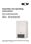
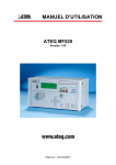
DWT
Installation
and
Operating instructions
Digital weather-compensated
controller DWT
for gas fired boilers
Wolf GmbH · Postfach 1380 · 84048 Mainburg · Tel. +49-8751/74-0, Fax +49-8751/741600, Internet: www.wolf-heiztechnik.de
Part no. 30 61 347
Subject to technical modifications
6.6701.605
05/05
GB1
Index
Index
DWT
Page
Summary of functions .............................................................................................................................. 3
Terminology ............................................................................................................................................. 4
Standards and regulations ....................................................................................................................... 4
Assembly .................................................................................................................................................. 5
BUS interface setting ............................................................................................................................... 6
Electrical connection ................................................................................................................................ 7
Control level ....................................................................................................................................... 8-9
Program selection ........................................................................................................................ 8
Function display ........................................................................................................................... 8
Temperature selection – heating mode ....................................................................................... 9
Economy key ............................................................................................................................... 9
Party key ...................................................................................................................................... 9
Programming level ....................................................................................................................... 10-24
DWT controls ............................................................................................................................. 10
Summary of functions ............................................................................................................... 11
Standard settings ...................................................................................................................... 12
Time ................................................................................................................................... 12
Day .................................................................................................................................... 12
Time program ..................................................................................................................... 13
Economy temperature ....................................................................................................... 14
Heating curve .................................................................................................................... 14
Room influence .................................................................................................................. 15
Language selection ........................................................................................................... 15
Heating DHW once ............................................................................................................ 15
Summer/winter .................................................................................................................. 15
Heating program ................................................................................................................... 16-17
Domestic hot water program ............................................................................................... 18-19
Displays ..................................................................................................................................... 20
Heating contractor ................................................................................................................ 21-25
Auxiliary functions ........................................................................................................................ 25-26
Automatic summer/winter changeover ............................................................................ 25
Room temperature dependent frost protection ................................................................ 26
Partial RESET ..................................................................................................................... 26
Complete RESET ................................................................................................................ 26
Processor RESET .............................................................................................................. 26
Emissions test mode ......................................................................................................... 26
Fault display ...................................................................................................................... 26
Fault codes ........................................................................................................................................... 27
Sensor resistances ........................................................................................................................... 28
Specification ........................................................................................................................................ 29
Parameter setup report ................................................................................................................... 29
Setup report - switching times ...................................................................................................... 30
Notes ................................................................................................................................................... 31
Safety instructions
2
The following symbols are used in conjunction with these
important instructions concerning personal safety as well as
operational reliability.
"Safety instructions" are instructions with which you
must comply exactly, to prevent injury and material
losses.
This indicates technical instructions which you must
NB
observe to prevent material losses and boiler
malfunctions.
Summary of functions
1
2
0
6
3
4
12
5
6
DWT
7
18
24
1
P
Front flap
Program selector key
Party key
Economy key
Heating program: shows the set times for heating
and economy mode
Temperature selection –
heating mode
Day (1 = Mo,..., 7 = Su)
Room temperature
Time
Function display
Heating mode /
economy mode
display
Program selection display
3
Terminology / Standards and regulations
Terminology
DWT
Heating water temperature
The heating water temperature is the radiator flow temperature. The
higher the heating water temperature, the higher the heat transfer to
radiators.
Boiler
Gas fired boiler, which can be combined with a DHW cylinder.
Combi boiler
Gas fired boiler with an instantaneous water heater and DHW QuickStart.
Cylinder heating
Heating up the DHW cylinder.
DHW QuickStart
The heating water in the boiler will be held at a certain temperature during
summer mode, to be able to supply hot water as rapidly as possible from
the instantaneous water heater of the combi boiler. The DHW time program
switches this function ON and OFF during summer mode.
Heating program
Subject to program selection, the heating time program switches the gas
fired boiler from heating to economy mode or from heating mode to heating
OFF and vice versa.
Domestic hot water program
In a combi boiler, the DHW time program controls the DHW QuickStart, and
for a boiler with a DHW cylinder, the cylinder heating ON and OFF.
Winter mode
Central heating and DHW according to the heating and DHW time program.
Summer mode
Central heating OFF, DHW according to the DHW time program.
Heating mode/economy mode
In winter mode, two room temperatures can be selected. One for central
heating and one for economy mode, when the room temperature will be
setback to the economy temperature.
The heating program changes over between heating and economy mode.
Standards and regulations In gas fired combi boilers, the DWT digital weather-compensated thermostat
complies with the following Directives:
- Gas Equipment Directive
- Low Voltage Directive
- EMC Directive
4
Assembly
Assembly
DWT
- Install the DWT on an internal wall at a height of approx. 1.5 m.
- Install the DWT in a living room, which is representative of the entire living
space.
- The DWT must not be subject to draughts or radiated heat.
- The DWT must not be obstructed by furniture or curtains.
- In this room, all radiator valves must be fully opened.
- Remove the base from the DWT.
Fixing holes
Connection
eBUS or
SCOM interface
Plug to the top
part
- Secure the thermostat base on the flush-mounting box (Ø55 mm) or with
the rawl plugs supplied directly to the wall.
5
BUS interface setting
DWT
BUS interface setting
(eBUS or SCOM)
Wolf boilers are equipped either with an eBUS or a
SCOM interface for control accessories. The interface
can be selected with DIP switch 4 at the back of the
DWT.
Connection to Wolf boilers
with eBUS interface
(CGB, CGS, TGC)
DWT
For boilers with eBUS interface, the BUS terminals
"+" and "-" are marked together with "eBUS".
Push the DIP switch 4 into the ON position. Switches
1 to 3 remain OFF, if only one DWT is connected.
a b +
A F
E1 eBUS AF
ON
24 V
DIP
1 2 3 4
ON “eBUS”
OFF “SCOM”
Dip 1-4
Setting the eBUS address
Using DIP switches 1-3, set one address for every
DWT in systems with several DWT controllers
(multi-boiler system with DWTM).
eBUS
settings
Einstellung
eBUS
Adresse 0 (Werkseinstellung)
Address
(factory setting)
Adresse 11
Address
Address
Adresse 22
Address
Adresse 33
Address
Adresse 44
Address
Adresse 5
Adresse 6
Address
Address
Adresse 77
Address list at the back of the controller PCB
Connection to Wolf boilers with SCOM
interface
(TGU, TGG, GU-2, GG-2,
TGB-11/20/40/60, GB-20-S)
a
AF
Zubehör
24VAC
24VDC
-
+
b
ON
AF
Zubehör
24VDC
b
-
+
24V
!
a
DRT
0V
24VDC
DIP
1 2 3 4
For boilers with SCOM interface, the BUS terminals
"+" and "-" are marked in accordance with connection
diagrams with "(Wolf) accessories". Push switches
1 to 4 into the OFF position.
See DWTM installation and operating instructions if
the DWT is set up as remote control for DWTM.
ON “eBUS”
OFF “SCOM”
Dip 1-4
Note: In case of replacement for systems with DWT (part no. 27 33 002) and DWTM (part no. 27 33 007):
Remove any jumper which may be inserted in the DWT base between terminal 3 and 4. DIP switch settings
at the back of the DWT subject to parameter 19 in the DWTM:
a) Parameter 19 = 0 (DWTM) ON DIP
a) Parameter 19 = 1 (DWTM) ON DIP
1 2 3 4
NB
1 2 3 4
All accessory controllers (BUS users) must be set to the same boiler interface (eBUS or SCOM).
A correctly adjusted BUS address, and with that the communication between all users, is
indicated at every controller approx. 1 minute later.
1
2
0
BUS connection active
6
6
1
3
4
12
5
6
18
7
24
Electrical connection
NB
The electrical connection must only be
carried out by a qualified electrician.
NB
Do not route these cables
alongside mains power cables.
DWT
Connection version a)
+
1
2
5
6
DWT terminal
strip
ϑ
Wire the DWT with a 2-core cable (minimum
cross-section 0.5 mm²) to the gas fired boiler.
Subject to boiler terminal strip, select one of the
adjacent wiring diagrams.
A
ϑ
E1
Telecontrol contact
for eBUS
and SCOM
Connection
eBUS or
SCOM interface
a b +
24 V
eBUS
F
AF
DWT base:
Connection
of outside
temperature
sensor
3 4
+ 1 2
5 6
Outside
temp. sensor
(alternative)
Outside
temp.
sensor
Boiler
terminal strip
Connection version b)
+
1
2
5
6
DWT terminal strip
ϑ
Outside temp.
sensor
(alternative)
b
Connection version c)
2
5
6
DWT terminal strip
AF
Zubehör
0V
24VDC
Outside temp.
sensor (alternative)
+
!
24V
ϑ
ϑ
Boiler
terminal strip
b
Outside temp.
sensor
a
+
1
24VDC
- The outside temperature sensor may be
connected either to the boiler or to the DWT.
- Install the outside temperature sensor at a
north or north-eastern wall at a height of
2-2.5 m above the ground (cable grommet
pointing downwards).
Boiler
terminal strip
a
24VAC
+
-
Zubehör
AF
ϑ
Reposition the DWT onto its base and click into
place. When refitting the housing ensure, that
the contact pins on the thermostat are not bent.
24VDC
Outside temp.
sensor
7
Control level
DWT
Program selection
1
2
0
6
3
4
5
12
6
18
7
24
1
P
Program selector key
Important: This must be set to
Economy key
Party key
Temperature selection –
heating mode
for gas fired boilers with program selector.
Operating Display mode
prog. select.
Central
heating
DHW
boiler
DHW
combi boiler
Standby
Central heating OFF /
Frost protection
Cylinder heating OFF
DHW QuickStart OFF
Summer
mode
Central heating OFF /
Frost protection
Cylinder heating according to
DHW program
DHW QuickStart acc.
to DHW program 1)
Winter
mode
Economy mode
Cylinder heating according to
DHW program
Heating mode
Cylinder heating according to
DHW program
Heating or economy mode
Cylinder heating according to
according to heating program DHW program
Heating mode or central
heating OFF according to
heating program
Cylinder heating according to
DHW program
1) Only for equipment with DHW QuickStart
Function display
8
Connection to the gas fired boiler OK
Heating circuit pump ON
Heating mode
Cylinder heating or DHW draw-off ON
Burner ON
Control level
Temperature selection –
heating mode
DWT
Setting the required room temperature for heating mode. This setting only
applies to heating mode, not to economy mode.
Turning the selector changes the display from current room temperature
to set room temperature.
Then you can change the desired room temperature for heating mode. If
no change is made within 2 s, the display will again show the current
room temperature.
Note: The set value only applies to the room temperature of the room in
which DWT is installed in case of room temperature dependent heating
mode (heating curve = 0) or for weather-compensated heating mode
with room influence (see room influence). The set temperature is only an
approximate value for purely weather-compensated control (heating
curve 0.2 – 3.0 and room influence = 0).
Economy key
If you press
, four zeros will appear in the display; further pressing
will set the control unit for one hour to economy mode, irrespective of
the heating program selected. If the boiler is already operating in
economy mode, this mode will be extended by a further hour. Pressing
again will extend the economy mode by a further hour, pressing
will reduce the current operation by one hour. The indicator will
return to 0 if more than 24 hours are entered. The room temperature will
again be displayed 5 s after the last input. The previously selected
economy mode can be cancelled again by pressing
.
Party key
The display will show four zeros after pressing . The control unit will
select one hour heating mode, if this key is pressed again, independent
of the heating program selection. If the boiler is already operating in
heating mode, this mode will be extended by a further hour. Pressing
again will extend the heating mode by a further hour, pressing
will
reduce the current operation by an hour. The indicator will return to 0
if more than 24 hours are entered. The room temperature will again be
displayed 5 s after the last input. The previously selected heating mode
can be cancelled again by pressing
.
Note:
The economy and party keys have no effect on DHW heating.
9
Programming level
DWT controls
DWT
After opening the front flap, the control unit changes to programming
mode and the display shows STANDARD SETTINGS. With the open flap,
the following settings can be displayed or modified:
Reset button
Red indicator
illuminates,
if the parameter can
be modified
-1x
Front flap
-
Programming keys
Legend for the adjacent table:
1)
Only with eBUS interface
2)
An additional time program will be displayed for the mixer circuit
only, if the DWT is used as remote control unit for the DWTM.
Mixer circuit symbol
Symbol for direct heating circuit
10
Programming level (summary of functions) DWT
Open front
flap
Standard settings
Time
Day
Heating program
2)
Changing the
heating switching
times of the set
time program
DHW program
Changing the DHW
switching times of the
set time program
Displays
Actual DHW
temperature
Outside temp.
Actual heating
water temp.
Time program
select (1 - 4)
Contractor
level
Heat-up optim.
or
Max. heat-up time
or
Req. heat-up time
or
Outside temp.
delay
Flow temp.
2)
Economy mode
Heating curve slope
Fan speed
or modulation
Heating curve slope
2)
Burner op. time
Matching room
temp. sensor
18 Max. limit for
parameter 28 1)
23 Ext. sensors
25 Pasteurisation
function 1)
Room influence
or
Burner starts
26 Maintenance
message
Set DHW
temperature 1)
27 Interval
maint. message
Language selection
D, F, GB, I, NL, ES,
CZ, SK, PL, HU
28
Screed drying 1)
29 Rem. cont.
1 or 2 circuits 1)2)
30
Frost limit 1)2)
40 GB param.1)
Back
Back
Back
Back
Back
Standard settings
Heating program
DHW program
Displays
Contractor
level
Close front
flap
Operating level
11
Programming level (standard settings)
DWT
All adjustable parameters as well as four time switch programs are set
at the factory and saved to non-volatile memory. After commissioning, only
the time and day of the week must be adjusted on-site.
Standard settings
Access to standard settings only requires opening the front flap. For
access to this level press
. Select individual parameters with
and
.
Parameter
Display
Time
TIME
Day
MONDAY
Time program
TIME PROG
Economy temp.
ECONOMY
TEMP
Heating curve
direct heating circuit
Heating curve
mixer circuit 2)
Room influence
10:00
Language
selection
Settings
range
Change
10:00
00:00-24:00
or
Monday
01
Monday – Sunday
1-4
or
12.0°C
12 °C
5 - 30 °C
or
HEATING CURVE
1.2
1.2
0-3
or
HEATING CURVE
0,8
0.8
0-3
or
0
0 - 20
or
60
15 - 65 °C or
40 - 63 °C
or
D
D, F, GB, I, NL, ES,
CZ, SK, PL, HU
or
00
ROOM INFL
DHW temp.
)
6 0 °C
D F GB I
1)
Only with eBUS interface;
this leaves the DHW thermostat at the boiler disabled.
2)
Will only be displayed, if the DWT is used as remote control unit for the DWTM.
12
or
1
(
Set DHW
temperature 1)
Factory
setting
Programming level (standard settings)
The digital weather-compensated control thermostat has four time programs
for heating and DHW mode, which are preset at the factory. For switching
times, see the following table.
All time programs can be modified and saved.
Time program
Time program 1
DWT
Heating
and
DHW
Mo-Su
6:00 - 22:00
Mo-Su
5:00 - 22:00
6:00
7:00
5:00
6:00
-
Day program
Mo-Su
Time program 2
Heating
and
DHW
Mo-Fr
Sa-Su
Mo-Fr
Sa-Su
8:00 and 16:00 - 22:00 Simple day program
23:00
Mo-Fr and Sa-Su
8:00 and 15:00 - 22:00
23:00
Time program 3
Heating
and
DHW
Mo, Tu, We, Th, Fr, Sa, Su 8:00 - 23:00 Individual times can be set
for every day
Mo, Tu, We, Th, Fr, Sa, Su 7:00 - 23:00
Time program 4
Heating
and
DHW
Mo, Tu, We, Th, Fr
Sa, Su
Mo, Tu, We, Th, Fr
Sa, Su
7:00 - 16:00 Individual times can be set
—
— for every day
6:00 - 16:00
—
—
13
Programming level (standard settings)
DWT
Economy temperature
During economy mode the temperature selected in the standard setting
ECON TEMP applies, not the temperature selected at the rotary selector.
The set economy temperature is only an approximate value when the room
influence = 0.
Heating curve
This selection will be made by the heating contractor separately for each
heating circuit, subject to the heating system, the thermal insulation of
the building and the relevant climatic zone.
Setting the gradient of the heating curve will match the heating water
temperature to these conditions.
Diagram 1 indicates an example applicable to the following heating
system:
- climate zone with average minimum outside temperature of -14 °C
- radiators for flow/return temperatures 60/50 °C
For all other conditions, match the gradient to the prevailing circumstances.
The slope must always be set so that, at the min. outside temperature,
the max. radiator flow temperature or that of the underfloor heating
system will be achieved.
As rule of thumb, a slope of 1.0 to 1.4 can be used for a radiator heating
system, and a slope of 0.4 to 0.8 for underfloor heating systems.
2,5
.
3
100
2
80
1,6
.
1,4
.
70
1,2
.
60
1
50
.
0,8
40
0,6
.
30
30
Gradient
Steilheit
Vorlaufsolltemperatur
[ °C
]
Set flow temperature
[°C]
90
.
0,4
25
30
0,2
.
25
Raumsollwert
Set
room temp.[°C]
°C
((Parallelverschiebung)
parallel offset ]
20
10
15
10
5
10
5
0
20
18
16
14
12
10
8
6
4
2
0
-2
-4
-6
-8
-10
-12
-14
-16
Außentemperatur [ °C ]
Outside temperature [ °C ]
From heating curve gradient 1.0 upwards, low end raising provides
sufficient comfort for higher outside temperatures in rooms equipped
with radiators.
Please note: A purely room temperature dependent heating water
temperature control results automatically, if the heating
curve is set to 0.
14
Programming level (standard settings)
Room influence
DWT
The room temperature sensor integrated into the weather-compensated
DWT controller can be included in the calculation of the heating water
temperature. You can adjust the extent to which the room temperature
sensor influences the calculation by various room temperature influencing
factors (K = 0 - 20). The higher the selected factor, the greater the effect
of the room temperature sensor. If no outside temperature sensor is
installed or an outside temperature sensor lead break is recognised
(resistance = infinite), the system will automatically operate purely as a
room thermostat.
Room influence K = 0 ! purely a weather-compensated heating
water temperature
Room influence K = 20 ! purely room temperature dependent heating
water temperature
Please note:
When using the DWT as remote control unit for the DWTM:
The room influence will only apply for the addresses selected with the DIP
switches, if both heating circuits are remote controlled by the DWT
(par. 29 at the DWT set to 1).
Address 0 = room influence applies to the direct heating circuit
Address 1 = room influence applies to the mixer circuit
Language selection
The following languages may be selected:
D
F
GB
I
NL
ES
CZ
SK
PL
HU
Heating DHW once
-1x
-
Summer/winter
German
French
English
Italian
Dutch
Spanish
Czech
Slovakian
Polish
Hungarian
If DHW is required outside the period where DHW heating is enabled, the
DHW cylinder can be heated to the set temperature by means of function
"1 x DHW".
Pressing keys
and
simultaneously with the front flap open either
activates or deactivates this function.
Function "1 x DHW" will be deactivated automatically after one hour.
To select the current summer/winter time, adjust the relevant time, as
described on page 12 (not required when connecting a radio clock
module).
15
Programming level (heating program)
DWT
Modifying switching times You can individually modify the switching times of the time programs
(Heating program)
(1 - 4) selected under the standard setting TIME PROG in the heating
program. Three ON and OFF times are available for the individual days
displayed. Always enter ON and OFF times as pairs.
Setting example
Access to standard settings only requires opening the front flap. Select
HEAT PROG with or . For access to this level press
.
Display acc. to time program
(here for example time program 3)
MONDAY
1
2
3
4
5
6
7
1st heating mode start-up time (call-up)
8:00
01
I
1
2
3
4
5
6
7
8:00
01
1st heating mode start-up time
red indicator illuminates
I
1
2
3
4
5
6
7
1st heating mode start-up time (change)
8:15
01
I
1
2
3
4
5
6
7
8:15
01
1st heating mode start-up time (save)
red indicator extinguishes
I
1
2
3
4
5
6
7
1st heating mode shutdown time (call-up)
23:00
02
I
1
2
3
4
5
6
7
23:00
02
1st heating mode shutdown time
red indicator illuminates
I
1
2
3
4
5
6
7
1st heating mode shutdown time (change)
23:15
02
I
1
02
2
3
4
5
6
I
16
7
23:15
1st heating mode shutdown time (save)
red indicator extinguishes
Programming level (heating program)
1
2
3
4
5
6
7
DWT
2nd heating mode start-up time (call-up)
--:--
03
II
1
2
3
4
5
6
7
23:45
06
3rd heating mode shutdown time (save)
red indicator extinguishes
III
1
2
3
4
5
6
7
3
4
5
6
7
BACK
MONDAY
TUESDAY
1
01
2
1st heating mode start-up time (call-up)
8:00
I
The setting example shows time program 3.
All other time programs can be changed as above.
Note:
In case of block formation, a time input beyond midnight must be made
according to the following example:
Example: In time program 1 (week program), central heating should take
place the following day from 16.00 - 03.00 h. For this, set the following
times:
1st
1st
2nd
2nd
Start-up time
Shutdown time
Start-up time
Shutdown time
Heating mode:
Heating mode:
Heating mode:
Heating mode:
00:00
03:00
16:00
24:00
17
Programming level (DHW program)
Modifying switching
times (DHW program)
Setting example
You can individually modify the switching times of the time programs
(1 - 4) selected under the standard setting TIME PROG in the DHW program.
Two ON and OFF times are available for the individual days displayed.
Access to standard settings only requires opening the front flap. Select
DHW PROG with or . For access to this level press key
.
Display acc. to time program
(here, for example, time program 3)
MONDAY
1
2
3
4
5
6
7
1stst DHW start-up time (call-up)
7:00
10
I
1
2
3
4
5
6
7
7:00
10
1st DHW start-up time
red indicator illuminates
I
1
2
3
4
5
6
7
1st DHW start-up time (change)
7:15
10
I
1
2
3
4
5
6
7
7:15
10
1st DHW start-up time (save)
red indicator extinguishes
I
1
2
3
4
5
6
7
1st DHW shutdown time (call-up)
23:00
11
I
1
2
3
4
5
6
7
23:00
11
1st DHW shutdown time
red indicator illuminates
I
1
2
3
4
5
6
7
1st DHW shutdown time (change)
23:15
11
I
1
11
2
3
4
5
6
7
23:15
I
18
DWT
1st DHW shutdown time (save)
red indicator extinguishes
Programming level (DHW program)
1
2
3
4
5
6
7
DWT
2nd DHW start-up time (call-up)
--:--
12
II
1
2
3
4
5
6
7
23:45
13
2nd DHW shutdown time (save)
red indicator extinguishes
II
1
2
3
4
5
6
7
3
4
5
6
7
BACK
MONDAY
TUESDAY
1
10
2
1st DHW start-up time (call-up)
7:00
I
The setting example shows time program 3.
All other time programs can be changed as above.
The set DHW program applies to all boilers with DHW cylinder for cylinder
heating, and for combi boilers for DHW QuickStart.
The adjusted central heating and DHW programs are saved to non-volatile
memory. If the power reserve (minimum 10 hours) expires, only the time
and day of the week need to be reset.
19
Programming level (displays)
Displays
DWT
Access to standard settings only requires opening the front flap. Select
DISPLAYS with or . For access to this level press . Select individual
parameters with and .
Parameter
Display (actual value)
Set value
Domestic hot water
Outside temperature
Max. outside temp.
(determined over 24 h
0.00 - 24.00 h )
Min. outside temp.
(determined over 24 h
0.00 - 24.00 h )
OUTSIDE TEMP.
10.0°C
MAX
14:33
20.0°C
MIN
02:16
03.0°C
FLOW TEMP
47.0°C
Mixer circuit
flow temp.
FLOW TEMP
2 8 . 0 °C
_________
F SPEED
2500
_________
Burner runtime
(10 h )
RUNTIME x10
300
__________
Burner starts
(100 starts)
STARTS x100
150
__________
Parameter
Display
Burner runtime
Burner starts
Note:
20
50.0°C
Flow temperature
heating circuit
Fan speed
(r.p.m.) or modulation %
Reset
DHW-TEMP
Reset
RUNTIME x10
300
STARTS x100
150
It is recommended to note down the date of the reset, in
order to allocate the burner runtime or the number of burner
starts, e.g. to a particular year.
Programming level (contractor)
Heating contractor
Parameter
DWT
Access to standard settings only requires opening the front flap. Select
CONTRACTOR with
or . For access to this level press . Select
individual parameters with keys and .
Display
Heat-up time
optimisation
HEAT-UP OPT
Maximum
heat-up time
M-OPEN-TIME
(
Factory
setting
Settings
range
Change
00
0
0 or 1
or
0:00
0
0-3h
or
——
_______
_______
_______
)
Required
heat-up time
B-OPEN-TIME
Outside temperature
delay
O-TEMP-ADJ
0:00
0
0-3h
or
Matching room
temperature sensor
MATCH ROOM
TEMP SENS
0.0°C
0 °C
-5 °C to +5 °C
or
18 Max. limit
for parameter 28
18
45 °C
20 °C to 80 °C
or
23 External sensor
23
01
1
_______
or
25 Pasteurisation
function
25
00
0
0-8
or
26 Maintenance
message
26
00
0
0/1
or
27 Interval
maint. message
27
52
52
25 - 100
Weeks
or
28 Screed
drying
28
00
0
0-2
or
(
)
45
°C
21
Programming level (contractor)
29 Remote control unit
1 or 2 heating circuit
29
1
1
0-1
or
30 Frost limit
30
2
2
-5 to +5
or
40GB
Hysteresis
flow temperature
GB01
08
1 - 20
or
Upper fan
speed - heating
GB04
81
30 -100
or
Frost protection
outside temperature
GB05
02
-10 -10
or
Heating circuit pump
mode
GB06
00
0/1
or
Heating circuit pump
run-on
GB07
01
1 - 30
or
Maximum set flow
temperature
GB08
75
20 - 90
or
GB09
07
0 - 30
or
GB13
01
0-5
or
Output 1
GB14
06
0 -9
or
DHW cylinder
hysteresis
GB15
05
1 -15
or
Input 1
or
back
These parameters may vary, subject to equipment version.
See gas fired boiler installation instructions
40 GB - parameters
Cycle block
22
DWT
or
Programming level (contractor)
Heat-up time
optimisation
DWT
The heat-up time optimisation determines, within at least six hours setback
time, the required heat-up time during economy mode, so that the required
room temperature has already been achieved at the selected time (time
program). The automatic heat-up time optimisation can be implemented
subject to the room temperature or the outside temperature.
The heat-up time optimisation is switched ON by parameter "Maximum
heat-up time".
0
!
weather compensated heat-up time optimisation
1
!
room temperature dependent heat-up time optimisation
Information regarding the use of DWT as remote control unit for the
DWTM:The heat-up time optimisation will only apply for the addresses
selected with the DIP switches, if both heating circuits are remote
controlled by the DWT (par. 29 at the DWT set to 1).
Address 0 = heat-up time optimisation applies to the direct heating circuit
Address 1 = heat-up time optimisation applies to the mixer circuit
Maximum heat-up time
This parameter defaults the maximum heat-up time during which heat-up
time optimisation can take place. Heat-up time optimisation will not take
place, if "0" has been entered for maximum heat-up time. If "0" has not been
selected for maximum heat-up time, the duration for the required heat-up
time will be calculated from the time of the maximum advance offset.
Required heat-up time
This value shows the heat-up time, which was last required. Display only.
Outside temperature
adjustment
Subject to thermal insulation, every building will react differently to
changes in the outside temperature. This means, that when the outside
temperature changes, the heating system must match the heating water
temperature more or less quickly to the external circumstances. With the
weather-compensated DWT control thermostat, this may be achieved by
an outside temperature adjustment. This adjustment may be selected from
0 to 3 hours.
0h
3h
!
!
light construction (timber)
solid construction (brick)
Room sensor matching
The current display can be modified by +/- 5 K, to match the room
temperature display to the installation conditions or other thermometers.
The adjusted display value will be applied to all calculations of relevant
functions.
Parameter 18
Max. limit for parameter 28
Parameter 18 will be displayed, if par. 28 =1 or 2 and no DWTM is connected
as well. This parameter will then limit the set flow temperature for screed
drying or a heating circuit to be operated at a constant temperature. If a
DWTM is connected, par. 18 in the DWTM acts as flow temperature limiter
for the functions to be activated in par. 28.
Please note: Boiler shutdown = par. 18 (DWT) + hysteresis (factory
setting 8 K). Take the hysteresis into account when determining the
maximum screed temperature.
Parameter 25
Pasteurisation function
(only eBUS)
If pasteurisation has been enabled, the DHW cylinder will be heated to
65 °C during the first cylinder heating of the day in accordance with the
switching times program. This set temperature will be maintained for one hour.
Parameter 25 = 0
Pasteur. OFF
Parameter 25 = 1 - 7 Pasteur. once a week (1=Mo; 7=Su)
Parameter 25 = 8
Pasteur. daily
23
Programming level (contractor)
DWT
Parameter 26
Maintenance message
If maintenance message is enabled, the message "MAINTENANCE" will be
displayed after X weeks (in accordance with the setting of parameter 27).
You can acknowledge this message by pressing the economy key
.
Afterwards, the cycle starts again.
Parameter 27
Interval until maintenance
message
This parameter indicates the number of weeks, after the expiry of which
the maintenance message will be displayed.
Parameter 28
Screed drying
If an underfloor heating system is started for the first time in new buildings,
the set flow temperature may, as an option, be controlled independent of
the outside temperature a) to a constant value or b) to control the set
flow temperature in accordance with an automatic screed drying program.
If this function has been enabled (setting 1 or 2), it can be terminated by
resetting par. 28 to 0.
Par. 28 = 0 no effect
Par. 28 = 1 mixer circuit with a constant temperature
The mixer circuit is heated to the set flow temperature. The flow
temperature can be adjusted with the heating operation temperature
selector between 15 °C and TV max. (parameter 18).
Fig.:
Flow temperature progress
during screed drying
(parameter 18 = 50 °C)
Flow temperature (°C)
Par. 28 = 2 screed drying function
For the first two days, the set flow temperature will remain constant at
25 °C. It will then be automatically raised every day (at 0.00 h) by 5 °C
steps up to TV max (par. 18). That temperature will then be held for two
days. Subsequently, the flow temperature is automatically reduced again
in steps of 5 °C per day down to 25 °C. The program sequence is
terminated after a further two days.
55
50
45
40
35
30
25
20
1
2
3 4 5 6 7 8 9 10 11 12 13 14 15 16 17
Screed drying time (days)
Please note:
Agree the time sequence and the maximum flow temperature with the
screed contractor, otherwise the screed may be damaged, particularly
through cracking.
24
Auxiliary functions
Parameter 29
Remote control for 1 or 2
heating circuits (only eBUS and
in conjunction with DWTM)
DWT
If the DWT is used as remote control unit for the DWTM, the first DWTM may
be used to control both heating circuits (heating and mixer circuit) or
alternatively only one heating circuit.
0!
The DWT then only controls that heating circuit or that mixer circuit.
(allocation of the DWTM in accordance with address allocation)
1 ! The DWT with address 0 or 1 then controls that heating circuit and
that mixer circuit. An additional time program will then be displayed
for the second circuit.
After changing the parameter(s), switch the ON/OFF switch first OFF and
then ON.
Parameter 30
Frost protection temperature
(only eBUS and DWTM)
Automatic summer
and winter
changeover
The mixer circuit pump starts, and the mixer circuit temperature will be
regulated in accordance with a set room temperature of 5 °C, if the outside
temperature falls below the frost protection limit. The electric valve starts.
The frost limit selected here only applies to the heating circuits connected
to the DWTM.
Note:
Only change the factory setting if you can ensure that the heating system
will not freeze up at low outside temperatures.
Program selection
or
:
The DWT will automatically change over to summer mode, if the outside
temperature rises 1 K above the set temperature selection for heating
mode. The system automatically reverts to winter mode, when the outside
temperature falls below the temperature selected for heating mode.
In addition for heating mode with room influence > 0:
The DWT will automatically change to summer mode, if the room temperature
rises 1 K above the room temperature selected for heating mode. The
system automatically reverts to winter mode, when the room temperature
falls below the selected set room temperature.
Also for program selection
The DWT will automatically change to summer mode, if the set heating
water temperature falls below 20 °C. The system automatically reverts to
winter mode, when the set heating water temperature rises above 21 °C.
Special case: Heating curve = 0 (only room thermostat)
Program selection
or
:
The DWT will automatically change to summer mode, if the room temperature
rises 1 K above the temperature selected for heating mode. The system
automatically reverts to winter mode, when the room temperature falls
below the set heating mode temperature.
25
Auxiliary functions
DWT
Room temperature
dependent frost
protection in
summer mode
An additional room temperature dependent frost protection function has
been integrated into the DWT (the outside temperature dependent frost
protection has been integrated into the gas fired boiler). The heating circuit
pump and if required, the burner, are switched ON at +5 °C room
temperature. Frost protection ends at + 6 °C.
Partial RESET
All adjustable parameters will be reset to their factory-set defaults with
"Partial reset". Exceptions are parameters "BUS ID", "Language selection"
and switching times.
Open the front flap and push the reset button simultaneously with
using
a ballpoint pen or similar instrument. Release the reset button and hold
down
until the display shows STANDARD SETTINGS.
Reset button
Complete RESET
All adjustable parameters and switching times will be reset to their factoryset defaults with "Complete reset".
Open the front flap and push the reset button simultaneously with
and using a ballpoint pen or similar instrument. Release the reset
button and hold down
and
until the display shows STANDARD
SETTINGS.
Reset button
Processor RESET
Fault "81" occurs, when a parameter has an invalid value. The "incorrect"
parameter is reset to its factory setting, and an error message will be
displayed. The error message can be reset with "Processor reset".
The processor will be restarted with "Processor reset".
Open the front flap and press the reset button using a ballpoint pen or
similar instrument.
Reset button
Emissions test mode
The DWT display will additionally show symbol , if emissions test mode
has been selected at the boiler program selector switch.
Fault display
Any boiler fault will indicated by a fault code number, which will flash in
the boiler display. The error signal will be transferred to the digital weathercompensated DWT room thermostat. The DWT display will show the word
"FAULT" as well as the fault code number. In addition, warning symbol
will flash in the display.
FAULT
26
14
Fault codes
Fault codes
DWT
In case of faults, the following codes will assist in locating their cause.
No.
1
4
5
6
7
8
11
12
13
14
15
16
17
20
21
22
23
25
26
30
31
32
40
41
60
61
80
81
91
99
Fault
Excess temperature (high limit safety cut-out)
No flame established
Flame failure during operation
STW excess temperature
STBA excess temperature
Flue gas damper does not activate
Flame pretence
Heating water temperature sensor faulty
Flue gas temperature sensor faulty
DHW sensor faulty
Outside temperature sensor at the control unit faulty
Return sensor faulty
The modulation current is outside its set range.
Fault – gas valve circuit V2
Fault – gas valve circuit V1
Lack of air
Differential pressure switch fault
Gas fan, fault
Gas fan, fault
CRC fault boiler
CRC fault burner
Fault in 24 V AC supply
Low water indicator
Return temperature > flow temperature +25 K
Siphon back pressure
Flue gas system back pressure
Outside temp. sensor connected to the DWT faulty
EEPROM fault in DWT
Incorrect address set at the DWT
Internal fault – control PCB
If the device will not operate properly after the gas fired boiler
has been reset twice, or if the boiler cannot be reset, inform your
heating contractor of the fault code displayed.
If settings cannot be carried out on the DWT using the program
selector key
, set the program selector switch on the boiler
control unit into position
.
Fault code 15: Fault code 15 will be displayed at the DWT, if no outside
temperature sensor is connected or the outside temperature sensor
fitted to the control PCB is faulty.
=> The heating circuit pump runs permanently, and the DWT acts as a
room controller.
Fault code 91: Two controllers (e.g. DWT, DRT) are set to the same BUS
address in systems with several controllers. Correct the address settings
using the DIP switches on the respective controllers.
27
Sensor resistances
Sensor resistances
DWT
Heating water sensor, DHW sensor, return sensor, outside temperature
sensor, flue gas sensor
Temperature Resistance Temperature Resistance Temperature Resistance Temperature Resistance
°C
-21
-20
-19
-18
-17
-16
-15
-14
-13
-12
-11
-10
-9
-8
-7
-6
-5
-4
-3
-2
-1
0
1
2
3
4
5
6
7
8
9
10
11
12
13
Ω
51393
48487
45762
43207
40810
38560
36447
34463
32599
30846
29198
27648
26189
24816
23523
22305
21157
20075
19054
18091
17183
16325
15515
14750
14027
13344
12697
12086
11508
10961
10442
9952
9487
9046
8629
°C
14
15
16
17
18
19
20
21
22
23
24
25
26
27
28
29
30
31
32
33
34
35
36
37
38
39
40
41
42
43
44
45
46
47
48
Ω
8233
7857
7501
7162
6841
6536
6247
5972
5710
5461
5225
5000
4786
4582
4388
4204
4028
3860
3701
3549
3403
3265
3133
3007
2887
2772
2662
2558
2458
2362
2271
2183
2100
2020
1944
°C
49
50
51
52
53
54
55
56
57
58
59
60
61
62
63
64
65
66
67
68
69
70
71
72
73
74
75
76
77
78
79
80
81
82
83
Resistance [Ω]
NTC sensor curve
Temperature [°C]
28
Ω
1870
1800
1733
1669
1608
1549
1493
1438
1387
1337
1289
1244
1200
1158
1117
1078
1041
1005
971
938
906
876
846
818
791
765
740
716
693
670
649
628
608
589
570
°C
84
85
86
87
88
89
90
91
92
93
94
95
96
97
98
99
100
101
102
103
104
105
106
107
108
109
110
111
112
113
114
115
116
117
118
Ω
552
535
519
503
487
472
458
444
431
418
406
393
382
371
360
349
339
330
320
311
302
294
285
277
270
262
255
248
241
235
228
222
216
211
205
Specification / Parameter setup report
Specification
Supply voltage
DWT
18 VDC ±15%
Power consumption
max. 1 V A
Protection according to DIN 60529
Protection class according to VDE 0100
IP30
III (max. 24 V)
Time switch power backup
min. 10 h
Permissible ambient temp. - operation
0 to 50 °C
Permissible ambient temp. - storage
-30 to +60 °C
Communication and power supply via 2-core cable to the
gas fired boiler boiler (cross-section 0.5 mm2)
Parameter setup report
Parameter
Setting options
Factory setting
5 - 30 °C
12 °C
0 - 3.0
1.2
K = 0 - 20
K=0
Language selection
D, F, GB, I, NL, SK
ES, CZ, PL, HU
D
Heat-up time optim.
0 or 1
0
Max. heat-up time
0-3h
0:00 h
Outside temperature
delay
0-3h
0:00 h
-5 to +5 °C
0 °C
Economy temperature
(night setback)
Heating curve slope
Room influence
Room sensor matching
Individual settings
29
Setup report - switching times
DWT
Preset time programs
Time program 1 Heating
and
DHW
Mo-Su
6:00 - 22:00
Mo-Su
5:00 - 22:00
Time program 2 Heating
and
DHW
Mo-Fr
Sa-Su
Mo-Fr
Sa-Su
6:00
7:00
5:00
6:00
Time program 3 Heating
and
DHW
Mo, Tu, We, Th, Fr, Sa, Su 8:00 - 23:00
Time program 4 Heating
and
DHW
- 8:00 and 16:00 - 22:00
- 23:00
- 8:00 and 15:00 - 22:00
- 23:00
Mo, Tu, We, Th, Fr, Sa, Su 7:00 - 23:00
Mo, Tu, We, Th, Fr
Sa, Su
Mo, Tu, We, Th, Fr
Sa, Su
7:00 - 16:00
—
—
6:00 - 16:00
—
—
Setting report for individual adjustments
1st ON
Time program 1 Heating
DHW
Time program 2 Heating
DHW
Time program 3 Heating
DHW
Time program 4 Heating
DHW
30
Mo-Su
Mo-Su
Mo-Fr
Sa-Su
Mo-Fr
Sa-Su
Mo
Tu
We
Th
Fr
Sa
Su
Mo
Tu
We
Th
Fr
Sa
Su
Mo
Tu
We
Th
Fr
Sa
Su
Mo
Tu
We
Th
Fr
Sa
Su
1st OFF
2nd ON
2nd OFF
3rd ON
3rd OFF
Notes
DWT
31
DWT
Wolf GmbH · Postfach 1380 · 84048 Mainburg · Tel. +49-8751/74-0, Fax +49-8751/741600, Internet: www.wolf-heiztechnik.de
32