Download Operating Instructions
Transcript
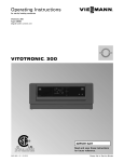
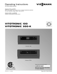
Operating Instructions for use by heating contractor Vitotronic 300, Type GW5B Digital boiler control unit Vitotronic 300-K, Type MW1B Weather-compensated digital cascade control unit VITOTRONIC 300, GW5B VITOTRONIC 300-K, MW1B r r Vitotronic 300, GW5B Vitotronic 300-K Product may not be exactly as shown IMPORTANT Certified as a component part for Viessmann boilers 5693 974 - 01 03/2014 Read and save these instructions for future reference. Please file in Service Binder General Vitotronic 300 GW5B, 300-K MW1B Operating Safety, Installation and Warranty Requirements Please ensure that these instructions are read and understood before commencing installation. Failure to comply with the instructions listed below and details printed in this manual can cause product/property damage, severe personal injury, and/or loss of life. Ensure all requirements below are understood and fulfilled (including detailed information found in manual subsections). For a listing of applicable literature, please see section entitled “Important Regulatory and Safety Requirements”. Warranty Information contained in this and related product documentation must be read and followed. Failure to do so renders the warranty null and void. Licensed professional heating contractor The installation, adjustment, service and maintenance of this equipment must be performed by a licensed professional heating contractor. Please see section entitled “Important Regulatory and Installation Requirements”. 2 Advice to owner Once the installation work is complete, the heating contractor must familiarize the system operator/ ultimate owner with all equipment, as well as safety precautions/requirements, shutdown procedure, and the need for professional service annually before the heating season begins. WARNING Installers must follow local regulations with respect to installation of carbon monoxide detectors. Follow the Viessmann maintenance schedule of the boiler contained in this manual. Operating and Service Documentation It is recommended that all product documentation such as parts lists, operating and service instructions be handed over to the system user for storage. Documentation is to be stored near boiler in a readily accessible location for reference by service personnel. 5693 974 - 01 Product documentation Read all applicable documentation before commencing installation. Store documentation near boiler in a readily accessible location for reference in the future by service personnel. General Vitotronic 300 GW5B, 300-K MW1B Operating Commissioning The commissioning and matching of the control unit to local conditions and building characteristics, as well as instructing the user in the operation of the system, must be carried out by your heating contractor. As the user of new combustion equipment, you may be obliged to notify your local service technician of the installation [check local regulations]. Your local service technician will also inform you [where appropriate] about work he may be required to perform on your combustion equipment (e.g. regular checks, cleaning). Your System is Preset at the Factory The control units are factory-set for central heating and DHW heating: Vitotronic 300-K: “Heating and DHW” Your heating system is therefore ready for use. Central heating Between 06:00 and 22:00 h, the rooms are heated to 68° F (20° C) “Set room temperature” (standard heating mode). Between 22:00 and 06:00 h, the rooms are heated to 37° F (3° C) “Set red. room temp” (reduced heating mode, frost protection). Your heating contractor can make further settings for you during commissioning. You can change any settings individually at any time to suit your requirements (see chapter “Central heating”). DHW heating Between 05:30 and 22:00 h, DHW is heated to 122° F (50° C) “Set DHW temperature”. Any installed DHW circulation pump is on. Between 22:00 and 05:30 h, the DHW cylinder temperature will not be reheated. Any installed DHW circulation pump is off. Your heating contractor can make further settings for you during commissioning. You can change any settings individually at any time to suit your requirements (see chapter “DHW heating”). Frost protection Your boiler, heating circuits and DHW cylinder are protected against frost. Wintertime/summertime changeover This changeover is automatic. Time and date The day and time were set by your heating contractor during commissioning. 5693 974 - 01 Power failure All data is saved if there is a power failure. 3 Table of Contents Vitotronic 300 GW5B, 300-K MW1B Operating Page General Safety, Installation and Warranty Requirements..............2 Commissioning..........................................................3 Your System is Preset at the Factory.............................3 Safety About these Instructions..............................................6 For your Safety......................................................6 Safety Terminology................................................7 Operation Main Controls............................................................8 Where to Find the Controls..........................................8 Controls, Vitotronic 300, GW5B...................................9 How to use the Controls, Vitotronic 300, GW5B..........10 Controls, Vitotronic 300-K.........................................11 Menu, Vitotronic 300-K.............................................12 How to use the Controls, Vitotronic 300-K..................13 Central Heating Starting the Heating System.......................................14 Stopping the Heating System.....................................15 Required Settings (Central Heating).............................16 Selecting a Heating Circuit.........................................16 Setting the Room Temperature...................................17 Setting the Heating Program for Central Heating...........17 Setting the Time Program for Central Heating...............18 Changing the Heating Curve.......................................19 Stopping Central Heating...........................................19 4 Comfort and Energy Saving Functions Selecting Comfort Function “Party Mode”...................20 Selecting Energy Saving Function “Economy Mode”......20 Selecting Energy Saving Function “Holiday Program”....21 DHW Heating Required Settings (DHW Heating)................................22 Setting the DHW Temperature....................................22 Setting the Heating Program for DHW Heating..............22 Setting the Time Program for DHW Heating.................23 Stopping DHW Heating..............................................25 Further Adjustments Selecting the Boiler Sequence.....................................25 Setting the Display Contrast.......................................25 Setting the Display Brightness....................................26 Entering Names for the Heating Circuit........................26 Selecting the Language..............................................27 Setting the Time and Date.........................................27 Setting the Temperature Unit (oC/oF)...........................27 Restoring the Factory Settings....................................28 5693 974 - 01 .. Table of Contents Vitotronic 300 GW5B, 300-K MW1B Operating Page Scanning Options Scanning Information.................................................29 Scanning Service Messages........................................30 Scanning Fault Messages...........................................31 Burner Fault - Remote Reset....................................32 Emissions Test Mode................................................32 Troubleshooting Rooms are Too Cold.................................................33 Rooms are Too Hot...................................................33 There is No Hot Water...............................................34 The DHW is Too Hot.................................................34 “Boiler Status Locked” is Displayed at the Vitotronic 300, GW5B..............................................34 “ ” is Displayed at the Vitotronic 300, GW5B.............35 ““ Flashes and “Fault” is Displayed at the Vitotronic 300, GW5B..............................................35 ““ Flashes and “Fault” is Displayed at the Vitotronic 300-K.......................................................35 “Controls Locked Out”is Displayed at the Vitotronic 300-K......................................................35 “External Hook-up” is Displayed at the Vitotronic 300-K.......................................................35 “Central Control” is Displayed at the Vitotronic 300-K.......................................................35 “External Program” is Displayed at the Vitotronic 300-K.......................................................35 5693 974 - 01 .. Maintenance Maintenance............................................................36 Additional Information Menu Overview, Vitotronic 300, GW5B......................37 Menu Overview, Vitotronic 300-K..............................38 Terminology............................................................41 5 Safety Vitotronic 300 GW5B, 300-K MW1B Operating About these Instructions Take note of all symbols and notations intended to draw attention to potential hazards or important product information. These include “WARNING”, “CAUTION”, and “IMPORTANT”. See below. WARNING Warnings draw your attention to the presence of potential hazards or important product information. Indicates an imminently hazardous situation which, if not avoided, could result in loss of life, serious injury or substantial product/property damage. CAUTION Cautions draw your attention to the presence of potential hazards or important product information. Indicates an imminently hazardous situation which, if not avoided, may result in minor injury or product/ property damage. IMPORTANT Helpful hints for installation, operation or maintenance which pertain to the product. This symbol indicates that additional, pertinent information is to be found. This symbol indicates that other instructions must be referenced. For your Safety H Flue gas smell - Deactivate heating equipment. - Open windows and doors. - Inform your heating contractor. H Working on the equipment All personnel working on the equipment or the heating system must have the proper qualifications and hold all necessary licenses. Ensure main power to equipment, heating system, and all external controls has been deactivated. Close main gas supply valve. Take precautions in all instances to avoid accidental activation of power during service work. 6 H Dangerous conditions - Deactivate main power immediately. - Close gas supply valve. H Maintenance and cleaning Regular inspection and service by a qualified heating contractor is important to the performance of the boiler. Neglected maintenance impacts on warranty; regular inspection ensures clean, environmentally friendly and efficient operation. We recommend a maintenance contract with a qualified heating contractor. H Technical Data Manual - Installation Instruction and Service Instructions - Operating Instructions and User’s Information Manual Additional applicable literature: - Accessory manuals 5693 974 - 01 H Operation Before operating the boiler, make sure you fully understand its method of operation. Your heating contractor should always perform the initial start-up and explain the system. Any warranty is null and void if these instructions are not followed. Vitotronic 300 GW5B, 300-K MW1B Operating For your Safety Safety (continued) CAUTION Follow these safety instructions closely to avoid the risk of injury and damage to property. H Operation Before operating the boiler, make sure you fully understand its method of operation. Your heating contractor should always perform the initial start-up and explain the system. Any warranty is null and void if these instructions are not followed. H Flue gas smell - Deactivate heating equipment. - Open windows and doors. - Inform your heating contractor. H Working on the equipment All personnel working on the equipment or the heating system must have the proper qualifications and hold all necessary licenses. Ensure main power to equipment, heating system, and all external controls has been deactivated. Close main gas supply valve. Take precautions in all instances to avoid accidental activation of power during service work. H Dangerous conditions - Deactivate main power immediately. - Close gas supply valve. H Maintenance and cleaning Regular inspection and service by a qualified heating contractor is important to the performance of the boiler. Neglected maintenance impacts on warranty; regular inspection ensures clean, environmentally friendly and efficient operation. We recommend a maintenance contract with a qualified heating contractor. H Technical Data Manual - Installation Instruction and Service Instructions - Operating Instructions and User’s Information Manual Additional applicable literature: - Accessory manuals If you smell gas H Don’t smoke! Don’t use naked flames or cause sparks (e.g. by switching lights or electrical appliances on and off) H Open windows and doors H Close the gas shut-off valve H Inform your heating engineers/service contractors from outside the building H Observe the safety regulations of your gas supply company (see gas meter) and those of your heating engineers (see start-up or instruction report). In emergencies H Immediately switch off the power supply, e.g. at the separate fuse or power supply disconnect switch (unless there is a smell of gas). H Close the shut-off valves in the oil pipes or close the gas shut-off valve, whichever applicable. H Use suitable extinguishers in the event of fire. Installation of additional components The installation of additional components which have not been tested together with the boiler can adversely affect the function and performance of the boiler. Our warranty does not cover and we accept no liability for damage attributable to the installation of such components. Boiler room conditions H Do not use a room in which the air is polluted by halogenated hydro-carbons (e.g. as contained in aerosols, paints, solvents and cleaning agents) H Do not use a room subject to high levels of dust H Do not use a room subject to permanently high humidity H The room should be frost-protected H Max. ambient temperature 95° F (35° C). H Provide good ventilation and do not close or obstruct vents (if installed). This symbol indicates a reference to other instructions which must be observed. Safety Terminology Take note of all symbols and notations intended to draw attention to potential hazards or important product information. These include ”WARNING” and ”CAUTION”. See below. WARNING Indicates an imminently hazardous situation which, if not avoided, could result in substantial product / property damage, serious injury or loss of life. 5693 974 - 01 CAUTION Indicates an imminently hazardous situation which, if not avoided, may result in minor injury or product / property damage. 7 Operation Vitotronic 300 GW5B, 300-K MW1B Operating The Main Controls The settings required for operating your heating system are made on the Vitotronic 300, GW5B of each boiler and on the Vitotronic 300-K. If the system is equipped with remote controls, you can also use the remote controls for some of the settings. See Operating Instructions for the remote control The control unit is behind the hinged cover. The hinged cover is opened by pulling the top gently downwards towards you. You must close the hinged cover again after use. Where to Find the Controls Each boiler is equipped with its own control unit for constant temperature operation. These control units are regulated by a higher weathercompensated cascade control unit. H Control unit for cascade operation on the boiler: Vitotronic 300, GW5B H Higher weather-compensated cascade control unit: Vitotronic 300-K You can change all settings for your heating system centrally at the control unit programming unit. You may also make such changes at the remote control units, if your system is equipped with such units. Remote control operating instructions 8 5693 974 - 01 The settings at the Vitotronic 300, GW5B and Vitotronic 300-K are described in these operating instructions. You do not need the operating instructions provided with these control units. Operation Vitotronic 300 GW5B, 300-K MW1B Operating Controls, Vitotronic 300, GW5B Opening the control unit Vitotronic 300, GW5B The programming unit is located behind the flap. To open, pull the flap from the top edge forward. A Cover flap Programming unit 5693 974 - 01 Takes you to the previous step in the menu or cancels a setting that has been started. Cursor keys To scroll through the menu or to set values. OK Confirms your selection or saves the setting. ? No function. Enables you to call up the menu for settings and scanning. 9 Operation Vitotronic 300 GW5B, 300-K MW1B Operating How to Use the Controls, Vitotronic 300, GW5B In multi boiler systems, each Vitotronic 300, GW5B indicates the boiler number on the standard display. The example shows the boiler water temperature as indicated by boiler 4. Note: If a boiler is not operational, the following appears in the display of the corresponding control unit: Locked Disabled . Press This takes you to the menu for settings and scanning. Symbols These symbols are not always displayed, but appear subject to the system version and the operating state. Flashing displays indicate that modifications can be made. Menu S Information Further adjustments Emissions test mode Heating program 9 Standby mode with frost protection monitoring The boiler is available to the cascade control unit for heat production. Messages u Service message The service interval has expired. Fault message Displays 10 Burner in operation 5693 974 - 01 A Operation Vitotronic 300 GW5B, 300-K MW1B Operating Controls, Vitotronic 300-K Opening the control unit The programming unit is located behind the flap. To open, pull the flap from the top edge forward. A Cover flap Programming unit Menu “Help” You can view a short guide giving an explanation of the controls and information about heating circuit selection (see page 16). Call up the short guide as follows: H If the screen saver is active (see page 13): Press OK akes you to the previous step in the menu or T cancels a setting that has been started. H From anywhere in the menu: Press until the standard menu is shown (see the following chapter). Press? Cursor keys To scroll through the menu or to set values. OK Confirms your selection or saves the setting. ? To call up additional information regarding the selected menu option. 5693 974 - 01 Calls up the extended menu. 11 Operation Vitotronic 300 GW5B, 300-K MW1B Operating Menu, Vitotronic 300-K There are two control levels available, the “Standard menu” and the “Extended menu”. The menu overview can be found on page 39. Standard menu Call up the standard menu as follows: H If the screen saver is active (see page 13) Press OK. H From anywhere in the menu: until the standard menu appears. Keep pressing In the standard menu, the number of boilers installed in the heating system is shown in a specific order (boiler sequence). You can change the boiler sequence (see page 25). The meanings of the icons are as follows: H Solid white: The boiler has been enabled by the cascade control unit and is operating (boiler 3 in this example). H Solid grey: The boiler is available for generating heat but has not been enabled by the cascade control unit (boilers 2 and 4 in this example). H Solid black and crossed out: This boiler is not available for heat production (boiler 1 in this example). Note: 2 minutes after any setting has been made, the display automatically reverts to the standard menu. Extended menu Call up the extended menu as follows: H If the screen saver is active (see page 13): Press OK and then . H From anywhere in the menu: Press . 12 5693 974 - 01 A Dialogue line Note: Your heating contractor can block the use of the extended menu. In this case, you can only scan fault messages. Operation Vitotronic 300 GW5B, 300-K MW1B Operating How to Use the Controls, Vitotronic 300-K The screen saver will become active if you have not adjusted any settings on the programming unit for a few minutes. The display brightness is reduced. 1. Press OK. This takes you to the standard menu. 2. Press . This takes you to the extended menu (see page 38). The selected menu option is highlighted in white. The dialogue line A (see previous page) then shows the necessary instructions. 5693 974 - 01 The following diagram shows how to make settings with different dialogue lines, using the set room temperature setting as an example. 13 Central Heating Vitotronic 300 GW5B, 300-K MW1B Operating Starting the Heating System Vitotronic 300, type GW5B Controls with cover flap open Legend A ON indicator (green) B Fault indicator (red) C Emissions test switch (only for service purposes) D ON/OFF switch E Fuses Vitotronic 300-K, type MW1B Controls with cover flap open 14 1. Check the heating system pressure. 2. Check that the ventilation apertures of the installation room are open and unrestricted. Note: With open flue operation, the combustion air is drawn from the installation room. 3. 4. 5. Open the gas shut-off valve. Switch ON the power supply, e.g. in breaker panel. Switch ON the ON/OFF switches at all Vitotronic 300, GW5B and at the Vitotronic 300-K (see chapter “Controls”). After a short time, the following is shown on the display: H Vitotronic 300, GW5B: the standard display (see page 10) H Vitotronic 300-K: the standard menu (see page 38) The green ON indicator illuminates. Your heating system and, if installed, your remote control units are now ready to operate. Note: On every Vitotronic 300, GW5B, “ “ must be selected, otherwise the Vitotronic 300-K cannot use the corresponding boiler to produce heat. 5693 974 - 01 Legend A ON indicator (green) B Fault indicator (red) C Emissions test switch (only for service purposes) D ON/OFF switch E Fuse Central Heating Vitotronic 300 GW5B, 300-K MW1B Operating Stopping the Heating System With frost protection monitoring At the Vitotronic 300-K, select the heating program “Standby mode” for every heating circuit. H No central heating. H No DHW heating. H Frost protection for the heating circuits and the DHW tank is active. Extended menu 1. 2. “Heating” 3. Select the heating circuit, if necessary (see page 16). 4. “Heating program” 5. “Standby mode” (frost protection monitoring) Note: The circulation pumps are briefly started every 24 hours to prevent them from seizing up. Ending the heating program “Standby mode” Select another heating program. Stopping individual boilers at the relevant Vitotronic 300, GW5B Press the following keys: 1. From the main screen press 2. Use 3. press OK to confirm. Y. to select “9“ Without frost protection monitoring (shutdown) 1. Switch OFF the ON/OFF switches at all Vitotronic 300, GW5B and Vitotronic 300-K (see chapter “Controls”). 2. Close the shut-off valves in the oil lines (at the tank and filter) or close the gas shut-off valve. 3. Isolate the heating system from its main power supply, e.g. at a separate MCB/fuse or a mains isolator. 4. Where outside temperatures of below 37° F (3° C) are anticipated, please take suitable measures to protect the heating system against frost. If necessary, contact your heating contractor. Information on a prolonged shutdown H Circulation pumps may seize up as they are not supplied with power. 5693 974 - 01 H Vitotronic 300-K: It may be necessary to reset the date and time (see page 27). 15 Central Heating Vitotronic 300 GW5B, 300-K MW1B Operating Required Settings (Central Heating) Make the settings for central heating at the Vitotronic 300-K. If you want central heating, check the following points: H Have you selected the heating circuit? For settings, see the next chapter. H Have you set the required room temperature? For settings, see page 17. H Have you selected the correct heating program? For settings, see page 17. H Have you set the required time program? For settings, see page 18. Selecting a Heating Circuit Extended menu 1. 2. “Heating” The heating of all rooms can, if necessary, be split over several heating circuits. H In the case of heating systems with several heating circuits, for all central heating settings, first select the heating circuit where you want to make a change. H This selection is not possible in heating systems with only one heating circuit. Example: H “Heating circuit 1” is the heating circuit for the offices on the ground floor. 3. for the required heating circuit. H “Heating circuit 2” is the heating circuit for the offices on the first floor. The heating circuits are marked at the factory as “Heating circuit 1” (HC1), “Heating circuit 2” (HC2) and “Heating circuit 3” (HC3). 16 5693 974 - 01 If you or your heating contractor have renamed the heating circuits (e.g. as “Ground floor” etc.), the name is displayed instead of “Heating circuit ...” (see page 26). Central Heating Vitotronic 300 GW5B, 300-K MW1B Operating Setting the Room Temperature Setting the room temperature for standard heating mode Factory setting: 68° F (20° C) Extended menu 1. 2. “Heating” 3. Select the heating circuit, if necessary (see page 16). 4. “Set room temperature” 5. Set the required value. Setting the room temperature for reduced heating mode (night setback) Factory setting: 37° F (3° C) Extended menu 1. 2. “Heating” 3. Select the heating circuit, if necessary (see page 16). 4. “Set red. room temp” 5. Set the required value. The rooms are heated to this temperature: H Between the time phases for standard heating mode (see page 18). H In the holiday program (see page 21). Setting the Heating Program for Central Heating Factory setting: “Heating and DHW” Extended menu 1. 2. “Heating” 3. Select the heating circuit, if necessary (see page 16). 4. “Heating program” 5. “Heating and DHW” H The rooms of the selected heating circuit are heated in accordance with the room temperature and time program settings. 5693 974 - 01 H DHW is reheated in accordance with the set DHW temperature and time program (see chapter “DHW heating”). 17 Central Heating Vitotronic 300 GW5B, 300-K MW1B Operating Setting the Time Program for Central Heating H The time program for central heating is made up of time phases. One time phase from 6:00 to 22:00 h for every day of the week is set at the factory. H You can set the time program individually, to be the same for every day of the week or different: You can select up to 4 time phases per day for standard heating mode. Set the start and end points for each time phase. Between these time phases, the rooms are heated with the reduced room temperature (see chapter “Setting the room temperature for reduced heating mode”). H When setting, bear in mind that your heating system requires some time to heat the rooms to the required temperature. H In the extended menu, you can scan the current time program under “Information” (see chapter “Scanning information”, “Heating circuit ...” group). Extended menu: 1. Example shown: H Time program for Monday to Friday (“Mo-Fr”) H Time phase !: From 05:00 to 08:30 h 2. “Heating” 3. Select the heating circuit if necessary. 4. “Heating time program” 5. Select part of the week or a day. 6. Select the time phase !, ?, § or $. 7. Set the start and end points for the relevant time phase. 8. Press to exit the menu. Note: If you want to terminate a time phase setting process prematurely, keep pressing until the required display appears. H Time phase ?: From 16:30 to 23:00 h Example: You want to set the same time program for every day except Monday: Select the period “Monday–Sunday” and set the time program. Then select “Monday” and set the time program for this. Deleting a time phase 18 5693 974 - 01 Set the time for the end point to the same time that was set for the start point. The display shows the selected time phase ”- - : - -”. Central Heating Vitotronic 300 GW5B, 300-K MW1B Operating Changing the Heating Curve Your system’s heating characteristics are affected by the slope and the shift of the selected heating curve. Further information about the heating curve can be found under “Terminology” on page 41. Factory setting: H Slope: 1.4 H Heating curve shift: 0 H Standard room temperature (set value): 68° F (20º C) H Reduced room temperature (set value): 37° F (3º C) Extended menu: 1. 2. “Heating” 3. Select the heating circuit, if necessary (see page 16). 4. “Heating curve” 5. “Slope” or “Shift” Note: Tips on when and how to change the heating curve slope and shift are displayed by pressing . Example: 6. ? Set the required value. Change the heating curve slope to 1.5. A graph clearly shows the change in the heating curve as soon as you alter the value for slope or shift. Depending on various outside temperatures (shown on the horizontal axis), the assigned set supply temperatures for the heating circuit are highlighted white. Stopping Central Heating Extended menu 5693 974 - 01 1. 2. “Heating” 3. Select the heating circuit, if necessary (see page 16). 4. “Heating program” 5. “Only DHW” (summer mode, no central heating) or “Standby mode” (frost protection monitoring) 19 Comfort and Energy Saving Functions Vitotronic 300 GW5B, 300-K MW1B Operating Selecting Comfort Function “Party Mode” Make the settings for the comfort function at the Vitotronic 300-K. With this function, you can change the room temperature for several hours, e.g. if guests unexpectedly stay longer in the evening. You do not have to change any existing control settings. With this function, DHW is reheated to the selected set temperature. Extended menu 1. 2. “Heating” 3. Select the heating circuit, if necessary (see page 16). 4. “Party mode” 5. Set the room temperature required during party mode. H The rooms are heated to the required temperature. H DHW is reheated to the selected set temperature. H The DHW circulation pump is switched ON (if installed). Ending party mode H Automatically when the system switches to standard heating mode in accordance with the time program. or H In the extended menu, set “Party mode” to “OFF”. Selecting Energy Saving Function “Economy Mode” Make the settings for the energy saving function at the Vitotronic 300-K. To save energy, you can reduce the room temperature in standard heating mode. For example, if you leave your home for a few hours. Extended menu 1. 2. “Heating” 3. Select the heating circuit, if necessary (see page 16). 4. “Economy mode” Ending economy mode H Automatically when the system switches to reduced heating mode in accordance with the time program. or 20 5693 974 - 01 H In the extended menu, set “Economy mode” to “OFF”. Comfort and Energy Saving Functions Vitotronic 300 GW5B, 300-K MW1B Operating Selecting Energy Saving Function “Holiday Program” To save energy, for example over long holidays, you can activate the “Holiday program”. Make the settings for this energy saving function at the Vitotronic 300-K. Note: The control unit is set up so that the holiday program applies to all heating circuits. If you want to make changes, contact your local heating contractor. The holiday program has the following effect on the heating circuits and DHW heating: H Central heating: - For heating circuits in the heating program “Heating and DHW”: In these heating circuits, the rooms are heated to the selected reduced room temperature (see page 20). - For heating circuits in the heating program “Only DHW”: No central heating in these heating circuits. If the heating program “Only DHW” is selected for all heating circuits, frost protection monitoring is only enabled for the boiler and DHW tank. H DHW heating: DHW heating is switched OFF; frost protection for the DHW tank is active. The holiday program starts at 00:00 h the day following your departure and ends at 00:00 h on the day of your return. This means the selected time program is active on the days of departure and return. Extended menu: 1. 2. “Heating” 3. “Holiday program” 4. Set the required departure and return dates. Display in the extended menu In the extended menu, you can scan the selected holiday program under “Information” (see chapter “Scanning information”, “Heating circuit ...” group). Terminating or deleting a holiday program Extended menu 5693 974 - 01 1. 2. “Heating” 3. “Holiday program” 4. “Delete program” 21 DHW Heating Vitotronic 300 GW5B, 300-K MW1B Operating Required Settings (DHW Heating) Make the settings for DHW heating at the Vitotronic 300-K. If you want DHW heating, check the following points: H Have you set the required DHW temperature? For settings, see the next chapter. H Have you selected the correct heating program? For settings, see page 22. H Have you set the required time program? For settings, see page 23. Note: The control unit is set up so that DHW heating applies to all heating circuits. If you want to make changes, contact your local heating contractor. Setting the DHW Temperature Extended menu 1. 2. “DHW” 3. “Set DHW temperature” 4. Set the required value. Setting the Heating Program for DHW Heating Extended menu 22 2. “Heating” 3. Select the heating circuit, if necessary (see page 16). 4. “Heating program” 5. “Heating and DHW” (with central heating) or “Only DHW” (summer mode, no central heating) 5693 974 - 01 1. DHW Heating Vitotronic 300 GW5B, 300-K MW1B Operating Setting the Time Program for DHW Heating H The time program for DHW heating is made up of time phases. One time phase from 5:30 to 22:00 h for every day of the week is set at the factory. H Automatic mode is set at the factory for DHW heating. This means that, in standard heating mode, the DHW is reheated to the set temperature. To ensure that hot water is available at the start of standard heating mode, the time phase for DHW heating begins automatically half an hour earlier than the time phase for standard heating mode. H If you don’t want the automatic mode, you can select up to 4 individual time phases per day for DHW heating, which can be the same for every day of the week or different. Set the start and end points for each time phase. H When setting, bear in mind that your heating system requires some time to heat the DHW to the required temperature. H In the “Extended menu”, you can scan the current time program under “Information” (see chapter “Scanning information”, “DHW” group). Extended Menu 1. 2. “DHW” 3. “DHW time prog” 4. “Individual” 5. Select part of the week or a day. 6. Select the time phase !, ?, § or $. 7. Set the start and end points for the relevant time phase. Example shown: 8. Press H Time program for Monday to Friday (“Mo-Fr”) Note: If you want to terminate a time phase setting process prematurely, keep pressing until the required display appears. H Time phase !: From 04:30 to 06:30 h H Time phase ?: From 15:30 to 20:30 h to exit the menu. Deleting a time phase Set the time for the end point to the same time that was set for the start point. The display shows the selected time phase ”- - : - -”. DHW heating once, no longer in the time program Note: The heating program “Heating and DHW” or “Only DHW” must be set for at least one system heating circuit. Extended menu 5693 974 - 01 Example: You want to set the same time program for every day except Monday: Select the period “Monday–Sunday” and set the time program. Then select “Monday” and set the time program for this. 1. 2. “Heating” 3. “Party mode” 4. Disable “Party mode” again with “OFF” to prevent unintentional central heating with standard room temperature. 23 DHW Heating Vitotronic 300 GW5B, 300-K MW1B Operating Setting the Time Program for DHW Heating (continued) Heating system with DHW circulation pump For further information about the DHW circulation pump, see chapter “Terminology”. H Automatic mode is set for the DHW circulation pump time program. In other words, the DHW circulation pump operates in parallel to the DHW heating time program. H If you don’t want the automatic mode, you can select up to 4 individual time phases per day for the DHW circulation pump, which can be the same for every day of the week or different. Set the start and end points for each time phase. H In the “Information” menu, you can scan the current time program (see chapter “Scanning information”, “DHW” group). Note: Activating the DHW circulation pump is only advisable for those times when DHW is actually drawn. Extended menu: 1. 2. “DHW” 3. “DHW circ time prog” 4. “Individual” 5. Select part of the week or a day. 6. Select the time phase !, ?, § or $. 7. Set the start and end points for the relevant time phase. 8. Press to exit the menu. Note: If you want to terminate a time phase setting process prematurely, keep pressing until the required display appears. Deleting a time phase 24 5693 974 - 01 Set the time for the end point to the same time that was set for the start point. The display shows the selected time phase ”- - : - -”. DHW Heating/ Further Adjustments Vitotronic 300 GW5B, 300-K MW1B Operating Stopping DHW Heating You do not want to have DHW or heat your rooms. Extended menu 1. 2. Select the heating circuit, if necessary (see page 16). 3. “Heating” 4. “Heating program” 5. “Standby mode” (frost protection monitoring) You do not want DHW, but do want to heat the rooms. Extended menu 1. 2. Select the heating circuit, if necessary (see page 16). 3. “Heating” 4. “Heating program” 5. “Heating and DHW” 6. until the menu is displayed. 7. “DHW” 8. “Set DHW temperature” 9. Select 50° F (10° C). Selecting the Boiler Sequence Only for the Vitotronic 300-K. Subject to the parameters set and internal control calculations, the control unit offers various boiler sequences. You can change the boiler sequence. Extended menu 1. 2. “Boiler sequence” 3. Set the required boiler sequence and confirm with OK. Setting the Display Contrast Only for the Vitotronic 300-K. Extended menu 5693 974 - 01 1. 2. “Settings” 3. “Contrast” 4. Set the required contrast. 25 Further Adjustments Vitotronic 300 GW5B, 300-K MW1B Operating Setting the Display Brightness Only for the Vitotronic 300-K. If you would like the texts in the menu to be more clearly legible, change the brightness for “Control”. You can also alter the screen saver brightness. Extended menu 1. 2. “Settings” 3. “Brightness” 4. “Control” or “Screen saver” 5. Set the required brightness. Entering Names for the Heating Circuits Only for the Vitotronic 300-K. You can give heating circuits 1, 2 and 3 (“HC1”, “HC2” and “HC3”) individual names. The abbreviations “HC1”, “HC2” and “HC3” will be retained. Extended menu 1. 2. “Settings” 3. “Name for heating circ.” 4. “Heating circuit 1”, “Heating circuit 2 or “Heating circuit 3” 5. “Change?” 6. You can select the required symbol with 7. 8. . takes you to the next character. Press OK to accept all entered characters at once and simultaneously exit this menu. Note: The entered term is deleted with “Reset?”; “Heating circuit 1” will then be shown again. Example: Name for “Heating circuit 1”: Ground floor 26 5693 974 - 01 The menu shows “Ground floor” for “Heating circuit 1”. Further Adjustments Vitotronic 300 GW5B, 300-K MW1B Operating Selecting the Language Only for the Vitotronic 300-K. Extended menu 1. 2. “Settings” 3. “Language” 4. Select the required language. Setting the Time and Date Only for the Vitotronic 300-K. The time and date are factory-set. If your heating system has been shut down for a long time, it may be necessary to set the time and date. Extended menu 1. 2. “Settings” 3. “Time/Date” 4. Set the time and date. Setting the Temperature Unit (°C/°F) Vitotronic 300-K Factory setting: °C Press the following keys: 1. 2. scroll to “settings”, select with OK. 3. scroll to temperature unit, select with OK. 4. select “°C” or “°F”, select with OK. 5. to return to main screen. Vitotronic 300-K Factory setting: °C Extended menu 5693 974 - 01 1. 2. Settings” 3. “Temperature unit” 4. Select the temperature unit “°C” or “°F”. 27 Further Adjustments Vitotronic 300 GW5B, 300-K MW1B Operating Restoring Factory Settings Vitotronic 300, GW5B You can simultaneously reset all changed values to the factory settings. Press the following keys: 1. 2. scroll to “inform”, select with OK. 3. scroll to “reset data”, select with OK. 4. select “all data”, select with OK. 5. select “yes”, select with OK. 6. to return to main screen. Factory settings: H Heating program: “ “ H Temperature unit: °F (°C) Vitotronic 300-K You can reset the factory settings of all modified values for each heating circuit separately. Extended menu 1. 2. “Settings” 3. “Standard setting” 4. “Heating circuit 1”, “Heating circuit 2” or “Heating circuit 3” The following settings and values are reset: H Set room temperature for standard heating mode (“Set room temperature”). H Set room temperature for reduced heating mode (“Set red. room temp”). H Heating program (“Heating program”). H Set DHW temperature (“Set DHW temperature”). H Time program for central heating (“Heating time program”). H Time program for DHW heating (“DHW time prog”). H Time program for DHW circulation pump (“DHW circ time prog”). H Heating curve slope (“Slope”) and shift (“Shift”). 28 5693 974 - 01 Party mode, economy mode and holiday program are deleted. Scanning Options Vitotronic 300 GW5B, 300-K MW1B Operating Scanning Information Vitotronic 300, GW5B — scans for every boiler Subject to the connected components and settings made, you can scan current temperatures and operating conditions. Press the following keys: 1. and OK together until “service” appears. 2. until “diagnosis” appears. 3. until “general” appears. 4. for the required information and press OK. 5. to return to main screen. Note: Information number is displayed, indicating the current boiler water temperature. Note: The scan mode terminates automatically after 30 min. or if you press . Vitotronic 300-K — scans for the heating system Subject to the connected components and settings made, you can scan current temperatures and operating conditions. Scanning in conjunction with solar thermal systems Extended menu 1. 2. “Solar energy” The solar energy yield for the past 7 days is displayed on a graph. The flashing line on the graph indicates that the current day is not yet over. Note: Further scanning options, e.g. for the solar circuit pump hours run, can be found in the extended menu under “Information” in the “Solar” group. The extended menu splits the information into groups: H “General” H “Heating circuit 1” H “Heating circuit 2” H “Heating circuit 3” H “DHW” H “Solar” H “Reset data” Note: If heating circuits have been given names, the name is displayed (see chapter “Entering names for the heating circuits”). For detailed scanning options for the individual groups, see chapter “Scanning options in the extended menu”. Extended menu 1. 2. “Information” 3. Select the group. 4. Select the required scan. Resetting data to 0 You can reset the following data: H In conjunction with a solar thermal system: Solar energy yield and hours run for the solar circuit pump and output 22. H All the above data simultaneously. Extended menu 5693 974 - 01 1. 2. “Information” 3. “Reset data” 29 Scanning Options Vitotronic 300 GW5B, 300-K MW1B Operating Scanning Service Messages Vitotronic 300, GW5B If your heating system is due for a service, the symbol “ “ flashes in the display, and “Service” appears. 1. You can call up the cause of the fault with OK. 2. Pressing is due. 3. If you want to acknowledge the service message, follow the instructions in the menu. Contact your local heating contractor. The service message is transferred to the menu. ? calls up information on the service that Display in the standard menu Display in the extended menu Note: If the service can only be carried out at a later date, the service message is displayed again the following Monday. Calling up an acknowledged service message Extended menu 1. 2. “Service” Vitotronic 300-K 30 5693 974 - 01 No service interval can be set at the Vitotronic 300-K. No service message is therefore shown. Scanning Options Vitotronic 300 GW5B, 300-K MW1B Operating Scanning Fault Messages Vitotronic 300, GW5B and 300-K If any faults have occurred in your heating system, the symbol ““ flashes on the display, and “Fault” is shown. The red fault indicator also flashes (see chapter “Starting the heating system”). 1. You can call up the cause of the fault with OK. 2. Pressing ? calls up information on the heating system functions. Tips on which measures you can take yourself before notifying your heating contractor are also displayed. 3. Make a note of the cause of the fault and the fault code to the right of it. In this example: “Outside temp sensor 18” and “Fault A2” This enables the heating contractor to be better prepared for the service call and may save additional travelling costs. 4. If you want to acknowledge the fault message, follow the instructions in the menu. The fault message is transferred to the menu. Note: H If you have connected up signalling equipment (e.g. a buzzer) for fault messages, this is deactivated when the fault message is acknowledged. H If the fault can only be rectified at a later date, the fault message will be displayed again the next day and the signalling equipment will be switched on again. Calling up an acknowledged fault message Extended menu 1. 5693 974 - 01 2. “Fault” 31 Scanning Options Vitotronic 300 GW5B, 300-K MW1B Operating Burner Fault - Remote Reset Vitotronic 300, GW5B Note: The following applies to control serial number 7537696 only. When a combustion controller fault appears, scan the fault message (see page 28). Resolve the fault condition. Refer to the Service Instructions. Once the fault is resolved, continue with the following; 1. During locking the display will read ‘Combustion controller locked out’. To continue press OK. 2. To reset the burner press OK. 3. The display will return to normal operation once the burner has been reset. Emissions Test Mode Emissions test mode for testing flue gas with boiler water temperature raised briefly. This test mode should only be activated by your service technician during the annual inspection. Test mode must be activated at the Vitotronic 300, GW5B of the boiler to be tested and also, for heat transfer, at the Vitotronic 300-K cascade control unit. Vitotronic 300, GW5B and Vitotronic 300-K Move the emissions test switch on both control units (see chapter “Controls”) to position S. The following functions are activated: H Burner is started. Note: Burner start-up can be delayed, e.g. through fuel oil preheating. H All pumps are started. H Mixing valve remains set to control function H The temperature controller regulates the boiler water temperature. Set the emissions test switch to position a or Close the cover flap (see page 9). 32 5693 974 - 01 Ending emissions test mode Troubleshooting Vitotronic 300 GW5B, 300-K MW1B Operating Rooms are Too Cold Cause The heating system is switched off Remedy H Turn the ON/OFF switches (see chapter “Controls”) at all control units ON. H Switch ON the mains isolator, if installed (outside the boiler room). Control unit or remote control incorrectly set. H Check the fuse/MCB in the power distribution board (main domestic fuse/ MCB), and reset/replace if required. Check settings and correct if required: H At every Vitotronic 300: GW5B “ “ must be set (see page 10). H At the Vitotronic 300-K: - “Heating and DHW” must be selected for the heating circuit (see page 17). - Room temperature (see page 17). - Time (see page 27). - Time program (see page 18). - Heating curve (see page 19) H Check the settings at the remote control (if available). Separate operating instructions Only when operating with DHW heating: DHW priority is enabled. Slab curing function for slab curing drying is active. (Not used) No fuel. “Fault” is displayed at the Vitotronic 300-K, and the red fault indicator flashes (see chapter “Controls”). Symbol ““ is displayed by the Vitotronic 300, GW5B. Wait until the DHW tank has been heated up. Wait until the slab curing drying time has elapsed. (Not used) H With fuel oil or LPG: Check the fuel reserves and re-order if required. - With natural gas: Open the gas shut-off valve or enquire with your gas supply utility if required. Scan the type of fault, make a note of the fault code and acknowledge the message (see page 31). Contact your local heating contractor if required. Scan the type of fault, make a note of the fault code and acknowledge the message (see page 31). If necessary, notify your heating contractor. Rooms are Too Hot Cause Control unit or remote control incorrectly set. Remedy Check settings and correct if required: - At the Vitotronic 300-K: - Room temperature (see page 17). - Time (see page 27). - Time program (see page 18). - Heating curve (see page 19). - Check the settings at the remote control (if available). Separate operating instructions 5693 974 - 01 “Fault” is displayed at the Vitotronic 300-K, and the red fault indicator flashes (see chapter “Controls”). Symbol ““ is displayed by the Vitotronic 300, GW5B. Emissions test mode is enabled Scan the type of fault, make a note of the fault code and acknowledge the message (see page 31). Contact your local heating contractor if required. Scan the type of fault, make a note of the fault code and acknowledge the message (see page 31). If necessary, notify your heating contractor. Terminate emissions test mode (see page 32). 33 Troubleshooting Vitotronic 300 GW5B, 300-K MW1B Operating There is No Hot Water Cause Remedy The heating system is switched off. - Turn the ON/OFF switches (see chapter “Controls”) at all control units ON. - Switch ON the mains isolator, if installed (outside the boiler room). - Check the fuse/MCB in the power distribution board (main domestic fuse/ MCB), and reset/replace if required. Control unit or remote control incorrectly set. Check settings and correct if required: - At every Vitotronic 300: GW5B “ “ must be set (see page 10). - At the Vitotronic 300-K: - DHW heating must be enabled (see page 22). - DHW temperature (see page 22). - Time (see page 27). - Time program (see page 23). - Check the settings at the remote control (if available). Separate operating instructions No fuel. See page 33. “Fault” is displayed at the Vitotronic 300-K, and the red fault indicator flashes (see chapter “Controls”). Scan the type of fault, make a note of the fault code and acknowledge the message (see page 31). If necessary, notify your heating contractor. Symbol ““ is displayed by the Vitotronic 300, GW5B. Scan the type of fault, make a note of the fault code and acknowledge the message (see page 31). If necessary, notify your heating contractor. The DHW is Too Hot Cause Remedy Control unit incorrectly adjusted. Check and correct the DHW temperature, if required (see page 22). DHW heating is carried out by the solar thermal system. Check and correct settings, if required, at the solar control unit. Separate operating instructions Emissions test mode is enabled. Terminate emissions test mode (see page 32). 34 Cause Remedy The heating program is enabled or the boiler is shut down externally. Set the heating program . If necessary, notify your heating contractor. 5693 974 - 01 “Boiler Status Locked” is Displayed at the Vitotronic 300, GW5B Troubleshooting Vitotronic 300 GW5B, 300-K MW1B Operating “ ” is Displayed at the Vitotronic 300, GW5B Cause Remedy The time for a service, as specified by your heating contractor, has arrived. Proceed as described on page 30. “” Flashes and “Fault” is Displayed at the Vitotronic 300, GW5B Cause Remedy Heating system fault. Proceed as described on page 33. “” Flashes and “Fault” is Displayed at the Vitotronic 300-K Cause Remedy Heating system fault. Proceed as described on page 33. “Controls Locked Out” is Displayed at the Vitotronic 300-K Cause Remedy This function is disabled. Your heating contractor can lift this block. “External Hook-up” is Displayed at the Vitotronic 300-K Cause Remedy The heating program selected at the control unit was changed over by an external switching device. No remedy required. “Central Control” is Displayed at the Vitotronic 300-K Cause Remedy The settings of the heating and holiday programs will be adopted from the heating circuit for which “Central control” has been selected. - “External Program” is Displayed at the Vitotronic 300-K Cause Remedy 5693 974 - 01 The heating program set at the control unit was changed You can change the heating program. over by the Vitocom communication interface. 35 Maintenance Vitotronic 300 GW5B, 300-K MW1B Operating Maintenance Cleaning All equipment can be cleaned with a commercially available domestic cleaning agent (non-scouring). You can clean the front of the programming unit with a microfibre cloth. Inspection and maintenance Regular maintenance ensures trouble free, energy efficient, environmentally responsible and safe heating. Your heating system must be serviced by an authorised contractor at least every 2 years. For this, we advise you to arrange an inspection and maintenance contract with your local heating contractor. Boiler Increasing boiler contamination raises the flue gas temperature and thereby increases energy losses. For that reason, all boilers should be cleaned annually. DHW tank (if installed) Maintenance and cleaning should be carried out no later than two years after commissioning and thereafter as required. Only a qualified heating contractor should clean the inside of a DHW tank and the DHW connections. Refill any water treatment equipment (e.g. a lock or injection system) in good time, if such equipment is installed in the cold water supply of the DHW tank. Observe the manufacturer’s instructions. Additionally for a Vitocell 100: We recommend that the correct function of the sacrificial anode is checked annually by your heating contractor. The anode function can be checked without interrupting the system operation. The heating contractor will check the ground current with an anode tester. Safety valve (DHW tank) The safety valve function should be checked every six months by venting, either by the system user or the local heating contractor. The valve seat may become contaminated (see the valve manufacturer’s instructions). Potable water filter (if installed) To maintain high hygienic standards, proceed as follows: H Replace filter element on non-back flushing filters every six months (visual inspection every two months). H On back flushing filters, back flush every two months. Damaged connecting cables 36 5693 974 - 01 If connecting cables of the appliance or externally installed electrical accessories are damaged, replace them with special connecting cables. Replace only with Viessmann cables. Contact your local heating contractor. Vitotronic 300 GW5B, 300-K MW1B Operating Additional Information Menu Overview Vitotronic 300, GW5B Standard menu Information Settings General Reset data See detailed scan options Language DE Contrast Brightness Temperature unit Extended menu General “Boiler temperature” “Flue gas temp” “Output 20” “Output 29” “Output 52” Scanning options in the extended menu Note: Subject to the actual heating system equipment level, not all of the scans listed here may be available. You can scan more details on information marked with . “Burner” “Operating hours” “Compiled fault” “Participant no.” 5693 974 - 01 “Input ext. EA1” 37 Additional Information Vitotronic 300 GW5B, 300-K MW1B Operating Menu Overview Vitotronic 300-K Extended menu Boiler sequence Heating DHW Solar energy Test mode Set DHW temperature DHW time prog DHW circ time prog Settings General Heating circuit 1 HC1 Heating circuit 2 HC2 Heating circuit 3 HC3 DHW Solar Reset data Time / Date Language DE Contrast Brightness Temperature unit Name for heating circ. Standard menu Standard setting 38 Detailed scan options: see page 39 Party mode Economy mode Set room temperature Set reduced room temp Heating program Heating time program Holiday program Heating curve Heating and DHW Only DHW Standby mode 5693 974 - 01 Information Additional Information Vitotronic 300 GW5B, 300-K MW1B Operating Menu Overview Vitotronic 300-K (continued) Scanning options in the extended menu Note: Subject to the actual heating system equipment level, not all of the scans listed here may be available. You can scan more details on information marked with . General Heating circuit 1 (HC1) “Outside temp” “Heating program” “Boiler sequence” - “Slab curing function” (Not used) “Boiler temperature” Boiler - “External hook-up” “Sensor 17 A” - “Holiday program” “Sensor 17 B” - “External program” “Common supply temp” - “Party mode” “Output 20” - “Economy mode” “Output 29” - “Heating and DHW” “Output 52” - “only DHW” “Accessories pump” - “Standby mode” “Block 3rd pty dev” “Central fault mess” “Operating status:” “Participant no.” - “Standard heating mode” “Input ext. EA1” - “Reduced mode” “Time” - “Standby mode” “Date” “Time program” “Set room temperature” “Room temperature” “Set red. room temp” “Set ext. room temp” “Set party temp” “Slope” “Shift” “Heating pump” 5693 974 - 01 “Holiday program” 39 Additional Information Vitotronic 300 GW5B, 300-K MW1B Operating Menu Overview Vitotronic 300-K (continued) Heating circuit 2, 3 (HC2, HC3) DHW “Heating program” “DHW time prog” - “Slab curing function” (Not used) “DHW circ time prog” - “External hook-up” “DHW temperature” - “Holiday program” or - “External program” In conjunction with 2 DHW tank temperature sensors: - “Party mode” “DHW temp top” - “Economy mode” “DHW temp bottom” - “Heating and DHW” “DHW tank prim pump” - “only DHW” “DHW circ pump” - “Standby mode” “Operating status:” - “Standard heating mode” Solar - “Reduced mode” “Collector temp” - “Standby mode” “Solar DHW” “Time program” “Solar circuit pump” (hours run) “Set room temperature” “Solar energy history” “Room temperature” “Solar energy” “Set red. room temp” “Solar circuit pump” (ON/OFF) or “Set ext. room temp” “Solar circ pump speed” “Set party temp” “Heating suppr. DHW” “Slope” “SM1 output 22” (ON/OFF) “Shift” “SM1 output 22” (hours run) “Heating pump” “Sensor 7” “Mixing valve” “Sensor 10” “Supply temperature” “Heat suppr. heating” “Return temperature” 40 5693 974 - 01 “Holiday program” Additional Information Vitotronic 300 GW5B, 300-K MW1B Operating Terminology Setback mode (reduced heating mode) Heating curve See “Reduced heating mode”. Heating curves illustrate the relationship between the outside temperature, room temperature (set value) and boiler water or (heating circuit) supply temperature. The lower the outside temperature, the higher the boiler water temperature or heating circuit supply temperature. With the heating program you determine whether you heat your rooms and DHW, or only heat DHW, or whether you shut down your heating system with frost protection monitoring. You can select the following heating programs: H “Heating and DHW” The rooms are heated and DHW is provided (winter mode). H “only DHW” DHW is provided but there is no central heating (summer mode). H “Standby mode” Frost protection for the boiler and the DHW tank is enabled, no central heating, no DHW heating. Note: No operating program is available for central heating without DHW heating. When you want central heating, hot water is generally also required (winter mode. If you do want just central heating, select the heating program “Heating and DHW” and set the DHW temperature to 50° F (10° C) (see chapter “Setting the DHW temperature”). This means that you will not heat DHW unnecessarily, but frost protection of the DHW tank is ensured. In order to guarantee sufficient heat and minimum fuel consumption at any outside temperature, the conditions of your building and your heating system must be taken into consideration. The heating curve is set by your heating contractor for this purpose. Note: If your heating system includes heating circuits with mixing valves, then the supply temperature for the heating circuit without mixing valve is higher by a selected differential than the supply temperature for the heating circuits with mixing valve. Boiler water or supply temperature Heating program Operating status 5693 974 - 01 In the heating program “Heating and DHW”, the operating status changes from “Standard heating mode” (see page 17) to the operating status “Reduced heating mode” (see page 20) and vice versa. The times for the operating status change are defined when the time program is set. Room set-point temperature Outdoor temperature The illustrated heating curves apply with the following settings: Extension kit for heating circuit with mixing valve H Heating curve shift = 0 Assembly (accessory) for controlling a heating circuit with mixing valve. See “Mixing valve”. H Standard room temperature (set value) = 68° F (20º C) 41 Additional Information Terminology Vitotronic 300 GW5B, 300-K MW1B Operating (continued) Example: For outside temperature 7° F (−14° C): Legend A Underfloor heating system, slope 0.2 to 0.8 B Low temperature heating system, slope 0.8 to 1.6 C Heating system with a boiler water temperature in excess of 167° F (75° C), slope 1.6 to 2.0 Factory settings: Slope = 1.4 and shift = 0 Heating circuit A heating circuit is a sealed circuit between the boiler and radiators, in which the heating water circulates. A heating system may comprise several heating circuits. For example, one heating circuit for the rooms occupied by you and one heating circuit for the rooms of a separate apartment. Heating circuit pump Circulation pump for the circulation of the heating water in the heating circuit. Actual temperature Boiler water or supply temperature Current temperature at the time of the scan; e.g. actual DHW temperature. Mixing valve Legend A Changing the slope: The steepness of the heating curve changes B Changing the shift: The heating curves are shifted in parallel in a vertical direction 42 Night setback See “Reduced heating mode”. Standard heating mode When you are in the house during the day, you can heat the rooms in standard heating mode. Set the periods using the time program for central heating. During these periods, the rooms are heated to the standard room temperature. 5693 974 - 01 Outside temperature A mixing valve mixes the water heated in the boiler with the cooled water returning from the heating circuit. The water, heated to the right temperature in line with demand, is pumped to the heating circuit by the heating circuit pump. The control unit adjusts the heating circuit supply temperature via the mixing valve to the various conditions, e.g. different outside temperature. Additional Information Vitotronic 300 GW5B, 300-K MW1B Operating Terminology (continued) Standard room temperature Summer mode Set the standard room temperature when you are at home during the day (see chapter “Setting the room temperature”). Heating program “Only DHW”. At warmer times of the year, i.e. when rooms do not have to be heated, you can disable heating mode. The boiler remains operational for DHW heating. Open flue operation The combustion air is drawn from the room where the boiler is installed. DHW tank primary pump Balanced flue operation Drinking water filter The combustion air is drawn from outside the building. A device that removes solids from the water. The drinking water filter is installed in the cold water pipe upstream of the DHW tank or the instantaneous water heater. Reduced heating mode When you are out or during the night, you can heat the rooms in reduced heating mode (setback mode). Set the periods using the time program for central heating. During these periods, the rooms are heated to a reduced room temperature. Circulation pump for heating the DHW in the DHW tank. Weather-compensated mode When you are out or during the night, set the reduced room temperature (see chapter “Setting the room temperature”). See also “Reduced heating mode”. In weather-compensated mode, the heating supply temperature is controlled according to the outside temperature. This means that no unnecessary heat is generated in order to heat the rooms to the set room temperature you selected. The outside temperature is captured and transmitted to the control unit by a sensor fitted outside the building. Safety valve DHW circulation pump Reduced room temperature A safety device that must be installed by your heating contractor in the cold water pipe. The safety valve opens automatically to prevent excess pressure in the DHW tank. The DHW circulation pump transports the hot water around a circuit between the DHW tank and the drawoff points (e.g. hot tap). This makes hot water available quickly at the draw-off point. Solar circuit pump In conjunction with solar thermal systems. The solar circuit pump delivers the cooled heat transfer medium from the DHW tank indirect coil to the collectors. Set temperature 5693 974 - 01 Default temperature that should be reached; e.g. set DHW temperature. 43 5693 974 - 01 Technical information subject to change without notice. Printed on environmentally friendly (recycled and recyclable) paper. Vitotronic 300 GW5B, 300-K MW1B Operating


