1
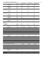
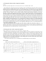
Manual for Installation and Maintenance of Condensing Boilers Therm 28 KD, KDZ, KDC INDEX: INDEX:.........................................................................................................................................................................2 1. USAGE....................................................................................................................................................................3 2. GENERAL DESCRIPTION OF THERM 28 KD BOILERS .................................................................................3 3. TECHNICAL SPECIFICATIONS..........................................................................................................................5 4. PRODUCTION CHECK .....................................................................................................................................6 5. INSTRUCTIONS FOR INSTALLATION..........................................................................................................6 ♦ POSITION OF THE BOILER.........................................................................................................................6 ♦ BOILER HANGING .......................................................................................................................................6 ♦ BOILER CONNECTION TO WARM WATER SYSTEM............................................................................6 ♦ CONDENSED FLUID DRAIN.......................................................................................................................7 ♦ BOILER CONNECTION TO DOMESTIC HOT WATER SYSTEM (DHW)..............................................7 ♦ BOILER CONNECTION TO GAS ................................................................................................................7 ♦ BOILER CONNECTION TO SUPPLY MAINS............................................................................................7 ♦ FLUE EXHAUST............................................................................................................................................8 ♦ HEATING SYSTEM FILLING ......................................................................................................................8 ♦ CHOICE OF REGULATION AND CONTROL ELEMENTS ......................................................................8 ♦ STARTING THE BOILER .............................................................................................................................9 ♦ DISCONNECTING THE BOILER.................................................................................................................9 6. INSTRUCTIONS FOR OPERATION AND MAINTENANCE ............................................................................9 ♦ OPERATING THE BOILER ..........................................................................................................................9 7. DIMS03-TH01 MODULATION ELECTRONICS...............................................................................................11 8. SIT 848 SIGMA GAS FITTING............................................................................................................................14 9. GUARANTEE AND LIABILITY FOR DEFECTS ..............................................................................................15 10. GRAPHS OF THE USABLE CONNECTING EXCESS PRESSURE OF THE HEATING WATER ...............16 11.WIRING CONNECT. OF THE THERM 28 KD BOILERS WITH THE DIMS03-TH01 AUTOMATICS........17 12.WIRING CONNECT. OF THE THERM 28 KDC BOILERS WITH THE DIMS03-TH01 AUTOMATICS.....18 13.WIRING CONNECT. OF THE THERM 28 KDZ BOILERS WITH THE DIMS03-TH01 AUTOMATICS .....19 14. THERM 28 KD SET ............................................................................................................................................20 15. THERM 28 KDZ SET ..........................................................................................................................................21 16. THERM 28 KDC SET..........................................................................................................................................22 17. HANGING THERM 28 KD, KDZ, KDC BOILERS..........................................................................................23 18. INSTALLATION VERSIONS.............................................................................................................................24 19. RECORD OF GUARANTEE / POST-GUARANTEE REPAIRS AND YEARLY MAINTENANCE CHECKS ....................................................................................................................................................................................25 2 1. USAGE Hanging condensing boilers THERM 28 KD are modern gas appliances with a forced flue exhaust (they need no chimney) suitable for heating in such houses whose heat losses do not exceed 28 kW. The combustion process taking place in these appliances is based on the principles of steam condensation. The THERM 28 KDs are boilers with maximum efficiency and minimal emissions to the air, which means that their operation is very economical and environment friendly. Their output is adjustable ranging from 18 to 100 % and it adapts itself automatically to the heating needs of the premises. The high technical standard is guaranteed by the use of top components from the world’s best producers. The engineering solutions of the THERM 28 KD boilers are the following: THERM 28 KD – modification of the boiler used only for warming of the heating appliance (the actuating circuits enabling external connection of a three-way valve necessary for the warming of the DHW supply tank have been maintained) THERM 28 KDZ – used for warming of the heating appliance and for warming of the external DHW supply tank with a continuous output modulation in both regimes THERM 28 KDC – for warming of the heating appliance and DHW through-flow heating with continuous output modulation in both regimes All boilers are provided with an expansion vessel with a capacity of 7 litres. Warning: For the proper boiler functioning, it is necessary to keep the minimum water pressure in the heating system at 0.8 bars (measured when the water is cold). If the boiler is connected to a system with an open expansion vessel, the expansion vessel must be placed at least 8 m above the boiler. 2. GENERAL DESCRIPTION OF THERM 28 KD BOILERS The THERM 28 KD gas boiler is made up of a supporting frame to which all operative elements are attached. In the upper part of the frame there is a stainless compact condensation device Giannoni that connects the combustion chamber with the burner and the two-chamber exchanger. The heat-mediating surface of the exchangers is made of circular tube plates. These must be protected against the dirt coming from the heating system which might clog them up. Therefore, it is necessary to install a filter at the return water inlet into the boiler. The collector at the outlet of the heating water is equipped with an automatic deaerating valve and a temperature indicator. The removable front wall of the device is fitted with two electrodes (ignition electrode and ionizing electrode), with a tubular burner and a modified pipiline conducting the air-gas mixture. The approriate rationing of the air-gas mixture and its mixing is ensured by a mixer and a special gas fitting. The latter contains a gas pressure regulator, two solenoid blocking valves and a ratio control of the outlet gas volume with the elements for mechaical setting. The setting of synchronous ratio control is possible only if a special instrumentation device is used. The whole system is based on the principle that the volume of the added gas is directly proportional to the volume of air supplied by the ventilator and passing through the mixer. The boiler output is consequently dependent on the volume of the air that is circulating in the system for the purposes of combustion. The running speed of the ventilator is fully controlled by means of electronic devices, which ensures a wide output range of the boiler. The air supply for the ventilator is ensured by a modified pipeline from the connecting set. The exhaust of the condensed fluid from the condensation device, as well as from the pipelines of the flue exhaust and air supply is realized through hoses conducting the condensate to a siphon trap, from where it is conducted away, outside the boiler. The adequate supply of combustion air as well as the forced flue exhaust outside the boiler is usually ensured by coaxial tubes that lead either horizontally through the perimeter wall or vertically over the roof structure out into the open space. The tubes must be installed in such a way that prevents the potential freezing of the exhaust ending (this might happen due to the low temperature of the streaming flue). For this reason it is crucial that the vertical tube be topped by a roof chimney while the horizontal tube must be installed with a moderate fall in the direction from the exhaust to the boiler. At the return water inlet there is a service pump Grundfos / Wilo that drives the water through the boiler. The sufficient flow of the heating water is ensured by a flow-switch that is a part of the multifunctional flue collector GRF 3. It is installed there together with a by-pass and a valve used for the refilling of the heating system from the DHW circuit (or, where applicable, from the external connection), and the bleed valve. The flue collector is further connected to a safety valve controlling the potential excess pressure in the boiler. The heating water outlet of the THERM 28 KDC and KDZ boilers is fitted with a motor-driven three-way valve by means of which the functions of DHW warming and warming of the heating appliance are kept apart. The process of DHW warming in the THERM 28 KDC boilers takes place within the desk exchanger. 3 The control panel is all made of plastic. On the front side there are the control elements (see the instructions for operation), in the inside there is the DIMS03-TH01 automatics containing the microprocessor controlling the boiler operations and the electric circuits participating in the ignition of the burner. Important: The type of supply of the ionizing current is determined by the neutral. It is therefore crucial that the neutral and the phase are not confused in the socket that connects the boiler to the supply mains. The installation of the socket must comply with the local valid norms. If this regulation is not followed, the boiler will not be functional. 4 3. TECHNICAL SPECIFICATIONS Nominal heat input: - natural gas - propane Minimum heat input: - natural gas - propane Nominal heat output for heating at ∆t = 80/60 °C: - natural gas - propane Nominal heat output for heating at ∆t = 50/30 °C: - natural gas - propane Nominal heat output for DHW heating: - natural gas - propane Minimum heat output at ∆t = 50/30 °C Gas screen hole: - natural gas - propane Gas excess pressure on the inlet of the appliance: - natural gas - propane Gas consumption: - natural gas - propane Max. heating system excess pressure Min. heating system excess pressure Max. DHW inlet pressure Min. DHW inlet pressure Max. heating water outlet temperature Coaxial flue exhaust diameter Average flue temperature Weight flue flow: - natural gas - propane Max. noisiness according to valid norms Boiler efficiency Boiler NOx class Nominal supply voltage / frequency Nominal electric input Nominal fuse current Level of electric components cover units THERM 28 KD THERM 28 KDZ THERM 28 KDC kW kW 26.4 23.5 26.4 23.5 26.4 23.5 kW kW 4.9 4.9 4.9 4.9 4.9 4.9 kW kW 26 23 26 23 26 23 kW kW 28 25 28 25 28 25 kW kW kW 26 23 5 5 26 23 5 mm mm 6.5 5 6.5 5 6.5 5 mbar mbar 20 37 20 37 20 37 m3.h-1 m3.h-1 bar bar bar bar o C mm o C 0.5 – 2.85 0.19 – 0.93 3 0.8 80 60/100 50 0.5 – 2.85 0.19 – 0.93 3 0.8 80 60/100 50 0.5 – 2.85 0.19 – 0.93 3 0.8 6 0.5 80 60/100 50 g.s-1 g.s-1 dB % 3.1 – 14.7 3.4 – 17 52 98 - 106 5 230 / 50 150 2 IP 41 (D) basic AA5/AB5 7 3.1 – 14.7 3.4 – 17 52 98 – 106 5 230 / 50 150 2 IP 41 (D) basic AA5/AB5 7 Volume of expansion vessel l 3.1 – 14.7 3.4 – 17 52 98 - 106 5 230 / 50 150 2 IP 41 (D) basic AA5/AB5 7 Expansion vessel filling excess pressure bar 1 1 1 DHW tank volume l - 40 – 200 - DHW temperature kept in the tank o - 65 - l.min-1 - - 12 -1 - - 11 V / Hz W A Surroundings according to valid norms DHW though-flow at ∆t = 30 oC: - natural gas - propane C l.min Boiler dimensions: height/width/depth mm 800/450/370 800/450/370 800/450/370 Boiler weight kg 45 46 47 5 4. PRODUCTION CHECK All boiler parts are rechecked and set by the manufacturer before they are assembled. Each boiler is tested for water system staunchness, gas system staunchness; regulating and safety components are rechecked and set. 5. INSTRUCTIONS FOR INSTALLATION Boiler mounting can only be done by a qualified expert company, while this has to respect all the advice and notes in this manual. The mounting has to be carried out in correspondence with valid local norms and regulations. The mounting company is required to check the suitability of the chosen boiler with respect to its functional character and customer’s requirements. Further, it is necessary to check the label on the packaging to be sure the delivered boiler corresponds with the ordered boiler and the fuel type. When it is unpackaged it is necessary to check if the delivery is correct and complete. In case of any doubts, inform the manufacturer or the supplier before mounting. ♦ POSITION OF THE BOILER The THERM 28 KD boilers may be placed both in the interior and in the non-residential areas of a house (in a boiler room, etc.). When placing the boiler inside a flat it is recommendable to set the limitation of maximum boiler output at the lower level of the power loss range and reduce thus the noise that the boiler makes when being operated at a lower output level. The boilers are equipped with IP 41 covering of electrical parts and their position in all rooms in which there is a tub or shower or which are used for bathing, must comply with the valid local norms. The room where the boiler is placed must be a “common basic environment” as it is defined in the valid regulations, which means that it has to be protected against frost with ambient temperature ranging from + 5 °C to + 35 °C with relative humidity lower than 80 %. According to the valid norms, there are certain objects that must not get closer to the boiler than: 100 mm for objects made of not easily flammable, heavily flammable and medium flammable materials. 200 mm for objects made of easily flammable materials (e.g. fibreboards, cellulose materials, polyurethane, polystyrene, polyethylene, PVC, etc.) Important: No flammable objects can be placed closer than at the safe distance from the boiler (the minimum distance of the appliance from flammable materials is 50 mm in the direction of the main heat radiation and 10 mm in the other directions). Before you start doing anything that could possibly change the environment of the installed boiler (e.g. working with paints, adhesive agents, etc.), you must switch the boiler off by the mode switch (pointer to the left). ♦ BOILER HANGING Before the boiler is mounted make sure the chosen place meets the requirements for flue exhaust placement and for minimum distances stated in the previous sections. Using the dimension scheme (see back pages in this manual) prepare the anchorage by which the boiler will be mounted. ♦ BOILER CONNECTION TO WARM WATER SYSTEM Since the THERM boiler is a warm-water through-flow boiler that is equipped with its own pump, it is possible to connect it to any existing gravity circulation system or to any new technologies designed for the forced water circulation in the heating system. With regard to the rapid temperature rise and a relatively high flexibility of the system, it is recommendable to use small volume radiators and the least dimensioned piping in the case of a new distribution system. The piping system has to be duly projected on the basis of hydraulic ratio calculations and total transmitted power. In order to use the condensation regime as effectivelly and economically as possible it is advisable to dimension the heating system for lower temperatures (∆t = 50/30 °C). If you want to achieve the maximum output of the flue exchanger and ensure a proper functioning as well as long durability of the whole system, it is necessary that the minimum excess pressure of the heating system be 0.8 bar. Before the boiler is connected to the heating system it is necessary to rinse it very carefully, so that all impurities and sediments can be removed. The heating system has to be equipped with a suitable filter and comply with the local norms.The inbuilt expansion vessel enables the boiler to be connected to a sealed heating system. The necessary expansion volume for the given system must be calculated according to the following formula: 6 Vc = V . ∆ v . 1.3 Vc V ∆v expansion volume (m3) water volume in the heating system (m3) relative increase of water volume at the increased temperature tm (if tm = 80 oC then ∆ v = 0.029) The calculated expansion volume is the smallest volume. If the calculated expansion volume is higher than the volume of the expansion vessel in the boiler it is necessary to install another expansion vessel in the system. ♦ CONDENSED FLUID DRAIN The boiler is equipped with a siphon trap that must be filled with circa 100 ml of water before the boiler is put into operation. The exhaust pipe must be installed with a falling gradient of minimum 5° from the boiler to the drainage it must not be in any way clogged (the clogging of the condensed water drain leads to resonation in the combustion chamber of the boiler). Analysis of the condensed fluid: indicator PH Nitrites Copper(Cu) Lead (Pb) Cadmium (Cd) Zinc (Zn) Unit mg.l-1 mg.l-1 mg.l-1 mg.l-1 mg.l-1 Value 3 0.01 0.2 0.01 0.004 0.12 ♦ BOILER CONNECTION TO DOMESTIC HOT WATER SYSTEM (DHW) The connection of the domestic water inlet must be done according to relevant norms and standards, with all the necessary armatures. The quality of water circulating in the DHW system is critical for the prevention of incrustation being created in the heat exchanger. Therefore it is crucial that the water meets the relevant quality norms, mainly as far as water hardness is concerned (the sum of material concentrations of calcium and magnesium < 2.5 mmol/l). If you have doubts or insecure parameters (e.g. if the users have their own well), we recommend using automatic water modification equipment. ♦ BOILER CONNECTION TO GAS The boiler must always be connected to gas by a professional company with valid certification and its professional certified employees and according to the approved documentation for gas fitting. The gas regulator is not to be fitted in front of the boiler, as it is inbuilt in the gas armature, which is a part of the boiler. A round gas cock with a certificate for gas must be fitted to the boiler’s gas inlet. The gas cock must be freely accessible. The boiler is designed for natural gas with 9 to 10.5 kWh/m3 heating power and 20 mbar nominal pressure in the distribution net and for propane with 37 mbar nominal pressure in the distribution net. Important: If you change the boiler to another gas type it is necessary to change the gas screen, too. This is situated at the screwed fitting between the gas outlet from the gas fitting and the mixer. Further, it is necessary to check, or where applicable, to reset the corresponding parameters concerning the synchronous mixing on the gas fitting. The values to be set are the amount of CO2 contained in the flue ranging from minimum to maximum boiler output depending on the flue analyser. The change and resetting can only be carried out by a trained service worker certified by the manufacturer. After the control elements are reset they have to be secured against unauthorized manipulation. The manufacturer is not liable for any damages resulting from unauthorised setting. ♦ BOILER CONNECTION TO SUPPLY MAINS The boilers are equipped with a triplex flexible cable with a plug. They are to be plugged in the socket nearby so that the plug is accessible even after the boiler is mounted. The installation of the socket must comply with the local valid norms, with the protection pin at the top and the central or neutral connected on the right from the front view. The mains voltage must be 230 V ± 10 %. The socket installation, the connection of the room thermostat, 7 and, if applicable, the connection of the outside temperature sensor THERM Q01 for weather compensated regulation, as well as the maintenance of the boiler’s electrical parts, can only be provided by a professional person qualified for electro-technical work pursuant to the valid norms. ♦ FLUE EXHAUST The boiler must be mounted with the necessary accessories (the piping for combustion air supply and flue exhaust including the outlet, distance pieces, piping armatures) that is allotted to the particular boiler type. These components are supplied separately depending on the installation type and the concrete installation conditions, and the boiler must not be put into operation without them. The possible flue exhaust installation versions are shown at the end of this manual. The basic requirements for the flue exhaust outlet of appliances with a burner with the forced combustion air supply and with the forced flue exhaust must follow relevant technical standards. The connection to a chimney, where applicable, must, too, comply with the corresponding technical standards. The actual flue exhaust solution must be designed and projected with respect to the standard regulations providing for the condensate exhaust. The horizontal piping must be installed with a falling gradient of 2° from the ending towards the boiler so that the escape of the condensed fluid from the exhaust ending into the adjacent area can be prevented. The maximum pressure loss of the flue exhaust and combustion air supply system is 80 Pa. The maximum coaxial flue exhaust lengths allowed by the manufacturer: Horizontal piping: The shortest length is 1 m, the longest is 3 m – measured from the elbow on the appliance to the outlet on the façade. Each another 90º elbow shortens the length by 0.75 m and each 45º elbow by 0.5 m. Vertical piping: The shortest length is 1 m, the longest is 2.7 m – measured from the appliance to the bottom edge of cowl collar. Each 90º elbow shortens the length by 0.75 m and each 45º elbow by 0.5 m. When a distributor and separate piping for flue exhaust and combustion air supply with diameter Ø 80 mm are used including the outlet, the stated maximum lengths can be doubled (i.e. horizontal piping can be up to 6 meters long, subtraction of the elbow resistance is still valid). ♦ HEATING SYSTEM FILLING During the time when the heating system is filled with water the boiler must be unplugged, i.e. the plug must be out of the socket. The recommended heating water pressure ranges from 1 to 1.5 bar when the system is cold. The heating system must be filled slowly so that the air bubbles can escape through the deaerating valves. The water used both for the first filling and refilling must be clear, colourless, without suspended solids, oil or chemically aggressive additives, it must not be acid (pH lower than 7), with the minimum carbonate hardness (max. 3.5 mval/l) and it must comply with the relevant local norms. If the above mentioned requirements are not met the pump, exchanger, or other components of the boiler can be damaged. The manufacturer is by no means liable either for the above mentioned damages or, where applicable, for the clogging of the exchanger, which means that the guarantee cannot be applied in such cases! To refill the heating system an inbuilt valve can be used. It can be adjusted at the bottom of the boiler (close to return water inlet). When the required pressure is reached the valve must be closed again. ♦ CHOICE OF REGULATION AND CONTROL ELEMENTS The boiler is equipped with basic regulation and safety elements, as follows from the following wiring diagrams. As further expansion, it is possible to use regulation according to the temperature in the selected reference room or the weather-compensated regulation of the heating water, or a combined regulation. The manufacturer offers a wide range of thermostats for the room temperature control, e.g. Digistat 3, Honeywell CM 27, CM 67, popř. T 8360A1000, TG - TM 100/19 and others. For the weather compensated regulation there is the outside sensor THERM Q01 offered by Thermona. A high-quality regulation can be achieved by using a smart programmable regulator SIEMENS QAA 73.110 that is continuously communicating with the boiler microprocessor via the IU02 interface. The data communication that takes place in this way concerns the required temperature of the heating system in relation to the indoor and outside temperature. It also produces information on boiler operations (nominal range of use, output, temperatures, potential defects, possible switch-off of the DHW supply tank heating at night when the scope of use is limited, etc.). The major characteristic of this system is the vast number of its adjustable and displayable parameters that ensure an ideal run of the heating system with power modulation. When you order a Therm boiler, we supply the aforementioned regulators at reduced prices. 8 Recommendation: We recommend that the operation of boilers without weather-compensated regulation be controlled at least by a basic room thermostat. The room temperature is constant and it keeps the boiler in longer operation modes. It is also recommended to set the boiler thermostat for 60 ºC in autumn and spring and for 80 ºC in winter. It is advisable to use the inbuilt weather-compensated regulation that can be also complimented by a room thermostat, as it is suggested bellow. These expansion regulation types are not delivered with the boiler. ♦ STARTING THE BOILER Only a service technician certified by the manufacturer is authorised to put the boiler in operation for the very first time. Before the boiler is ignited for the first time, it is necessary to take the following measures: Make sure that the heating system is filled with water and the boiler properly deaerated. Make sure that all the valves are open. Open the gas cock and check the tightness of the gas distribution system in the boiler. These are the steps to be taken when igniting the boiler for the first time: Set the adjusting revolving knob of the outlet temperature at the maximum. Plug the cable into the socket and start the boiler by turning the mode switch. Turn the mode switch for a short time to malfunction-unblock position, so that the boiler gets automatically ignited (this happens only if the gas inlet has been deaerated). Check whether all safety thermostats and control elements are working properly. Check the setting-up of the boiler’s output range and, if necessary, adjust the setting according to the requirements of the heated premises. Warning: The setting of boiler’s output range and other parameters must follow the manufacturer’s technical specifications. Any overloading or improper operations of the boiler can cause damage to its components! The components damaged in this way are not covered by the guarantee. ♦ DISCONNECTING THE BOILER For shorter periods, the boiler can be switched off by the mode switch or by the switch on the room thermostat. For long-term disconnection outside the heating season (e.g. during the summer holiday) it is advisable to close the gas gas cock. 6. INSTRUCTIONS FOR OPERATION AND MAINTENANCE ♦ OPERATING THE BOILER The boiler may be operated only by a person older than 18 years. Service buttons LCD display Mode switch Knob for heating temperature setting Knob for DHW temperature setting Service buttons – are used for diagnostics and setting-up of the boiler parameters 9 Manometer Setting-up of the heating temperature – revolving knob used for setting-up of the outlet water temperature in the heating system ranging from 30 – 80 oC. When operating the boiler in the mode of weather-compensated regulation, the shift of heating curve is set in the range of ± 15 °C from the curve of weather-compensated regulation. Setting-up of the DHW temperature – revolving knob used for setting-up of the required DWH temperature (35 – 60°C, only for the DHW through flow KDC boilers). Manometer – shows the pressure of water circulating in the heating system. Mode switch – has the following positions: 0 the boiler is switched off summer mode (DHW is warmed up, but the heating as such is off) winter mode (both the warming-up of DHW and the heating are on) 66 boiler’s malfunctions are unblocked service mode (also referred to as the function “chimneysweep” – set for the maximum output and maximum temperature). This mode is applicable only to service measurements that take place at the maximum boiler output (emissions, flue temperatures, etc.). LCD display: The meaning of the used symbols: - temperature, failure modes and service data in digital numbers - DHW regime (DHW temperature displayed) - heating mode (heating temperature displayed) - boiler burning - temperature - “K” factor (weather compensated mode) - summer mode selected - winter mode selected - boiler ignition failure - symbols for indication of communication with the connected interface (IU02, IU04, IU05) Indication of the set temperature: If the heating or DHW temperature regulator is turned, the corresponding mode symbol and the numerical indication of the temperature start to blink on the LCD display. In this case it is the value just being set that is indicated on the display. When the setting-up is finished, the indication of the set temperature remains there for another circa 5 seconds. The numerical data and the symbol that appear next on the display indicate the actual temperature of the given mode. Indication of malfunctions and exceeding operation values The letter “E” and the relevant malfunction code indicate concrete malfunctions on the LCD display: Malfunction code E01 E02 E03 E04 Meaning Malfunction of the boiler’s ignition Insufficient flow of heating water (between repeated tests) The sensor of the heating water is damaged 10 E05 E06 E07 E08 E09 E10 E12 The DHW sensor is damaged (relates only to KDC boilers) Malfunction concerning the exceeded limit set for the heating water temperature (blocking thermostat) The outside temperature sensor is damaged (relates to the weathercompensated regulation) Malfunction of the ventilator (feedback speed signal) Malfunction of the ventilator (the running speed outside the control range) Malfunction of the ventilator (it keeps rotating at the “stop” position) Insufficient flow of the heating water (after repeated tests) Information indicated on the display: By using the service buttons (the buttons placed at the ends; the arrow with the right hand indication “ ” – pacing forward, the arrow with the left hand indication “ ”– pacing backward) it is possible to display the boiler’s parametres in the following order: 1. 2. 3. 4. 5. 6. 7. 8. Set temperature of heating water Actual temperature of heating water Set DHW temperature* Actual DHW temperature * Outside temperature** Offset of the weather-compensation curve** Running speed of the ventilator Back to the standard indication ( + °C + the numerical value is blinking) ( + °C + the numerical value). ( + °C + the numerical value is blinking). ( + °C + the numerical value). ( + °C + the numerical value). ( + the numerical value). (without a symbol + the numerical value x 10) Once the setting has been done, the numerical value and the corresponding symbol appear on the display for 10 seconds. Then the standard mode sets in again. (*) – The KD and KDZ boilers do not display the numerical values (on the display appears “- -“) (**) – These parameters are displayed only when the weather-compensated regulation of the heating has been used (the parameter switch is in the corresponding position, the outside temperature sensor is connected and undamaged). If you operate the boiler by the CX51MC room regulator with the IU02 interface the on-going Open-Therm communication is signalled in the corners of the display by upwards pointed arrows: “ ”, in the case of cascade communication (IU04 and IU05) the arrows point downwards: “ ”. 7. DIMS03-TH01 MODULATION ELECTRONICS Dip switch – sets the type of the boiler and its parameters OFF ON DS1-DHW Supply tank Through-flow DS2-ext. sensor Without ext. sensor With ext. sensor DS3-cascade slave master DS4 DS5 DS6 Factory setting: DS1 – according to the type of boiler; DS2 – OFF (mode 1.1), DS3 – OFF; pump running-out – 50% = 5 min; anticycling delay - 50% = 5 min. Operation description: 11 1.1 Heating mode without weather-compensated regulation Setting: The sensor of outside temperature is not connected, the service switch DS2, DS3 – OFF The operating state of the boiler starts by the switching of the room thermostat (the mode switch in the winter position). In the case of KDC boilers the relay of the three-way valve is activated and the valve is reset into the heating position (the starting position of the valve is that of DHW heating, for reasons of time saving). While the valve is being reset (circa 8 sec), any efforts to ignite the boiler are blocked. In the case of KD and KDZ boilers the starting position of the three-way valve is into the heating, which means that the above mentioned cycle does not take place. Then the ventilator is put into operation and the circulation pump and ignition automatics get activated. The boiler is ignited at the output that was previously set. The set output is preserved for 2 sec from the ignition of the boiler because of the feedback from the ignition automatics. After that the output gets at the minimum level with a slow linear rise (circa 1 min) to the point of modulation that is given by the service setting of the maximum heating output. The output regulation of the boiler in this phase is categorized as the PID type (referring to its proportion/integration/derivation characteristics) while the temperature set by the revolving knob on the control panel is maintained in the range of 30 – 80 oC. If a system with an input lower than the minimum output of the boiler is heated up, the outlet temperature of the heating water exceeds the set value by 5oC. At this moment the burning in the boiler is stopped, while the circulation pump is still in operation, and the time limit of the repeated ignition is put into operation (the service setting of the time limit ranges from 0 to 10 min). Given the vast number of consequently regulated heating systems (e.g. zone regulations, thermostatic valves, etc.), the boiler functions as an exceedingly adaptable heat source. When the room thermostat opens, the pump runs down within a settable time (the factory setting is 0 – 10 minutes). This function is used to divert the heat from the condensation device and to balance the temperatures of different heating elements (useful mainly for horizontal distribution systems) if room thermostats with PI link with short operating cycles (e.g. Honeywell CM 27, CM 67) are involved. 1.2 Heating mode with weather compensated regulation Setting: Outside sensor connected, service buttons DS2 – ON, DS3 – OFF The boiler operates on the same basis as above. The only difference is that the temperature of the heating system is controlled automatically, depending on the outside temperature which is detected by the outside sensor. The calculation of the necessary temperature of the heating system is a function of the outside temperature and the „K“ factor (slope of the weather compensation curve). The factor is set by the service technician according to the natural environment of the premises and the type of the heating system. Use the adjusting revolving knob on the control panel to set the required temperature of the heating system (correction of the offset of the weathercompensation curve is in the range of ± 15 °C). The weather compensation curve is calculated for the standard heating system with radiators. Curve graphs Slopes of the weather-compensation curve Off-sets of the weather-compensation curve 12 From what can be seen above it is clear that by means of the adjusting revolving knob that is used for setting-up of the heating temperature on the control panel we can set the temperature of the heated environment at the required level. The recommended value of the starting service setting is “K” = 1.6. The user setting of the revolving regulator of the heating temperature is recommended in the medium position (the pointer pointing upwards, i.e. the off-set of the curve equals to 0 °C). When you have checked the temperature of the heated environment (such a check should take place after circa 24 hours), you can set the system according to your own requirements. By the agency of the weather-compensated regulation the changes of the outside temperature will be always compensated and the temperature of the heated environment will be automatically preserved at a constant level. By using this system of regulation we will achieve further decrease of operating costs while the heating comfort will be undeniably improved (the heating elements are heated continuously). Last but not least, we will appreciate this possibility as a pre-regulation of the primary heating circuit when using the zone regulation, mixing valves, etc. It is, of course, possible to reduce the temperature of the heated environment by connecting a room thermostat to the system. In this case we recommend the type without the PI regulation which is equipped only with a switching mechanism working on the basis of temperature gaps. We set the temperature by the revolving regulator at a level that is slightly higher than it would be for the operation without the room thermostat. Should the sensor of outside temperature be working improperly, the malfunction will be immediately signalled and the boiler will resume operation at the temperature level that was set in the previous mode (1.1 – heating mode without weather-compensated regulation). 2. DHW through-flow heating mode (28KDC) Setting: Service switch DS1 – ON, DS2 as mentioned above, DS3 – OFF. The operation phase of this mode begins by switching the DHW through-flow switch. The ventilator is put into operation and the circulation pump and ignition automatics get activated. The mode ignites the boiler at the starting power (circa 10 sec after the boiler’s ignition) and increases the boiler output at the maximum level so that the outlet temperature that was previously set by the user can be achieved as soon as possible. This temperature is later maintained by the output regulation of the PID type. If two requirements should appear simultaneously, the heat-up of the DHW takes precedence over the heating. 3. Heating mode of the DHW supply tank (28KDZ) Setting: Service switch DS1 – OFF, DS2 as mentioned above, DS3 – OFF. The operation phase of this mode is started by switching of the supply tank thermostat. The three-way valve’s relay is activated and reset into the heating position. The relay of the pump and ignition automatics are activated after circa 8 sec. The mode ignites the boiler at the starting power (2 sec after the boiler’s ignition) and increases the boiler output at the maximum level so that the outlet temperature 80 oC can be achieved as soon as possible. This temperature is later maintained by output regulation of the PID type. Once the supply tank is heated, the thermostat is disconnected and the heating in the boiler is stopped. After 10 sec the pump halts and stops the threeway valve relay which sets it into the heating position. While the valve is being reset (circa 8 sec), any efforts to ignite the boiler are blocked. When the re-setting is finished the boiler can resume heating of the system according to the user’s requirements. If two requirements should appear simultaneously, the heating-up of the DHW supply tank takes precedence over the heating. Additional functions: ∗ When the heating in the boiler stops, the ventilator keeps on working for 20 more seconds at the initial running speed (the remaining flue is removed from the combustion chamber). ∗ The pump is regularly put into operation if the boiler is out of action (it is working for 30 sec if no operation took place during the last 24 hours). ∗ The three-way valve is regularly switched (for 10 sec if no operation took place during the last 24 hours). ∗ The anti-frost protection is activated whenever the temperature in the boiler gets bellow 6 oC. The three-way valve is reset into the heating position (depending on the type of the particular boiler), the pump is put into operation; the boiler is ignited and starts to heat the heating circuit up to 30 oC. Once this temperature is regained, the anti-frost protection is automatically switched off. 13 ∗ A repeated check of the through-flow switch is activated whenever it does not switch within 15 sec after the pump started to operate. The pump halts and when another 45 passes, another attempt to start the boiler is made. This is repeated ten times. If the tenth try is not succesfuls, it is necessary to switch the boiler off and switch it on subsequently by the mode switch. If the non-operation state of the pump between the halt and the repeated start of the boiler lasts longer than 30 min, the first operation interval of the pump is prolonged at 180 sec. The intervals between the individual test cycles are indicated according to the following list of malfunctions. An accredited service technician is bound to inform the user about the correct use of the boiler, about its parts and safety elements, to fill in the letter of guaranty and to give the user this manual. The user has to use the boiler only in the ways described in this manual. This is also the condition for guarantee. The user is strictly forbidden to change or interfere with the fixed parts of the boiler! 8. SIT 848 SIGMA GAS FITTING setting of the starting point of regulation solenoid coils air pressure signal inlet setting of the air/gas ratio module for measuring the inlet gas pressure module for measuring the outlet gas pressure gas outlet gas inlet SIT 848 SIGMA is a gas fitting with proportional regulation: air/gas. It is equipped with two solenoid valves that prevent the penetration of gas at the time when the boiler is out of operation. The regulation system works in correlation with the feedback signal of the gas pressure from the mixer. Apart from the lockable measuring modules of the inlet, outlet and medial gas pressure, there are devices that make it possible to set the correct air-gas ratio throughout the output regulation range. 1. Starting point of the regulation – setting: The setting is done by means of a screw that is placed at the pad of the regulation system of the auxiliary membrane. The screw is only accessible if a brass cover is removed. The air-gas ratio is set at the minimum output of the boiler (i.e. at the minimum running speed of the ventilator.) If the screw is screwed in, the proportion of gas in the mixture gets lower. 2. The air/gas ratio – setting: The setting is done by the regulation screw of the gas throttle placed at the gas valve outlet. The air-gas ratio is set at the maximum output of the boiler (i.e. at the maximum running speed of the ventilator). If the screw is screwed in, the proportion of gas in the mixture gets lower. The solenoid coil connector - wiring diagram: 14 The gas fitting contains two solenoid valves: EV1 (gas inlet solenoid) and EV2 (regulation system solenoid). The connecting cable’s coils are arranged in parallel (i.e. they are activated simultaneously). The supply voltage of the coils is 220 VAC. 9. GUARANTEE AND LIABILITY FOR DEFECTS The manufacturer is not to be held liable for any mechanical damage of individual components caused by malpractice, for defects caused by unprofessional handling with the electronics while adjusting or adding extension regulations, or for defects caused by using other parts and components than the original ones used by the manufacturer. Further, the guarantee does not cover any defects caused by disregarding important notes and conditions stated in individual paragraphs of this manual for operation and maintenance. The guarantee covers neither situations caused by non-standard conditions in the distribution network (voltage fluctuation and overvoltage peaks, gas pressure and purity etc.), nor defects of appliances outside the boiler, which influence its function, inadequate flue exhaust, impurities in the combusted air, damage caused by external agency, mechanical damage, storing, transport, nor defects caused by natural disasters. In these cases the service company may also require that the customer pay for the repairs. THERMONA spol. s r. o. provides a 24 months guarantee that is due to start at the time when the boiler is put into operation for the first time. Conditions for guarantee application: 1. The maintenance check of the boiler must be carried out regularly once a year. It may be done only by an authorized company bound by a relevant contract. 2. Records of all guarantee repairs and yearly maintenance checks must be kept on the sheet attached in the appendix of this manual. 15 10. GRAPHS OF THE USABLE CONNECTING EXCESS PRESSURE OF THE HEATING WATER Connecting excess pressure for THERM 28 KD 500,0 Outlet excess pressure (mbar) 450,0 400,0 350,0 300,0 Wilo 3 250,0 Grunfos 3 200,0 150,0 100,0 50,0 0,0 0,4 0,6 0,8 1 1,2 3 Water through flow (m / h) Connecting excess pressure for THERM 28 KDC, KDZ 500,0 Outlet excess pressure (mbar) 450,0 400,0 350,0 300,0 Wilo 3 250,0 Grunfos 3 200,0 150,0 100,0 50,0 0,0 0,4 0,6 0,8 1 1,2 3 Water through flow (m / h) Warning: The curves of the applicable connecting excess pressure of the heating water have been produced to match the Wilo 25/70 and Grundfos 15/60 pumps when these are set for the highest regulation degree. Given the speed at which the supply tank of the THERM 28 KDZ boilers is heated, it is not recommended to reduce the pump output any further. 16 11.Wiring connect. of the THERM 28 KD boilers with the DIMS03-TH01 automatics 17 12.Wiring connect. of the THERM 28 KDC boilers with the DIMS03-TH01 automatics 18 13.Wiring connect. of the THERM 28 KDZ boilers with the DIMS03-TH01 automatics 19 14. THERM 28 KD SET 450 Deaerating valve WATTS store no. 40430 Heating temperature sensor store no. 21045 Giannoni condensation device store no. 23821 Ignition electrode store no. 23640 Ventilator MVL 130/24 store no. 22141 Ionizing electrode store no.20342 Mixer SIT store no. 40390 Gas valve SIT store no. 40848 Expansion vessel 7l store no. 22168 Seal-pipe store no. 23405 Blocking thermostat store no. 40035 Transformer 220V/24V store no. 482417 Grundfos pump store no. 40013 Safety valve store no. 20791 GRF 3 through-flow switch store no. 22159 Control panel store no. 41368.1 Heating water outlet G 3/4" Gas inlet G 1/2" Condensate outlet Safety valve outlet G 1/2" Heating water inlet G 3/4" 70 86 20 15. THERM 28 KDZ SET 450 Deaerating valve WATTS store no. 40430 Heating temperature sensor store no. 21045 Giannoni condensation device store no. 23821 Ignition electrode store no. 23640 Ventilator MVL 130/24 store no. 22141 Ionising electrode store no. 20342 Mixer SIT store no. 40390 Gas valve SIT store no. 40848 800 Expansion vessel 7l store no. 22168 Seal-pipe store no. 23405 Blocking thermostat store no. 40035 Transformer 220V/24V store no. 482417 Three-way valve store no. 21053 Grundfos pump store no. 40013 Safety valve store no. 20791 GRF 3 through-flow switch store no. 22159 Control panel store no. 41368.1 38 35 79 Condensate outlet Safety valve Gas inlet Heating water outlet G 1/2" outlet G 3/4" DHW inlet G 1/2" Heating water DHW outlet inlet G 3/4" G 3/4" G 3/4" 70 55 60 89 52 38 21 86 16. THERM 28 KDC SET 450 Deaerating valve WATTS store no. 40430 Heating temperature sensor store no. 21045 Giannoni condensation device store no. 23821 Ignition electrode store no. 23640 Ventilator MVL 130/24 store no. 22141 Ionizing electrode strore no. 20342 Mixer SIT store no. 40390 Gas valve SIT store no. 40848 Expansion vessel 7l store no. 22168 Seal-pipe store no. 23405 Blocking thermostat store no. 40035 Transformer 220V/24V store no. 482417 Three-way valve store no. 21053 DHW exchanger store no. 21988 DHW temperature sensor store no. 21045 Grundfos pump store no. 40013 DHW through-flow switch store no. 20166 GRF 3 through-flow switch store no. 22159 Safety valve store no. 20791 DHW inlet G 1/2" DHW outlet G 1/2" Gas inlet G 1/2" Heating water outlet. Safety G 3/4" valve outlet G 1/2" 50 Heating water inlet Condesate outlet G 3/4" 86 22 Control panel store no. 41368.1 I 17. HANGING THERM 28 KD, KDZ, KDC BOILERS 23 18. INSTALLATION VERSIONS Realizations: C13 – Coaxial horizontal version with the outlet into the perimeter wall. The piping can also be doubled, the outlets are either concentric or placed so closely to each other (not further than 50 cm) that they are exposed to the same climatic conditions. C33 – Coaxial vertical version with the outlet onto the roof. The piping can also be doubled, the outlets are either concentric or placed so closely to each other (not further than 50 cm) that they are exposed to the same climatic conditions. C43 – Separated connection to two pipelines within the same shaft. The outlet of both shafts is either concentric or placed so closely to each other (not further than 50 cm) that they are exposed to the same climatic conditions. C53 – Separated pipelines with the outlet into the perimeter wall or onto the roof, into two zones of different pressure, but never into two opposed perimeter walls. C83 – Separated connection with the flue exhaust into a separate or common chimney. The supply of combustion air is provided through the perimeter wall. 24 19. RECORD OF GUARANTEE / POST-GUARANTEE REPAIRS AND YEARLY MAINTENANCE CHECKS Operation Authorized company Customer’s signature Date Warning related to the disposal of package and product after the serviceable time All material used for production correspond with the requirements of valid norms and regulations. The product packaging should be taken to the paper disposal area, while the package film should be disposed in the public containers in which the plastic materials are collected. The boiler parts made of steel, copper and copper alloy is to be disposed of separately in the metal disposal area. Heat insulation of the combustion chamber is harmless to health and can be disposed of together with the domestic refuse. 25 PRODUCT QUALITY AND COMPLETENESS CERTIFICATE THERM condensing gas boiler Type: THERM 28 Serial number: This product fulfils all the relevant guidelines, technical norms and regulations and its operation is safe under common conditions. Measures have been taken to secure the accordance of this product with the technical documentation and with the basic technical, safety and hygienic requirements. This product is certified by the Engineering Testing Institute, authorized person 202: THERM 28 KD, THERM 28 KDC, THERM 28 KDZ - certificate for type testing according to the EC directives for gas appliances 90/396/EEC No. E-30-00712-02. THERM 28 KD, THERM 28 KDC, THERM 28 KDZ – certificate for efficiency according to the EC directives 92/42/EEC No. E-30-00761-02. The condensing gas boilers THERM 28 KD, THERM 28 KDC and THERM 28 KDZ are holders of the “environment-friendly product” trademark No. 11 - 20. They are numbered among the products with a minimum negative impact on the environment. Technical check Date:……………………………………………………………… Stamp and signature:……………………………………………… THERMONA, spol. s r. o. Stará osada 258, Zastávka u Brna, 664 84 Tel.+fax: 546 411 006, 546 411 230, 546 429 200 26