1
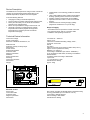
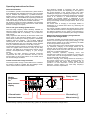
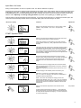
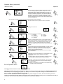
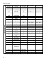
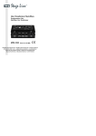
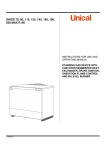
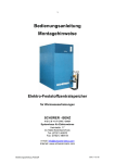
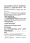
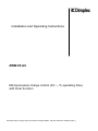
Installation and Operating Instructions ZWM 05 AC Microprocessor charge control (AC ~, % operating time) with timer function Microprocessor charge control for electric storage heaters, with AC reference variable (230V~) Table of Contents Contents Device Description Technical Device Information Operating Instructions for Users Input Menu for Users Installation and Operating Instructions for Technicians Charge Control Set-Up Control Examples Connection Diagrams Direct Control Setting the Charge Control Setting Examples Input Menu for Technicians Start-Up Start-Up Protocol Correcting Basic Settings Diagnostic Information After-Sales Service 2 Page 3 3 4 5 7 8 9 10 12 12 13 14 19 19 21 22 23 Device Description The ZWM 05 AC microprocessor charge control controls the charging of storage heating devices depending on the external temperature, adjusters and control signals. It has the following features: Charging according to external temperature, Timer function for forward, backward and spread control, Priority and secondary use of actual service release periods for low and high tariffs, Direct control possible via charge control line Z1 / Z2 Automatic correction of charging during extreme temperature fluctuations (daytime and night-time temperatures) in transition periods via external temperature averaging, Characteristic curve switching possible via external control, Large, back-lit alphanumeric multifunctional display showing operating status and service information, All utility company requirements can be fulfilled, Optional connection to NTC or older PTC external sensors, Real-time timer for lowering charging (weekly programme and absence of up to 30 days). Scope of supply - The ZWM 05 AC microprocessor central control unit - NTC external sensor with 2m connection cable - Installation and operating Instructions. Technical Device Information Connection voltage Power consumption Reference variable at terminals Z1, Z2: 1/N/ 230V AC ~ 50/60 Hz Approx. 2 VA Tone burst-controlled alternating voltage, 230V~, Cycle time 10 seconds 300 W 6A, 230V ~ Class G fuse insert F2 according to DIN 41660 (1.6A T) Approx. 6 hours (runtime and clock) Between 0 °C and 50 °C II according to installation (see section “Installation”) IP 20, according to DIN 40050, according to installation DIN EN 50350 6 modular spaces according to DIN 43880 Top hat rail 11, cross section 2.5 mm² See dimension drawing approx. 320g Maximum load Switching capacity of safety output Device fuse Power reserve Ambient temperature Protection class Degree of protection Standard Space requirements Mounting Connection terminals Dimensions Weight 105 Internal fuse R é v. 1 1.6 AT S D im plex M ODE LL ATM LF Abw LZ SUT KU D ED SUS E5 AT W E2 E4 E3 E15 E1 E10 A C - Z e n t r a ls te u e r g e r ä t 2 VA 230V 50 Hz L 1 N 2 LL LF LZ KU 3 4 5 6 6A SH 7 1,3A 230V Z2 Z1 8 9 83 ZW M 05AC E - N r.: 2 1 / 0 3 0 4 ( 0 1 ) W2 W1 10 11 10 50 mm 12 External sensor Sensor type Connection cable Protection class Degree of protection Dimensions NTC sensor according to DIN EN 50350 in insulated casing 2m long (extendable up to a maximum of 30 m) II according to DIN EN 60730-1 IP54 according to DIN 40050 See dimension drawing 3 Operating Instructions for Users This reference variable is connected, with the various settings and the runtime, and depending on the signals of the control terminals, to the central control unit’s output variable (set charge rate = operating time signal to Z1 / Z2). The charge controller that is fitted as standard in the storage heater is an electronic or thermomechanical ON/OFF controller. Its controller setpoint is determined by the pending operating time signal (on device terminals A1~/A2~) and by the intensity actuator (charge selector knob on the storage heater). The actual value of charging in all storage heaters is determined via a residual heat sensor by measuring the core temperature. The charge controller compares the setpoint with the actual value and calculates the level of charging required based on the difference between the two values. Power switching in the storage heater is thus controlled by the charge controller. General Information For installation, operation and maintenance, please observe these installation and operating instructions. This unit should only be installed and repaired by a qualified technician. Repairs which are improperly carried out can endanger the safety of the user. The installation and operating instructions must always be available and should be given to the technician working on the device for his/her information. We therefore request that these installation and operating instructions be passed on to the new tenant or owner should there be a change in occupancy. This is how your heating system works The local utility company makes electricity available for electrical heating purposes during periods in which other customers require little or no electricity – the so-called offpeak periods. Utility companies offer electricity at discounted tariffs, with priority given to the night-time release period. In certain service areas, electricity for heating purposes is additionally available during the daytime – the so-called additional release period. For release and additional release periods, the tariff requirements can vary. Information can be obtained from your authorised electrician or local utility company. The specified charging periods are generally released via a control unit (ripple control receiver or timer) by the utility company. The ZWM 05 AC microprocessor charge control ensures consumption-based charging of your storage heating. To ensure the utility company’s technical connection requirements are met, your electrician will carry out the precise setting of all required values on the central control unit and the charge controllers. Setting the intensity actuator (charge selector knob) on the storage heater In automatic operation, the intensity actuator on the storage heater is set at the right-hand stop (factory setting), i.e. the storage heater charges at the value specified by the ZWM 05 AC microprocessor charge control. In areas which always have reduced heating requirements, e.g. bedrooms, charging of the storage heater can be reduced and the storage heater adjusted, by turning the charge selector knob to the left. With the knob at the lefthand stop, no charging takes place. During automatic operation, operating errors and unintentional re-setting can be prevented by removing the control button from the storage heater’s intensity actuator and covering it with the closing cap. Should no charging of the storage heater be necessary in the summer months (even on cooler summer nights), we recommend taking the entire heating system out of operation. For more information, consult your authorised electrician. Please observe your local utility company’s technical connection requirements. Central control and charge controller The microprocessor charge control ZWM 05 AC measures the weather conditions, together with the building’s inertia, via the external sensor located in the brickwork. Weekly Wochenproprogramme gramm Ein On Multi-function Multifunktionsdisplay display D im plex MODE LL AT M LF Abw LZ SUT KU D ED SUS Rotary switch Drehwahlschalter E5 AT W LED E2 E4 E3 E15 E1 E10 A C - Z e n t r a ls te u e rg e r ä t ZW M 05AC E -N r.: 2 1 / 0 3 0 4 (0 1 ) Forward button Taster Vorwärts Plus button Taster Plus[+] [+] Backward button Taster Rückwärts Minus Tasterbutton Minus [-] [-] The heat storage capacity of the entire heating system can be raised or lowered on the charge control. 4 Input Menu for Users During normal operation, the unit is in operator mode. The “Mode” LED does not light up. The menu item shown in the display therefore depends on the position of the rotary selector switch as well as the setting of the ANZ (display) menu item. In operator mode, the individual menu items of the operator menu can be accessed with either the FORWARDS [▼] button or the BACKWARDS button [▲]. Individual menu items can also be directly accessed via the rotary selector switch. Adjusting the flashing setting parameters is possible via the "plus" [+] or "minus" [-] buttons. Changes will be made automatically with this adjustment. If 3 minutes should elapse and no adjustment has taken place, the control device automatically switches back to the selected display status and the changes are saved. Menu item / display Comment Adjustment Display of the week day and the time in “Timer function” mode (TIMER = YES) and DIS = Timer / DIS = AS (automatic switching). START Operator Menu Runtime LA Display of the time that has elapsed since the start of the nighttime charge release (start of charge release/LF) (Note: When release synchronisation is active (FSU (release synchronisation with timer) = YES), adjustment of the runtime is blocked). Charge level E5 Changes to the basic charge level of all storage heating systems connected to the charge control. The set charge can be either proportionally raised or lowered by up to 30%, according to need. The change to the charge level should only be made gradually, since the effect of these changes will only become apparent after the unit has been charged. Charge start E2 Specifies the effective external temperature (ATW) at which storage cylinder charging should begin. (The higher the selected setting, the earlier charging will start and the higher the set charge amount at the same effective external temperature / ATW). Base charge start E15 Specifies the minimum charging base which comes into effect when the effective external temperature set via E2 is undershot. Recommended setting: Insufficient charging in the transition period: raise E15 by 5% to 10%. Excess charging in the transition period: lower E15 by 5%. Additional charging (daytime charging) E10 Reduction or increase of an available daytime charging E10 = 0% means no charging in the afternoon, independent of the effective external temperature. Notes: In the event that the daytime charging via the TAS (daytime skip) adjuster (TAS = E1 or TAS = TE; only accessible to technicians) is generally disabled at higher effective external temperatures, then the E10 adjuster is ineffective above these temperatures. Effective external temperature (ATW) Display of the effective temperature at the external sensor location Not possible (at ATM (external temperature averaging) = 1: ATW (effective external temperature) corresponds to the averaged temperature at ATM (external temperature averaging) = 0: ATW corresponds to current temperature) 5 Operator Menu (continued) Menu item / display Comment Adjustment Real-time timer The microprocessor charge control is equipped with a real-time function / weekly programme (TIMER = YES). This can be utilised either strictly as additional information or for automatic charge lowering during longer periods of absence and/or according to the weekly programme. This offers the additional possibility, in connection with the FSU (release synchronisation with timer) = YES function, to release or individually conceal charging independent of the time in areas without release signal in a time-controlled way. Note: This can no longer be switched off after the real-time timer has been activated! Extended runtime function (real-time function) is activated Setting the time Setting the current time Weekday Setting the current day of the week: T1 = Monday T5 = Friday T2 = Tuesday T6 = Saturday T3 = Wednesday T7 = Sunday T4 = Thursday Display Selection of desired display mode in normal operation DIS = AS (switch position indicator): according to the position of the rotary selector switch DIS = Timer: displays the time and day of the week DIS = AU (switch position indicator, timer): automatic switching of display between rotary selector switch position and time/day Days of absence For the duration of the days selected (between 1 and 30), the KU (heating curve switching) is activated according to the KUT (heating curve switching, temperature) or KUP (heating curve switching, percent) setting parameters. After the period of absence has elapsed, the normal charging curve is reactivated. Weekly programme Depending on cyclic user preferences, a mode between normal and lowered charging can be selected via the weekly programme. The active weekly programme is denoted in the display by the “Wochenprogram” (weekly programme) symbol (WeP). Weekday When WeP = YES, each day of the week (Mo – Su) can be set to the appropriate heating curve (normal or lowered charging). Nor: normal charging KU (heating curve switching): from 8:00 pm of the previous day lowered charging (KU) activated. End of Operator Menu Changing to the technicians’ menu in the display mode. When the FORWARD button [▼] is held down for approx. 10 seconds, the device will switch to the display mode (menu for technicians). The LED display (green) lights up in display mode, and the configuration settings can be accessed via the "" and "" buttons. Changing the settings is not possible. Should no button be pushed in the active display mode for a period of approx. 3 minutes, the unit automatically returns to operator mode after this time has elapsed. The display mode can also be ended by holding down the FORWARD button [▼] for 10 seconds. The menu item selected via the rotary selector switch will be displayed. . 6 Installation and Operating Instructions for Technicians Installing the central control unit Installing the external sensor Installation must only be carried out by a technician authorised by the respective utility company. The regulations of the local utility company, as well as the relevant electrical standards regulations are to be observed. The unit requires 6 DIN 43880 modular spaces. Protection against accidental contact according to protection class II is ensured by: The NTC external sensor is to be installed at least 2m above the floor, preferably in the outer brickwork of the zone of main use (with large systems) or in the room of main use (with single systems). The sensor should not be exposed to direct sunlight. Heat sources (e.g. ventilation shafts or tilted windows) must not influence the sensor and thus affect the ZWM 05 AC microprocessor charge control. Please observe the following: Small installation distribution board according to DIN 57603/VDE 0603 (e.g. N system distribution board) The external sensor must be embedded in the mortar The cable feedthrough must be carefully protected with thermal insulation material. The NTC external sensor has a 2m long connection cable, which can be extended to a maximum of 30m using an installation lead (1.5 mm² minimum). Installation distribution board according to DIN 57659/VDE 0659. The charge control unit should be installed in the coolest location, i.e. the lowest mounting row of the distribution board. Please ensure a distance the length of one modular space on both sides. The unit comes complete with lead-sealable cover caps, which are to be used for installation in the installation distribution board only. These must be removed before installation. Wall with outside isolation außen Outside Wall with or without inside insulation außen innen Inside Outside Mauerwerk Brickwor Mauerwerk Brickwor Beton Concret Außenfühler External max. 1cm Max. 1 Außenfühler External max. 1cm Max. 1 Putz Plaste Wärmedämmung Thermal Putz Plaste Wärmedämmung Thermal Wall with curtain-type façade außen Outside Beton, Eternit Concrete, oder Fassadenstein cement or facing LuftAir innen Inside Pre-fabricated house wall außen Outside innen Inside innen Inside Wandelement Wall section (außen) Wandelement Wall section (innen) Außenfühler External max. Max. 1 1cm Außenfühler External Wärmedämmung Thermal Beton Concret Wärmedämmung Thermal Electrical Connection The circuitry stipulated by the local utility company may vary from these connection examples. The appropriate circuitry is normally listed in the utility company’s technical connection requirements. The LF (charge release), LL (runtime) and LZ (additional charging) terminals are to be wired in compliance with the utility company’s requirements via floating contacts, e.g. a ripple control receiver or a tariff timer. When connecting the ZWM 05 AC microprocessor charge control, please observe the following: The connections at terminals L and N should not be interchanged The LL (runtime), LF (charge release), LZ (additional charging) and KU (heating curve switching) pilot wires must be connected in phase with L (charging) Should a phase be connected to terminal W1, W2, Z1 or Z2 due to a mistake in the wiring, the unit will be destroyed. Control lines must consist of two-core wires according to DIN 44573. According to the relevant standards, these two-core wires must not be laid in the same cable as network wires. 7 Device type Control output per device VFM 10 Watts VNM 14 Watts VKM, ESK 9 Watts VFMi, ESS, ESF, ESN, EST 9 Watts VFDi, VFD 0.5 Watts VNDi, VTDi 0.5 Watts VKD 0.5 Watts FSD 0.5 Watts Calculating the Control Output The maximum control output of the ZWM 05 AC charge control is 300 W. The control output of the heating system depends on the device type and number of devices. It can be calculated by adding the control outputs of all storage heaters. The following table shows the control outputs of selected storage heater types. ZWM 05 AC charge control set-up ButtonSondereinstellungen for special settings Taster Gerätesicherung Internal fuse R é v. 1 1.6 AT S D im plex Multi function display Multifunktionsdisplay Taster M ODE LL AT M LF Abw LZ SUT KU D ED SU S E5 AT W E2 E4 E3 E15 Buttons E1 E10 A C - Z e n t r a ls te u e rg e r ä t 2 VA 230V L 1 50 Hz N 2 LL LF LZ KU 3 4 5 6 6A SH 7 Rotary Drehwahlschalter switch 1,3A 230V Z2 Z1 8 9 ZW M 05AC E - N r. : 2 1 / 0 3 0 4 ( 0 1 ) W2 W1 10 11 Terminals W1, W2 Klemmen W1/W2 Außenfühler External sensor Klemmen L, N Netz Terminal L, N - Power supply Klemme LL Terminal Start desLL Zeitgliedes -Timer start Klemmen Terminals Z1, Z2Z1, - Z2 Control ED-Steuersignal signal output LF - Release period KlemmeTerminal LF Freigabedauer Terminal release period KlemmeLZ LZ- Additional Zusatzfreigabedauer Terminal curve switching Klemme KU KU - Heating Kennlinienumschaltung Terminal Klemme SH SH Relaisausgang Ladeschütz Relay output for charge contactor Explanation of multi-function display items LL: LF: Activated when LL terminal is activated Activated when LF (charge release) terminal is activated LZ: Activated when LZ (runtime) terminal is activated KU: Activated when KU (heating curve switching) terminal is activated ED: Activated when the control signal is output ATM: Activated in external temperature averaging operation (ATM (external temperature averaging) = YES) Abw: Activated in period of absence (Abw) mode SUT: Activated when the control signal is suppressed in the daytime characteristic curve D: Activated in direct activation mode SUS: Activated when the control signal is suppressed and the effective external temperature (ATW) is higher than the value set for E2 : Weekly programme display “WeP=Yes” : “LSU (charge synchronisation with timer) = YES LED operating mode display: If display is not lit – operator mode is active Green light – technician menu display mode is active Red light – technician menu setting mode is active Orange light (brief) – software has been reset . 8 Activation Examples for ZWM 05 AC Microprocessor Charge Control Backward or spread control with timer function Standard installation with heating contactor or direct activation (via charge control) without heating contactor Release signal (LF) at terminals LL and LF Voltage at “LF” (charge release) terminal: Output of the weather-dependent and runtime-dependent operating time control signal Timer element activated (timer is running) R é v. 1 1 .6 AT S D im p lex MODE LL AT M LF Abw LZ SUT KU D ED SUS E5 AT W E2 E4 E3 E15 E1 E10 ZW M 05AC A C - Z e n t r a ls te u e r g e r ä t L N LL LF LZ KUSH Z2 Z1 1 2 3 4 5 6 7 8 E - N r. : 2 1 / 0 3 0 4 ( 0 1 ) W2 W1 9 10 11 No voltage at “LF” (charge release) terminal: Runtime (LA) < locking duration (SEH): Timer element deactivated (timer is stopped). Runtime (LA) > locking duration (SEH): Timer element activated (timer is running). Output of the weather-dependent and runtime-dependent operating time control signal. When direct activation mode is activated: Safety overlap to 100% operating time (= charge suppression) *For charge types with daytime charging periods and special LZ (additional charging) release signals, the “LZ” terminal must be activated (Please observe the technical connection requirements of the utility company). Forward control without timer function Standard installation with heating contactor R é v. 1 1.6 A T S D im plex M ODE LL AT M LF Abw LZ SUT KU D ED SUS E5 AT W E2 E4 E3 E15 E1 E10 ZW M 05AC A C - Z e n t r a l s te u e r g e r ä t L N LL LF LZ KUSH Z2 Z1 1 2 3 4 5 6 Remove LL-LF bridge and insert bridges between L-LF and LF-LZ Output of the weather-dependent operating time control signal Timer element is not activated (timer is stopped) Runtime display = LA (runtime) 0.00 hours 7 8 9 E - N r.: 2 1 / 0 3 0 4 ( 0 1 ) W2 W1 10 11 Forward or spread control with timer function Standard installation with heating contactor or direct activation (via charge control) without heating contactor Lay LF (charge release) or SH (heating contactor activation terminal) release signal from utility company to LF terminal and bridge between LF and LZ R é v. 1 1.6 A T S D im plex M ODE LL AT M LF Abw LZ SUT KU D ED SUS E5 AT W E2 E4 E3 E15 E1 E10 A C - Z e n t r a l s te u e r g e r ä t L N LL LF LZ KUSH Z2 Z1 1 2 3 4 5 6 7 8 9 ZW M 05AC E - N r.: 2 1 / 0 3 0 4 ( 0 1 ) W2 W1 10 11 Voltage to “LF” terminal Output of the weather-dependent operating time control signal Timer element activated (timer is running) No voltage at “LF” (charge release) terminal: Runtime (LA) < locking duration (SEH): Timer element deactivated (timer is stopped). Runtime (LA) > locking duration (SEH): Timer element activated (timer is running). When direct activation mode is activated: Safety overlap to 100% operating time (= charge suppression) 9 ZWM 05 AC connection diagram for electric storage heaters Charge control unit ZWM 05 AC Group control unit GRM 05 AC (Option) Storage heater External sensor * Terminals depend on storage heater type Contact for heating curve lowering (optional) To additional storage heaters Without group control unit: To storage heater terminal A1~, A2~ Room thermostat Low tariff power supply Auxiliary relay Example A: Release contact LF Tariff timer or ripple control receiver 10 Heating contactor Example B: Release contact LF, LZ ZWM 05 AC connection diagram – external temperature-dependent and runtime-dependent control via SH control output Charge control unit ZWM 05 AC External sensor The SH terminal can be used to activate a heating contactor for storage heaters without a control signal input or storage heaters from alternative manufacturers dependent on weather conditions. Requirements are as follows: Set the central control unit to backwards control (E3) Activate the central control unit by release contact LF The SH output (L potential) also depends on: - The external temperature, - the preset running time (LA) - a preset charge rate higher than 0%. To storage heater Contact for heating curve lowering (optional) Tariff timer or ripple control receiver Release contact LF Auxiliary relay Heating contactor Low tariff power supply 11 Direct activation via charge control line Z1/Z2 The ZWM 05 AC microprocessor charge control can be used for direct activation of VFDi, VFD, FSD, VNDi, VTDi and VKD storage heaters with electronic charge control via the charge control line. For direct activation via the Z1/Z2 charge control line, the network connection does not lead through the heating contactor but rather directly to the connection terminals of the storage heater. A constant voltage is connected to terminals L1, L2 and L3. Activation for charge release is switched by the utility company via the central control unit. At terminals Z1/Z2, the weather-dependent and runtime-dependent control voltage is only active when “LF” or “LZ” terminals are controlled. When terminal “LF" or “LZ” is not activated, the central control unit provides 100% operating time signal (constant voltage), thus blocking the charging of the storage heater. For direct activation, the “Digital system” adjuster must be programmed to “D = YES”. Setting the Charge Control The charge control must only be set by an experienced technician. The ZWM 05 AC microprocessor charge control is preset as a backward control for an 8-hour lower tariff-only release period. If adjustments to the technician menu are necessary, configuration mode must be activated by pushing the “Special settings” button. E1 Charge curve Set heating content in % Effective external temperature 12 E3 Night time curve E10, E4 Day time curve Setting Examples Charge type Duration of release period tF Duration of additional release period tZF Between 9 p.m. and 7 a.m. - 8+0h Between 9 p.m. Between 1 p.m. and 4 p.m. and 7 a.m. 8+2h 2h Secondary 8+4h 8h Spread Between 9 p.m. and 7 a.m. 4h Secondary Between 12 p.m. and 9 p.m. 8+7h 8h Backward 7h Secondary Between 9 p.m. and 7 a.m. - 9+0h Between 9 p.m. Between 1 p.m. and 4 p.m. and 7 a.m. 9+2h 2h Secondary Between 8 p.m. and 6 a.m. - 10 + 0 h 10 h Backward Between 8 p.m. and 6 a.m. Between 12 p.m. and 6 p.m. 10 + 6 h 10 h Backward E.g. E.g. - 14° C + 15° C 15% Effective - 10° C - 12° C - 14° C - 16° C - 18° C 100 % - 4° C - 6° C - 7° C - 9° C - 10° C - 10° C - 12° C - 14° C - 16° C - 18° C 7h 100 % 0° C - 1° C - 3° C - 4° C - 5° C - 10° C - 12° C - 14° C - 16° C - 18° C 4h 30 % + 4° C - 10° C + 3° C + 3° C + 1° C 0° C - 12° C - 14° C - 16° C - 18° C 7h 30 % ** 8h Effective - 10° C - 12° C - 14° C - 16° C - 18° C 8h 25 % ** 9h Effective 9h 30 % E.g. + 15° C E.g. 15% E.g. + 15° C E.g. 15% 100 % - 10° C - 12° C E.g. E.g. Not - 10° C - 12° C - 14° C + 15° C 15% Effective - 14° C - 10° C 6h Secondary - 10° C - 12° C - 14° C - 16° C - 18° C Effective 25 % Not - 16° C - 18° C - 4° C - 6° C - 8° C - 10° C - 11° C E.g. + 15° C E.g. 15% 100 % - 10° C - 12° C E.g. E.g. Not - 10° C - 12° C - 14° C + 15° C 15% Effective - 14° C Not - 16° C - 18° C - 16° C - 18° C - 10° C + 1° C - 10° C + 0° C - 1° C - 2° C - 4° C - 12° C - 14° C - 16° C - 18° C - 12° C - 14° C - 16° C - 18° C Not 7h E.g. 15% - 12° C - 14° C - 16° C - 18° C Minimum base E4 ** - 14° C E.g. + 15° C - 10° C - 12° C - 14° C - 16° C - 18° C Main charging period E3 - 16° C - 18° C - 16° C - 18° C 9h Backward 9h Backward - 10 °C - 12° C Characteristic curve adjuster Full charge E1 Additional Storage Underfloor charging heating storage E10 devices heaters - 10 °C Not - 12° C - 16° C - 18° C 8h Backward 8h Backward Charge start E2* Base charge start E15 External temp. θa acc. to DIN EN 12831 E.g. + 15° C E.g. 15% 100 % * Should base charge start E15 be set to 0%, correcting the charge start to + 20° C is recommended. ** Charge type without additional release periods in combination with underfloor storage heating is not recommended. Notes for systems with storage heaters and charge types with secondary additional release periods: Should external temperatures vary from those given in this table, then the full charge E1 characteristic curve adjuster should be set as follows: E 1 20 C tF * ( 20 C e ) t F t ZF For secondary, additional high-tariff release periods (tZF) , activating the daytime skip (TAS (daytime skip) = E1) is recommended. 13 Input Menu of the Microprocessor Charge Control for Technicians When the FORWARD button [▼] is held down for approx. 10 seconds, the device will switch to display mode (menu for technicians). In the display mode menu for technicians, the LED display (green) lights up in display mode and the configuration settings can be accessed via the “” and “” buttons. Changing the settings is not possible. Should no button be pushed in the active display mode for a period of approx. 3 minutes, the unit automatically returns to operator mode after this time has elapsed. The display mode can also be ended by holding down the FORWARD button [▼] for 10 seconds. The menu item selected via the rotary selector switch will be displayed. Should the setting parameters in the technician menu need to be changed, then configuration mode is activated by pushing the “Special settings” button. In configuration mode, the LED display lights up (red) and the configuration settings can be accessed via the "" und "" buttons. The flashing menu items can be changed via the "Plus" [+] and "Minus" [-] buttons. Changes will be made automatically with the adjustment and saved upon exiting the configuration mode. By pushing the “Special settings,” button, or if 3 minutes have elapsed and no change has been made, the control unit returns to the selected display status. Exception: if the charge rate service function SEL % is activated, the display remains set on this menu item for 4 hours. The backlighting of the display goes out after approx. 3 minutes. Menu item / display Comment START Technician Menu Full charge E1 [-25 ... 15°C] The full charge (E1) indicates the effective external temperature (ATW), starting at which the charge control specifies full charging by the charge controller. (The setting depends on the charge type and the location of the system) Main charging period E3 [0 ... 14 hours] The main charging period (E3) determines the runtime hour in which the night-time characteristic curve reaches the weatherdependent set charge rate. Note: Do not set E3 higher than the lower tariff release. For backward control: E3 = tF - 1 h For spread control: E3 = tF - 0.5 For forward control: E3 = 0 h (e.g. 8-hour lower tariff release and backward control E3 = 7 h) Minimum base E4 [0 ... 100%] For charge types with daytime charging periods, the minimum base (E4) determines the height of the residual heat base at the end of the daytime characteristic curve. Note: When setting E4, please observe the tariff requirements of the utility company. The E4 adjuster does not function during simultaneously activated “LF” and “LZ” terminals (forward control). Daytime skip (TAS) [E1/NO/-10..10°C] Adjuster for automatic external temperature-dependent suppression of daytime charging, TAS (daytime skip) = E1: Daytime charging, e.g. at higher tariff release, suppressed until the full-charge temperature set with E1 is reached. TAS (daytime skip) = NO: Daytime skip is switched off; daytime charging will carry on depending on the characteristic curve adjuster. E10 and E4. TAS (daytime skip) = ..°C Daytime charging, e.g. at higher tariff release, is suppressed until an adjustable effective external temperature (- 10 … 10°C) is reached. Daytime switching (TU) [6 ... 14 hours] Daytime switching (TU) determines the runtime point at which the microprocessor charge control switches from the night-time to the daytime characteristic curve. 14 Adjustment Technician menu (continued) Menu item / display Lock (SEH) Comment Adjustment [0 ... 8 hours] The lock (SEH) determines the moment at which the microprocessor charge control switches into lock status. In lock status, the timing element runs independent of LL (runtime) or LL/LF (charge release) activation until the circulation period has ended. The lock setting is calculated based on the release period tF (release period) - 2 h, and should exceed the additional release period. Circulation period UMD The circulation period (UMD) determines the runtime after which a new daytime cycle can be activated by starting the timer element (LL activation) of the microprocessor charge control. Heating curve switching (KU)[KUT (heating curve switching, temperature) / KUP (heating curve switching, percent)] In active mode, the heating curve switching KU (activation of the KU terminal or automatic program for lowering) is followed by switching to one with a KUT (heating curve switching, temperature) or KUP (heating curve switching, percent) adjustable, second charge curve. Heat content Effective external temperature KUT (characteristic curve, temperature) =… °C [5 ... to 15°C] With KUT (heating curve switching, temperature) and heating curve switching (KU) in active mode (lower or frost protection operation), a second charge curve is activated which provides an adjustable charge start (KUT (characteristic curve, temperature) in °C) via a parallel shift of the charge curve determined by E1, E2 and E15. KUP (heating curve switching, percent) = … %: [0 ... 100%] For KUP (heating curve switching, percent) and activated KU terminals, a second characteristic curve (proportional reduction) is activated. The charge curve determined by E1, E2 and E15 is thereby proportionally reduced to the value set with KUP (heating curve switching, percent). External temperature averaging (ATM)[YES/NO For active external temperature averaging (ATM = YES), the daytime temperature average value (calculated according to a mathematical formula) is used to determine the set charge rate. (Compensation for larger temperature fluctuations, low nighttime and high daytime temperatures during transition periods.) Note: For active external temperature averaging (ATM = YES), the effective external temperature (ATW) displayed is the averaged temperature. 15 Technician menu (continued) Menu item / display Comment Adjustment Type of external sensor The control can be connected to an NTC-DIN sensor or to a PTC sensor (700 Ohm at 20°C). The automatically identified sensor type is displayed. Correction of the external-temperature measured value is possible [-10 … 10 °C]. Correction of the external sensor should only be carried out if the installation location of the sensor is known and the temperature of the sensor or wall (depending on the installation conditions) can be measured! External temperature averaging must be switched off during measurement (ATM (external temperature averaging) = NO). (For example: If the ATW (effective external temperature) is 4 ° too low compared to the measured value, then a corrected value of “4 °C” should be set using the "+" button.) Operating time system (EDS) Operating time systems can be set between 37% and 100%. Required when using the microprocessor charge control in older systems with storage heaters, e.g. for 37%, 40%, 68% or 72% operating time system. Digital system (D) [YES/NO] Direct activation via charge control line Z1/Z2 (see page 12 for explanations) Set charge rate (LAD) [Display 0... 100%] Display of the current set charge rate (LAD) in %, calculated by the central control unit. The correlation between set charge rate (LAD) and operating time control signal (ED) at EDS (operating time system) = 80% is calculated as follows: Not possible Charge start Full charge LAD [%] 0 10 20 30 40 50 60 70 80 90 100 ED [%] 80 72 64 57 49 41 33 25 18 10 2 (Safety overlap for charge suppression: 100 % operating time) Service function (SER) [YES/NO] Switching to SER (service function) = YES provides the option of targeted checking of a storage heating system by selecting the service charge rate (SEL) in %. - SEL 0% Output of an operating time control signal of > 80% operating time (at EDS (operating time system 80%). System or devices must not access the network. - SEL (service charge rate) 1%…100% Output of an operating time control signal corresponding to the table above. (At EDS (operating time system) 80%). The system (or units) can access the network when set to 100% (Exception: system is fully charged). The service function switches off automatically after a period of 4 hours or after exiting the menu item. Supply voltage (NET) Display of the current supply voltage (V) between terminals L and N. Not possible Display of the calculated operating time control signal in % between control terminals Z1/Z2. Not possible Operating time (ED) control signal 16 Technician menu (continued) Menu item / display Comment Adjustment Daytime signal suppression (SUT) [YES/NO] If daytime signal suppression is active (SUT = YES), no operating time control signal is output during the daytime characteristic curve, i.e. between the daytime switching point (TU) and circulation period end (UMD) as long as terminals LF / LZ are not activated. Summertime signal suppression (SUS) [YES/NO] The suppression of the control signal at higher external temperatures (summer operation), in combination with electromechanical charge controllers, serves to reduce control energy consumption. When summer signal suppression mode is activated, an operating time (ED) signal of 0% is output as long as the effective external temperature (ATW) is higher than the value set for E2. The Sh-t relay is not activated in this mode. Release synchronisation with timer (FSU) [YES/NO] If FSU = YES is set, release synchronisation (with timer) is active. The runtime (LA) is then coupled with the real-time timer and can no longer be changed. Synchronisation takes place automatically at LFS (earliest start of release). (The terminal functioning of LL (runtime), LF (charge release) and LZ (additional charging), and the function of the lock remain unchanged.) If, in normal operation, the runtime (LA) is not LA = 00.00 hours at the time of LFS (earliest start of release), it will be set to 00.00 hours. Operating mode FSU (release synchronisation with timer) = YES in connection with LSU (charge synchronisation with timer) = YES can be used to release time-controlled charging in periods without release signals or during very long release periods. During time periods in which charging is not to occur, the safety overlap 100% operating time (ED) will be released. ** Earliest start of release (LFS) [00:00 ... 23:59] Point in time from which storage cylinder charging can take place when LF is LZ are activated. (Runtime start (LA) at LSU (charge synchronisation with timer) = YES) ** Maximum duration of release (LFD) [00:00 ... 23:59 h] Maximum duration of storage cylinder charging during the nighttime release period ** Earliest start of additional release (LZS) [00:00 ... 23:59] Point in time from which additional accumulator charging can take place when LF or LZ is activated. ** Maximum additional release duration (LZD) [00:00 ... 23:59] Maximum duration of charging during the additional release period ** Synchronised charging via timer (LSU) [YES/NO] To activate synchronised charging secondary to the utility company control signals via an integrated timer, the parameter LSU (charge synchronisation with timer) = YES is to be programmed. Active synchronised charging is indicated on the display by the “Timer” symbol * Only appears in the menu when the real-time timer is set to “YES” in the operator menu ** Only appears in the menu when the real-time timer is set to “YES” in the operator menu and the menu item “FSU (release synchronisation with timer) = Yes” is set 17 Technician menu (continued) Menu item / display Comment Adjustment Daytime heating contactor activation output (SHT) [YES/NO/TO%] When operating the central control unit as a backward control, the SH terminal can be used to activate a heating contactor or to activate a contactor for groups of heaters. In this way, for example, weather-dependent control of storage heaters without control signal input is possible. SHT = NO: If the LF (charge release) or LZ (additional charging) signal is connected, runtime is LA (runtime) TU (daytime switching), and the calculated set charge rate is greater than 0%, the SH terminal switches the L (charge) signal through. SHT = YES: If the LF (charge release) or LZ (additional charging) signal is connected and the calculated set charge rate is greater than 0%, the SH terminal switches the L (charge) signal through. SHT (daytime heating contactor activation) output = TO% This menu item can only be selected if FSU (release synchronisation with timer) = YES and >00:00 hours is set for LZD (additional release duration). SHT (daytime heating contactor activation) output = TO% and LA (runtime) > TU (daytime switching) The SH terminal switches the L (charge) signal through when the LF (charge release) or LZ (additional charging) signal is applied and the calculated set charge rate is higher than 0% (with a hysteresis of 4%). SHT (daytime heating contactor activation output) = TO and LA (runtime) > TU (daytime switching) The SH terminal switches the L (charge) signal through within a release daytime period (additional release duration (LZD)) according to the daytime characteristic curve when the LF (charge release) or LZ (additional charging) signal is applied. Program version T1 Program version T2 Segment test [Display] Program version μP 1 Not possible Program version μP 2 Not possible All display segments of the LC display are activated Not possible [Display] [Display] END of Technician Menu Software Reset A software reset returns all settings to factory defaults. 1. Configuration mode is activated by pushing the "Special settings” button (“MODE” LED is lit red) 2. Press and hold the FORWARD () and BACKWARD () buttons simultaneously for approx. 60 seconds. 3. A brief change in colour of the LED display from red to orange indicates that the software reset was successful. 18 Start-Up External temperature display (ATW – effective external temperature): When the central control unit is connected to the power supply, it takes approx. 1 minute for the external temperature to be correctly measured and displayed. Setting the runtime (LA) when operating the charge control with timer function The charge control features automatic runtime synchronisation. Upon leaving the factory, the runtime is set to 0.00 h. For charge types with night-time-only charging (e.g. 8 + 0 h), this setting does not need to be changed. The charge control synchronises itself during the next lower-tariff release. For charge types with additional daytime charging periods, the runtime must be set during start-up. The following procedure is recommended: Subtract the starting point of the night-time (NT) release from 24 and add the current time to this result. Example: The start of the lower tariff release is 10 p.m.; the current time is 10:15 a.m. 24:00 h – 22:00 h + 10:15 h = 12:15 h → The runtime (LA) must be set to 12:15 p.m. (see operator menu) Note: The runtime cannot be changed with an active real-time timer (Timer = YES) in combination with FSU (release synchronisation with timer) = YES. This automatic runtime synchronisation occurs automatically at the earliest start of release (LFS). Start-up of storage heaters For initial start-up of storage heaters, these must be charged according to your installation and operating instructions. Operator Menu Start-Up Protocol Operator menu abbreviation Operator menu designation Operator menu factory default LA Runtime 0h E5 Charge level 0% E2 Charge start 15° C E15 Base charge start 15 % E10 Additional charging 85 % ATW Effective external temperature External temperature display Timer Real-time timer No *TAE Day setting T1 *Dis Display AS *Abw Days of absence 0T *WeP Weekly programme No No □ Yes □ No □ Yes □ **MO Nor/MO KU Monday Nor Nor □ KU □ Nor □ KU □ **DI Nor/DI KU Tuesday Nor Nor □ KU □ Nor □ KU □ **MI Nor/MI KU Wednesday Nor Nor □ KU □ Nor □ KU □ **DO Nor/DO KU Thursday Nor Nor □ KU □ Nor □ KU □ **FR Nor/FR KU Friday Nor Nor □ KU □ Nor □ KU □ **SA Nor/SA KU Saturday Nor Nor □ KU □ Nor □ KU □ **SO Nor/SO KU Sunday Nor Nor □ KU □ Nor □ KU □ Date of value setting: No □ Yes □ Date of value change: No □ Yes □ AS □ Timer □ AU AS □ Timer □ AU □ □ * Only for setting "Timer = YES"; ** Only for setting "WeP (weekly programme) = YES" 19 Technician Menu Start-Up Protocol Technician menu abbreviation Technician menu designation Technician menu factory setting E1 Full charge - 12° C E3 Main charging duration 7h E4 Minimum charging base 25 % TAS Daytime skip E1 TU Daytime switching 10 h SEH Lock 6h UMD Circulation period 22 h KUT/KUP Heating curve switching 7 °C/ 40% ATM External temperature averaging Yes NTC/PTC Type of external sensor NTC 0 °C EDS Operating time system 80 % D Direct activation via control line Z1/Z2 No LAD (charge) Set charge rate Charge rate display SER Service charge rate No NET Supply voltage ED Operating time (ED)at Z1/Z2 SUT Daytime signal suppression SUS E1 □ No □ °C __ KUT __°C KUP __% Yes □ No □ Date of value change: E1 □ No □ °C __ KUT __°C KUP __% Yes □ No □ NTC __ °C PTC __ °C NTC __ °C PTC __ °C No □ Yes □ No □ Yes □ No No □ Yes □ No □ Yes □ Summertime signal suppression No No □ Yes □ No □ Yes □ FSU Release synchronisation with timer No No □ Yes □ No □ Yes □ *LFS Earliest start of release 9:00 p.m. *LFD Maximum duration of release 8h *LZS Earliest start of additional release 2:00 p.m. *LZD Maximum additional release duration 0h *LSU ** Synchronised charging with timer No No □ Yes □ No □ Yes □ SHT Daytime heating contactor activation output No PR1 Program part 1 version Display program version μP 1 PR2 Program part 2 version Display program version μP 2 Segment test * Only for setting "FSU (release synchronisation with timer) = YES" 20 Date of value setting: No □ Yes □ TO □ No □ Yes □ TO □ Correcting Basic Settings The recommended basic settings are standard values that may have to be changed according to the type and location of the building, the installation location of the external sensor, the release and additional release periods, the utility company’s technical connection requirements and individual user preferences. If changes are made to the settings, please note that corrections will only become apparent on the following day after the unit has been charged. Changes to the charge control affect the entire heating system! Making Basic Changes to the Charge Level The basic charge level of the heating system can be changed via the E5 charge level adjuster (operator menu) In order to increase charging, the E5 adjuster must be adjusted to the plus range. Adjustment to the minus range leads to a decrease in charging. Systems without Daytime Additional Charging Period Fault description Insufficient charging Excess charging External temperature Adjuster corrections E1 E2 E15 Colder than 0 °C + 3° C - - Between 0 °C and 10 °C + 2° C + 2° C + 5% Warmer than 0 °C - + 3° C + 5% Colder than 0 °C - 2° C - - Between 0 °C and 10 °C - 2° C - 2° C - 5% Warmer than 0 °C - - 2° C - 5% Systems with Daytime Additional Charging Duration Fault description Insufficient charging Excess charging Insufficient or no daytime charging Daytime charging is too high External temperature Adjuster corrections E15 E4 E10 E1 E2 Colder than 0 °C + 3° C - - - - TAS - Between 0 °C and 10 °C + 2° C + 2° C + 5% - - - Warmer than 0 °C - + 3° C + 5% - - - Colder than 0 °C - 2° C - - - - - Between 0 °C and 10 °C - 2° C - 2° C - 5% - Warmer than 0 °C - - 2° C - 5% Warmer than E1 or TAS °C (daytime skip °C) - - - Colder than E1 or TAS °C (daytime skip °C) - - Warmer than E1 or TAS °C (daytime skip °C) - Colder than E1 or TAS °C (daytime skip °C) - TAS °C - - - - - - No + 3° C - + 10% + 10% - - - - - - E1 - 3° C - - - 10% - 10% - - "+" → increase set value by the specified amount "-" → decrease set value by the specified amoun t 21 Diagnostic Information The weather-dependent and runtime-controlled ED (operating time) signal is thus applied to the Z1/Z2 terminals of the central control unit only upon activation of the LF (charge release) or LZ (additional charging) terminals. If terminal LF (charge release) or LZ (additional charging) is not activated, the central control unit always outputs a continuous voltage (100% ED (operating time)). To check the control voltage signal, it is therefore necessary to activate the LF (charge release) or LZ (additional charging) terminal. Testing the Total Control Resistance The maximum output control rating of the ZWM 095 AC central control unit is 300W ( = 176 Ohm load) Before the power supply is switched on, the total resistance of the control resistors connected to control outputs Z1 and Z2 must be measured. The measured resistance must not be lower than 176 Ω. The connecting leads must not be connected to Z1 and Z2 when measurements are made. Note: In older storage heaters, the control resistors of the electromechanical charge controllers can be temporarily deactivated via a fourth changeover contact in the charge controller. For this reason, wait 10 minutes before measuring the total resistance of all control resistors. Testing the Triac The display (operating time) is activated when the triac is connected through. A phase tester at terminal Z1 flashes in time with the ED dot at the bottom left corner. Testing the External Sensor Set the rotary selector switch to the effective external temperature display (“ATW”). In the charge control display, the effective external temperature is indicated which serves as the basis for calculating the operating time (ED) signal. In order to carry out a plausibility test (checking that the temperature measured via the external sensor agrees with the displayed temperature (ATW)), the external temperature mode ATM must be switched off for the testing (ATM = No). When external temperature averaging is activated (ATM = YES), it is not the current temperature at the external sensor that is indicated in the display, but rather the averaged external temperature. Temperature of external sensor °C 20 16 12 8 4 0 -4 -8 - 12 - 16 - 20 Resistance value, NTC standard external sensor kΩ 2,43 2,85 3,36 3,98 4,73 5,64 6,76 8,14 9.84 11,96 14,62 PTC external sensor (Bauknecht sensor) Ω 700 692 684 676 668 660 652 644 636 628 620 Error Display An error recognized by the central control unit is indicated with the corresponding fault code F… in the display; the display will flash. WFU F001 WFK F002 F003 : Weather sensor interruption Check weather sensor and replace if necessary Weather sensor short-circuit Check weather sensor and replace if necessary Fault code from F003 onwards => device error Device replacement necessary In Case of Voltage Interruption The central control unit has a power reserve of approx. 6 hours. In the case of a voltage interruption exceeding approx. 6 hours, the time of day must be set if the real-time timer is activated. 22 zwm05ac_en 06/09/B Glen Dimplex Deutschland GmbH Am Goldenen Feld 18 95326 Kulmbach, Germany Subject to technical changes Tel: +49 (0)9221 709 564 Fax +49 (0) 9221 709 589 E-mail: [email protected] Internet: www.dimplex.de 23