1
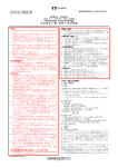
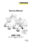
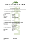
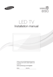
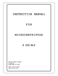
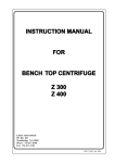
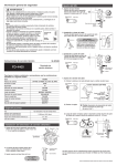
F00022y
Operating Instructions
Series R44LS Discharge Bars
for AC Voltage Operation
BA-e-2003-0302
2
BA-e-2003-0302_R44LS
List of contents
1
Outline of Series R44LS discharge bar for AC
voltage operation
4
2
2.1
2.2
2.3
2.4
2.5
Safety . . . . . . . . . . . . . . . . . . . . . . . . . . . . . . . . . . . . . . . . . . . . . . . 7
Proper use . . . . . . . . . . . . . . . . . . . . . . . . . . . . . . . . . . . . . . . . . . . . 7
Identification of risks and hazards . . . . . . . . . . . . . . . . . . . . . . . . . . 7
Work and operational safety . . . . . . . . . . . . . . . . . . . . . . . . . . . . . . 8
Contact protection . . . . . . . . . . . . . . . . . . . . . . . . . . . . . . . . . . . . . . 9
Technical advance . . . . . . . . . . . . . . . . . . . . . . . . . . . . . . . . . . . . . . 9
3
3.1
3.2
3.3
3.4
3.5
3.6
Installations and assembly . . . . . . . . . . . . . . . . . . . . . . . . . . . . . 10
Length of the high voltage cable . . . . . . . . . . . . . . . . . . . . . . . . . . 10
Assembly of the discharge bar . . . . . . . . . . . . . . . . . . . . . . . . . . . 10
Distance between discharge bar and material surface . . . . . . . . . 12
Impact of temperature radiation . . . . . . . . . . . . . . . . . . . . . . . . . . . 12
Connecting oil and waterfree compressed air supply . . . . . . . . . . 13
Position of the air connections . . . . . . . . . . . . . . . . . . . . . . . . . . . . 14
4
Operation . . . . . . . . . . . . . . . . . . . . . . . . . . . . . . . . . . . . . . . . . . . 15
4.1 Selecting the operating voltage . . . . . . . . . . . . . . . . . . . . . . . . . . . 15
4.2 Function control . . . . . . . . . . . . . . . . . . . . . . . . . . . . . . . . . . . . . . . 15
BA-e-2003-0302_R44LS
5
Maintenance . . . . . . . . . . . . . . . . . . . . . . . . . . . . . . . . . . . . . . . . . 16
6
Troubleshooting . . . . . . . . . . . . . . . . . . . . . . . . . . . . . . . . . . . . . 17
7
Warranty . . . . . . . . . . . . . . . . . . . . . . . . . . . . . . . . . . . . . . . . . . . . 18
8
Technical specifications R44LS . . . . . . . . . . . . . . . . . . . . . . . . . 19
9
Dimensions . . . . . . . . . . . . . . . . . . . . . . . . . . . . . . . . . . . . . . . . . 20
10
Spare parts and accessories . . . . . . . . . . . . . . . . . . . . . . . . . . . 21
3
1. Outline of Series R44LS discharge bar for AC
voltage operation
60
M8
15
16
=
35
M8
AL
=
Fig. 1:
Series R44LS
discharge bar
GL
EL
L
M8
15 5
1
7,535
E
5
241
R60
15
8
L
E
EL
AL
GL
=
=
=
=
=
Z00192y
85
Airchannel
Electrode
Installation length
Active length
Total length
single-row discharge bar,
air knife with air circulation of gas discharge,
emission tip spacing: 15 mm,
active lengths: 15…1995 mm in increments of 15 mm
4
BA-e-2003-0302_R44LS
BA-e-2003-0302_R44LS
5
Dear customer,
The Series R44LS discharge bars have been designed for the active
removal of disruptive static charges during production processes.
The bars are operated with an alternating voltage of 4.8…5.5 kV at
50…60 Hz and are suitable for eliminating static charges on surfaces with
medium to high speeds.
Due to the differences in the surface charge profiles of the various materials, charges of both polarities are supplied by the discharge bars. The
geometric configuration of the corona segment guarantees an ultimate
discharge effect.
The R44LS discharging bars operate with air support and generate an
adequate discharging effect even at larger distance. They improve the
sheet separation from the pile to the copy stream, hold the copy stream in
place at the 90° deviation station and help to improve pile formation.
The air flow ventilation on the inside of the bar allows the unit to be used
under high ambient temperatures of max. 80° with thermal screening and
blast air.
The optimum discharging effect is achieved in combination with Eltex high
voltage supply units with 5 kV AC output voltage.
6
BA-e-2003-0302_R44LS
2. Safety
The Series R44LS discharge bars have been designed, built and tested
using state-of-the-art engineering, and they have left the factory in a technically and operationally safe condition. If used improperly, the bars may
nevertheless be hazardous to personnel and may cause injury or damage.
Read the operating instructions carefully and observe the safety instructions.
Warning!
Do not touch the emission tips of the discharge bar if the supply voltage of
the power supply is switched on. Before cleaning or servicing the bar,
always disconnect the bar from the supply voltage of the power supply
unit.
The manufacturers will not assume any liability and warranty if the bar is
used improperly or used outside the intended purpose.
2.1 Proper use
The Series R44LS discharge bars may only be used for eliminating static
charges on material surfaces. Other uses are not permitted.
The R44LS discharge bars must be operated only in connection with the
dedicated Eltex high voltage supply units with 5 kV AC output voltage.
This will ensure the proper adaptation to the required operating specifications of the various active bar lengths. Safe operation of the electrode
bars is guaranteed only when using the Eltex high voltage supply units
with 5 kV AC output voltage.
Modifications and changes to the discharge bars are not permitted.
Use only original Eltex spare parts and accessories.
2.2 Identification of risks and hazards
Possible risks and hazards resulting from the use of the discharging bars
are referred to in these operating instructions by the following symbols:
Warning!
This symbol appearing in the operating instructions refers to operations
which, if carried out improperly, may result in serious personal injuries.
BA-e-2003-0302_R44LS
7
Caution!
This symbol appearing in the operating instructions refers to operations
which, if carried out improperly, may result in damage to property.
2.3 Work and operational safety
Warning!
Carefully observe the following notes!
• Check the discharge bars and the high voltage cables at regular intervals for any damage. Any damaged components must be repaired or
replaced before continuing to operate the bar, or the appropriate bar or
cable must be disabled.
Make sure that the electrode bars are clean at all times.
• Before carrying out repairs, cleaning or maintenance work, switch off
the power supply unit and disconnect the supply voltage.
• Do not touch the emission tips if the high voltage supply is connected.
Reflex responses to electrical irritation may increase the risk of secondary accidents, especially in the vicinity of unguarded rotating assemblies.
Persons with cardiac pacemakers are always at risk from high voltage
and should take extreme care.
• Mechanical or electrical modifications of the discharge bars are not permitted. Shortening the screened high voltage cable on the connecting
side to the power supply unit is permissible. Lengthening the cable is
only permitted via a suitable terminal box, an original high voltage cable
and suitable cable glands.
• The discharge bars must be repaired, serviced and tested by qualified
personnel only.
• The operation of the electrodes can generate ozone. The ozone concentration levels developing near the electrodes depend on many different factors such as site of installation, electrode stream and voltage,
air circulation, etc., and can therefore not be specified in general terms.
If the maximum allowable concentration (MAC) of ozone must be
observed at the site of installation of the electrode, the concentration
must be measured on site.
8
BA-e-2003-0302_R44LS
2.4 Contact protection
As the installation site or eventual location of the discharge bars is outside
the control of Eltex, a contact protection screen may have to be provided
as specified in the regulations of the employers’ liability insurance associations (e.g. VBG 4 in Germany).
2.5 Technical advance
The manufacturer reserves the right to make changes to the technical
specifications without prior notice in order to adapt the units to state-ofthe- art engineering . Eltex will provide the latest information on any
changes or modifications in the operating instructions on request.
BA-e-2003-0302_R44LS
9
3. Installations and assembly
3.1 Length of the high voltage cable
The high voltage cable is supplied in the following standard lengths:
2.5 / 5 / 7.5 and 10 meters, preassembled.
Special lengths are available on request.
The total length of the discharge bar and of the high voltage cable is limited as the transformer of the power supply unit is under capacitance load
by the cable length. The maximum load capacity is therefore defined as a
function of active bar length and the length of the high voltage cable. The
relationship is shown in Fig. 2.
Σ lengths of active bars [m]
Fig. 2:
Load capacity of
the power supply
units as factor of
active bar length
and length of the
high voltage cable
15
12
10
ES50
ES31
15
7.5
permissible
range
5
permissible
range
5.0
20 30 40 50
Σ lengths of h.v. cable [m]
ES51
permissible
range
10
5
2.5
10
Σ lengths of active bars [m]
5
10 15 20 25
Σ lengths of h.v. cable [m]
10
20 30 40 50
Σ lengths of h.v. cable [m]
Z00193e/Z00050e/Z00041e
Σ lengths of active bars [m]
3.2 Assembly of the discharge bar
The Series R44LS discharge bars must be connected to the machine via
a metal bolted joint. For more convenient installation we recommend
using the assembly and installation material supplied by Eltex (see Fig. 4).
The assembly steps are shown in Fig. 3.
Caution!
The discharge bars must be grounded via the machine potential through
the metal assembly brackets.
The size M8 assembly bolts for attaching the discharge bar to the bracket
must not exceed 12 mm in length. Longer bolts may damage the discharge bar.
Discharge bars with a total length >1500 mm are equipped on the back
with an M8 support plate; three M8 support plates are glued to bars with
lengths >3000 mm. During installation the discharge bars must be supported with these support plates to prevent the bars from sagging.
Failure to observe this mode of attachment may result in mechanical damage to the bars.
Damage of this description is not covered by the warranty.
10
BA-e-2003-0302_R44LS
Caution!
Depending on site of use or location, the discharge bar must be protected
against inadvertent contact by personnel. (Contact protection as specified
in the regulations of the employers’ liability insurance associations.
Please observe all national regulations according this item.
The contact protection device should be made of insulating material such
as GRP or similar material. Contact protection devices made of conductive material must be grounded
7
1
2
8
3
4
5
6
L
E
1
2
3
4
5
6
7
8
BA-e-2003-0302_R44LS
Airchannel
Electrode
Cylinder bolt DIN 912-M8x12-St
Cylinder bolt DIN 84-M8x12-St
Hexagonal nut DIN 933-M8x12-St
Spring washer DIN 127-A8-St
Washer DIN 125-A 8.4-St
Attachment bracket R44 with 2 x longitudinal holes
Max. torque 4 NM, secure with Loctite 243
Max. screw-in depth 4.5 mm
11
Z00194y
E
L
Fig. 3:
Assembly of the
discharge bar with
steel bracket
Fig. 4:
Attachment
accessories
5
40
25
4 R5
60
9
3x45
40
25
4 R5
˚
40
25
60
R44MWS
5
9
3x45
˚
25
40
R44MWM
100
4
R5
120
25
5
9
40
R44MWL
Z00195y
3x45
˚
16
R44MWS: Assembly bracket, small, with a total length of below 1500 mm
R44MWM: Assembly bracket, medium, with a total length of below 1500 mm.
R44MWL: Assembly bracket, large, with a total length of above 1500 mm
3.3 Distance between discharge bar and material surface
The distance between the discharge bar and the material surface must be
selected between 15 and 30 mm.
Discharge bars with air support are used in cases where static charges
impair the separation of piles to feed the copy stream or vice versa. The
distance of the discharge bar from the edge of the pile is 5…20 mm in this
application.
The distance may be ≥20 mm in any other application.
3.4 Impact of temperature radiation
The discharge bar must not be exposed to direct heat radiation which
might lead to an excess of the maximum rated operating temperature of
80 °C. In the event of heat exposure caused by heated moulds and blowing tools, a temperature shield (e.g. a metal plate, approx. 3 mm thickness
or a special plastic material) is required. The metal plate must not be
allowed to rest on the discharge bar and must be grounded.
Discharge bars with air support may also be operated with intermittent air
blasts to prevent the tools from cooling down. The air blast is activated
only, for instance, when the tool opens to discharge the moulding.
12
BA-e-2003-0302_R44LS
3.5 Connecting oil and waterfree compressed air supply
The number of air connections depends on the length of the discharge bar
(see Fig. 5). An internal hose diameter of 9 mm (NW 9) is required to connect the air hose to the air hose joint. The operating pressure must not
exceed 3 bar and must be measured near the air distributor. The distributor crosssection must be dimensioned to match the number of hose connections or in compliance with the consumption volume.
3
4
5
2
6
3
4
2
5
1
6
0
7
bar
7
8
9
8
bar
1
Z00196y
Fig. 5:
Installation of the
compressed air
supply
1
2
3
4
5
6
7
8
9
Pressure gauge
Pressure source
NW 20 hose
Throttle valve
Rota flowmeter
R44LS discharge bar
NW 9 hose (e.g. 4 x 2.5 m)
Distributor
Manometer
Fig. 5 shows the installation diagram for the air supply.
The air distributor is not included with the delivery.
Caution!
If the discharge bar is fitted with several air connections, all hoses from
the distributor to the connecting points must have the same length (identical pressure conditions).
BA-e-2003-0302_R44LS
13
3.6 Position of the air connections
0
E
L
GL
5
≤7
0
GL
A
C
L
E
C
GL
A
GL
A
[mm]
[mm]
GL ≤ 750
GL/2
750 < GL ≤ 1500 125…500
1500 < GL ≤ 2065 250…500
C
[mm]
Z00197y
L
E
Fig. 6:
Dimensions and
position of the air
connections as
factor of total
length GL
5
>7
Number of air connections
250
500
1
2
2
The air connections may also be led outside sideways.
14
BA-e-2003-0302_R44LS
4. Operation
4.1 Selecting the operating voltage
ES50/ES51:
Use the toggle switch to switch on the power supply. In the ON position
the switch lights up green. High voltage is now supplied to the discharge
bars.
The output voltage is now a constant 5 kV AC.
ES31:
If the ES31 power supply is equipped with a potentiometer for setting the
operating voltage (version ES31 VO and ES31 PO), adjust the potentiometer with the power supply switched on until the green signal lamp “Operating Voltage” lights up.
The discharge bar will now be working with the optimum operating voltage
of 5 kV at 50 Hz.
4.2 Function control
ES50/ES51
In general, proper operation is indicated by the illuminated switch in all
units.
ES31
With the ES31 power supply switched on and the discharge bar connected, the signal lamp “Operating Voltage” (ES31 VO and ES31 PO only)
on the power supply lights up.
BA-e-2003-0302_R44LS
15
5. Maintenance
Warning!
Before carrying out any repair, maintenance or service work on the discharge bars and the power supply, switch off the power supply and disconnect the supply voltage. The machine on which the discharge bars are
installed must not be in operation. Repair and maintenance work must be
carried out by qualified personnel only.
In order to ensure the proper function of the discharge bars, clean the bars
at least once per week using compressed air free of oil and water (6 bar,
standard compressed air pistol) and a non-metal brush.
Dirt deposits such as grease, ink, glue, paper dust, etc. must be removed
using a suitable solvent (e.g. cleaning gasoline). Do not soak discharge
bars and high voltage cable in solvent!
When cleaning the discharge bars, switch on the compressed air supply
(1…2 bar) to prevent the air outlet nozzles from clogging up. Allow solvent
to evaporate before resuming operations.
Caution!
Do not damage the emission tips of the discharge bars.
16
BA-e-2003-0302_R44LS
6. Troubleshooting
Warning!
Electric shock hazard!
Before carrying out any repair, maintenance or service work, disconnect
the supply voltage to the power supply.
No high voltage must be applied on the discharge bars.
Repair and maintenance work must be carried out by qualified personnel
only.
Fault
Cause
Remedy
Effectiveness
of application
declines
Dirt settled on bars
Use compressed air and brush to
clean bar. Dirt deposits such as
grease, ink, oil etc. mast be
removed using a suitable solvent
(e.g. cleaning gasoline).
Caution!
Do not soak discharge bars in solvent!
Allow solvent to evaporate before
resuming operations.
Operating
Defective discharge If more than one discharge bar is
voltage lamp
bar. Check bar for
connected to the power supply,
fails to light up any defects which
disconnect one after the other to
may be caused by
localize the defective bar.
creep currents.
Replace defective bar.
Refer to the Power Supplies Operating Instructions for further malfunctions.
BA-e-2003-0302_R44LS
17
7. Warranty
The units are warranted for a period of 12 months provided that the
operating conditions have been maintained, that the units have not been
tempered with and that the units show no mechanical damage.
The warranty applies only if the operating and assembly instructions
specified by Eltex have been observed. The warranty period begins on the
date of delivery.
In the event of defects occurring during the warranty period, the units or
defective components will be repaired at Eltex. Defective components will
be replaced and installed free of charge.
If repairs are required at the customer's premises, the costs for sending a
technician (travel, travel time, expenses) will be charged to the customer.
18
BA-e-2003-0302_R44LS
8. Technical specifications R44LS
BA-e-2003-0302_R44LS
Electrode element
fibre-glass-reinforced polyester GFK UL-94 V-0
Encapsulation
compound
epoxy resin with filler or PU with filler
Assembly material
steel brackets (see Fig. 4)
Creepage resistance
EN 50019 Grade A600
Disruptive strength
60 °C, EN 50028 DIN 53481
Specific volume
resistance
60 °C DIN 53482, 3 x 10¹⁵ Ω x cm
Flammability
V-0 in compliance with UL 94 (1.6 mm) or ISO/R 1210
5...10 sec
Operating
ambient temperature
0...+80 °C (+32...+176° F) (only if blast is in
operation, otherwise 0…+60 °C, (+32…+140 °F)
Ambient humidity
max. 70% relative, no dewing permissible
Emission tips
stainless steel, encapsulated and electrically isolated;
low capacitance and non-sparking
Dimensions
see Fig. 7
Operating voltage
5 kV AC 50/60 Hz
High voltage supply
via Eltex power supplies with 5 kV AC output voltage
Short-circuit current
per tip
approx. 0.055 mA
Contact protection
in compliance with EN 60335, Part 1
Air supply
integrated air profile, air outlet apertures Ø 1mm,
spacing 15 mm, air outlet apertures in special applications Ø 1.5 mm
Air connections
NW 9 mm hose, apparatus air free of oil and water, up
to 40 meters in max. length (see Fig. 6)
Air pressure
max. 3 bar
Air consumption
150…600 l/min per 1 meter of active bar length at
0.1...1 bar air pressure
19
9. Dimensions
60
M8
15
16
=
35
M8
AL
=
Fig. 7:
Series R44LS
discharge bar
GL
EL
L
M8
15 5
1
5
,
7 35
E
5
241
R60
15
8
L
E
EL
AL
GL
=
=
=
=
=
Z00192y
85
Airchannel
Electrode
Installation length
Active length (15…1995 mm in increments of 15 mm)
Total length
20
BA-e-2003-0302_R44LS
10. Spare parts and accessories
BA-e-2003-0302_R44LS
Article
Article number
Assembly bracket R44MWS
Assembly bracket R44MWM
Assembly bracket R44MWL
MCH00011
MCH00002
MCH00009
21
Eltex offices
and agencies
Z01007y
The addresses of all
Eltex agencies can be
found on our website at
www.eltex.com
Eltex-Elektrostatik-Gesellschaft mbH
Blauenstraße 67, D-79576 Weil am Rhein
Phone
+49 (0) 76 21/ 79 05 - 0
Fax
+49 (0) 76 21/ 79 05 - 310
eMail
[email protected]
Internet
www.eltex.com