1
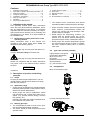
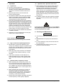
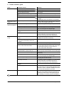
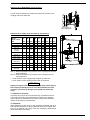
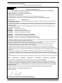
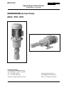
BE6100 Operating Instructions (Translation of original) BRINKMANN-Screw Pump BFS / TFS / FFS Brinkmann Pumpen K. H. Brinkmann GmbH & Co. KG Friedrichstraße 2 D-58791 Werdohl Tel.: +49-2392 / 5006-0 Fax.: +49-2392 / 5006-180 www.BrinkmannPumps.com [email protected] Subject to change without prior notice. Order - No.: BE6100 ENGLISH Brinkmann Pumpen Edition 03/2014 Page 1 of 12 BRINKMANN-Screw Pump Type BFS / TFS / FFS Contents 1 2 3 4 5 6 7 8 Indication to the manual .................................... 2 Description of product and working principle .. 2-3 Safety instructions .......................................... 4-5 Transport and storage ....................................... 5 Installation / Connection ................................. 5-7 Start up / Shut down .......................................... 7 Operation........................................................... 8 Servicing and Maintenance ............................... 8 9 10 11 12 13 Trouble shooter’s guide ..................................... 9 Spare part ....................................................... 10 Repair Instructions ..................................... 10-11 Disposal .......................................................... 11 EC declaration of conformity ........................... 12 The medium moves continuously and without noticeable pulsation toward the pump discharge. 1 Indication to the manual This operating manual gives basic instructions which are to be observed during installation, operation and maintenance of the pump. It is therefore imperative that this manual be read by the responsible personnel and operator prior to assembly and commissioning. It is always to be kept available at the installation site. 1.1 Identification of safety instructions in the operating manual Safety instructions given in this manual noncompliance with which would affect safety are identified by the following symbol Safety sign according with ISO 3864–B.3.1 or where electrical safety is involved, with Safety sign according with ISO 3864–B.3.6 Where non-compliance with the safety instructions may cause a risk to the machine and it’s function the word Proper clockwise rotation must be ensured at all times. Incorrect counterclockwise rotation will result in dry running and pump damage. Catastrophic failure is possible! Screw pumps are self-priming, however, dry running must be avoided under any circumstances as it will almost instantly damage the pump and it might result in catastrophic failure. Screw pumps are positive displacement pumps and must therefore always be used in combination with a pressure limiting valve or pressure relief valve. 2.4 Type code structure (example) High pressure screw pump: Pump series designation BFS, TFS or FFS Pump size Maximum pressure in bar Special features BFS 250 / 80 -G (e.g. with mechanical seal) 2.5 Pump Models ATTENTION BFS, TFS immersion style is inserted. 2 Description of product and working principle 2.1 Scope Pumping of fluids at high backpressure. The discharge pressure needs to be at least 2 bar higher than the inlet pressure. 2.2 Application range Screw pumps are designed for pumping filtered, lubricating fluids (Please consult with the manufacturer for specific applications). Screw pumps are used in applications where high pressures and constant flow rates are required (e.g. general machine design, machine tool industry, etc.) Operate pump within the design limititations and in accordance with section 2.6. FFS foot mounted inline style 2.3 Working principle The intermeshing threads of three screw spindles generate liquid holding chambers. The center spindle is driven and all three screw spindles rotate. BE6100 Edition 03/2014 Page 2 of 12 2.6 Limit of Application ATTENTION Type BFS, TFS, FFS Mediums Oils, cooling / cutting oils coolants Max. delivery pressure 150 bar (200 bar for BFS/FFS1, BFS/FFS2 and TFS/BFS/FFS3 upon request) Minimum discharge pressure Ensure that the discharge pressure is at least 2 bar higher than the inlet pressure Minimum inlet pressure 0.8 bar absolute, (Pumps with a flow rate of greater than 800 l/min have to be operated in conjunction with a feed pump > 1 bar). 1...45 mm /s (cSt) higher viscosities upon request Max. temperature of medium 60 °C over 60 °C on request Max. inlet pressure with mechanical seal < 7 bar Execution -G4 20 bar Concentration of coolant lubricants and water soluble coolants The fluid must have a minimum lubricity in accordance with industry standards. This corresponds to an approx. 4% concentration equivalent to mineral oil. A laboratory analysis is available at the factory. Minimum rpm Dry running Cycle times per hour 2.7 2 Kinetic viscosity of the medium Minimum flow rate The pumps are to be operated within their design limits. Applications outside of these limits are not approved. The manufacturer is not responsible for any damages resulting from use of the pumps in such applications. The minimum flow rate must be large enough to protect the pump from overheating. If necessary, consult with the manufacturer on exact flow rate. 25 Hz (1500rpm), lower rpm are available upon request. The minimum rpm depends on the pressure and medium. The pump MUST never be run dry without fluid. When testing for the direction of rotation, bump the pump for not longer than 1 second. Motors less 3 kW max. 200 from 3 kW to 4.0 kW max. 40 from 5.0 kW to 10 kW max. 20 larger than 10 kW max. 15 Maximum fluid 2 m/s velocity at pump suction Installation positions (Pump must not be installed with motor facing down) Piping / Fittings Pay attention to max. pressure ratings Ambient temperature 40 °C Set-up altitude 1000 m BE6100 Edition 03/2014 Important instructions for screw pumps Never allow screw pumps to run dry! Incorrect rotation will lead to pump damage! Sufficient fluid supply must always be ensured! Large particles in the coolant fluid may damage the screw pump! The limits for size and concentration of foreign particles depends on their hardness! Materials Particle size Particle concentration: Steel / Forgeable aluminium alloys (without Si content) / GG25 < 60 m < 177 mg/l Grey cast iron with hard additives (e.g. GGV) < 50 m < 63 mg/l Ceramic/ corundum / hard metal / glass / CBN Aluminium alloy with Si parts < 20 m < 19 mg/l The particle concentration refers to standardized test. For additional information please refer to the filtration diagram in the screw pump catalogue. ATTENTION If high pressure screw pumps are to be used outside of the recommended ranges, a suitable filter system (e.g. filter bags) must be installed upstream from the pump or pumps with special features must be used (e.g., with coated spindles). If pump failure is caused by excessive wear due to foreign particles, the warranty is void! In applications where hard or abrasive particles are present, the use of coated spindles is highly recommended. 2.8 Technical data Detailed technical data can be found in the screw spindle pump catalogue. Page 3 of 12 3 Safety instructions 3.5 When operating the pump, the safety instructions contained in this manual, the relevant national accident prevention regulations and any other service and safety instructions issued by the plant operator are to be observed. If hot or cold machine components involve hazards, they must be guarded against accidental contact. 3.1 Hazards in the event of non-compliance with the safety instructions Non-compliance with the safety instructions may produce a risk to the personnel as well as to the environment and the machine and results in a loss of any right to claim damages. For example, noncompliance may involve the following hazards: Failure of important functions of the machines/plant Failure of specified procedures of maintenance and repair Exposure of people to electrical, mechanical and chemical hazards Endangering the environment due to hazardous substances being released 3.2 Unauthorized modes of operation Safety instructions relevant for operation Guards for moving parts (e.g. coupling) must not be removed from the machine while in operation. Never subsequently alter any safety devices (e.g. pressure relief valves)! It is necessary to ensure that all safety devices always work properly! Any leakage of hazardous (e.g. explosive, toxic, hot) fluids (e.g. from the shaft seal) must be drained away so as to prevent any risk to persons or the environment. Statutory regulations are to be complied with. Hazards resulting from electricity are to be prevented (see for example, the VDE Specifications and the bye-laws of the local power supply utilities). The pumps’ stability against falling over is not ensured unless it is properly mounted onto the tank or to the floor. The female threads on the motor MUST NOT be used to lift the entire pump and motor assembly. Pump may not be used in potentially explosive environments! Pump and discharge piping are not designed to hold any weight and may not be used as a step ladder. 3.3 Remaining Risk Risk of Injury! Risk of squeezing or crushing body parts when installing or removing the pump exists. Proper and secured lifting tools must be used. Risk of burns! The pump must have cooled down sufficiently prior to commencing any repair, maintenance or installation. 3.6 Safety instructions relevant for maintenance, inspection and assembly work Any work on the machine shall only be performed when it is at a standstill, it being imperative that the procedure for shutting down the machine described in this manual be followed. Pumps and pump units which convey hazardous media must be decontaminated. On completion of work all safety and protective facilities must be re-installed and made operative again. Prior to restarting the machine, the instructions listed under “Start up” are to be observed. 3.7 Signs on the pump It is imperative that signs affixed to the machine, e.g. arrow indicating the direction of rotation symbols indicating fluid connections be observed and kept legible. 3.4 Qualification and training of operating personnel The personnel responsible for operation, maintenance, inspection and assembly must be adequately qualified. Scope of responsibility and supervision of the personnel must be exactly defined by the plant operator. If the staff does not have the necessary knowledge, they must be trained and instructed, which may be performed by the machine manufacturer or supplier on behalf of the plant operator. Moreover, the plant operator is to make sure that the contents of the operating manual are fully understood by the personnel. BE6100 Edition 03/2014 Page 4 of 12 3.8 Unauthorized alterations and production of spare parts Any modification may be made to the machine only after consultation with the manufacturer. Using spare parts and accessories authorized by the manufacturer is in the interest of safety. Use of other parts may exempt the manufacturer from any liability. 4 Transport and storage Protect the pump against damage when transporting. The pumps may only be transported in a horizontal position and hooks or straps must be attached on the motor and pump end. Pumps must be drained prior to their storage. Store pump in dry and protected areas and protect it against penetration of foreign bodies. Always store pump above the freezing point! 5 Installation / Connection 5.1 Mechanical installation Installation The pumps can be mounted either horizontally (foot mounted inline version) or vertically (immersion style) . For safety reasons installations with "motor facing down are not allowed". Pumps must be mounted securely. Piping, tank and pumps must be mounted without any tension. The actual mounting of the pumps depends on size, style and motor used and might be influenced by actual limitations or restrictions on site. In any case, the pumps must always be mounted securely. Pressure side Piping Follow the recommended piping installation guide lines as well as the required tightening torques. Work carried out on high pressure screw fittings, pipes and hoses should only be performed by authorized specialists and must consider the applicable standards and local legislation. Only use components which are rated for high pressure (i.e. no brass)! Do not use fluid sealant or adhesives near the pump or the pressure relief valve (risk of bonding). 35 Pressure limiting valve max. liquid level Pressure relief pipe min. liquid level Connect and disconnect the pressure line only when pump and relief valve are de-energized. H Do not prop up the pressure line via the joining socket. Do not climb onto the pressure line. Connect the suction line, pressure line and positive pressure outflow line as shown in drawing 1, see chapter 7.1. BE6100 Suction side Drawing 1 Edition 03/2014 Page 5 of 12 In the case of a G4 execution, the leakage connection must be piped without back pressure (see drawing 2) and routed back into the tank in a nonpressurised state. The connection MUST never be closed or valved off. Pressure relief valves (DBV’s) Always protect screw pumps against pressure overload, -do not use screw pumps without pressure relief valves! When operating pressure relief valves, it is forbidden to operate the pump above the stated nominal pressure. Check the function of the pressure relief valve after Ionger downtimes. replace damaged parts if necessary. G4 execution Keep leakage hole open also see section ‘Piping’ ATTENTION Defective pressure relief valves may lead to pump damage. Excess pressure can also damage other system components or cause human injuries. Drawing 2 Pressure Gauge Briefly open shutoff valve at the pressure gauge to check for proper supply pressure, then close again. The shutoff valve protects the pressure gauge from pressure surges, which may damage the pressure gauge. Piping No pipes or fittings mounted to the pump system should not put any physical stress on the pump components. Avoid any unnecessary changes in pipe crosssections or in pipe direction (this can cause noise). The nominal pipe diameters may not be smaller than the nominal diameter of the pump suction and discharge. Clean all pipes, fittings and fixtures: remove burr and welding beads; clean tanks thoroughly. Flange gaskets must not protrude inside into the pipe. Make sure that NO metal chips or fines can fall into the tank after initial pump installation (e.g. drilling holes in tank lid for name plate mounting, etc). Air relief valve 5.2 The installation of an air relief valve at the highest point of the discharge pipe is recommended. Attention! If the end of the discharge piping is located below the clean tank in a closed loop arrangement the clean tank may drain due to the elevation difference. This can be avoided by installing check valves or air relief valves. Electric wiring All service work must be carried out by qualified service personnel. Pump must be disconnected from the power source and all rotating parts must stand still. Reassure that pump is disconnected from power source and cannot be switched on. Verify that there is no voltage at the terminal board ! BE6100 Edition 03/2014 Page 6 of 12 The motor is surface-cooled and compliant with DIN IEC 34 and EN 60034 (protection degree IP 55). According to the European Standard EN809 a motor overload must be installed and properly set to the full load amps stated on the pump name plate. It is the responsibility of the machine operator to decide whether or not an additional emergency switch must be installed. 5.2.1 6 Start up / Shut down 6.1 Circuit Tension voltage and frequency must correspond with the shown specification on the nameplate. The pump must be wired so that a solid longterm electrical connection is ensured. Establish a solid ground connection. The electrical wiring must be performed according to the wiring diagram shown inside the terminal box cover. (Please see above sample wiring diagrams) ATTENTION The motor’s direction of rotation must correspond with the pump’s directional arrow (direction of rotation is clockwise with a view onto the fan cover). Check the pumps operation with 2 people, i.e. 1 person should start the motor as recommended (running for 1 sec. max.) and the other person should monitor the direction of the motor. It is not permitted to run the pump without any medium (dry run). This can damage the pump. Do not put defective pumps back into operation! Check suction and pressure pipes for any leaks; avoid admission of air into the pump system. Monitor pressure and temperature monitoring devices frequently. Wiring diagram e.g. Star connection (Standard up to 5.5 kW) 3 x 400 V, 50 Hz resp. 380-420 V, 50 Hz 6.2 resp. Delta connection (Standard as of 7.5 kW) 3 x 400 V, 50 Hz resp. 380-420 V, 50 Hz Turn off Turn off motor. For longer downtime periods, dismantle and preserve pump 6.3 Standard motors are operated in the delta connection but can also be started up with a star-delta start up unit in order to reduce the in rush current. In this case, make sure you start up the pump with minimal back pressure, as otherwise the pump may run backwards when switching over from star to delta! There may be no foreign objects such as dirt, particles or humidity inside the terminal board. Mount terminal board cover to motor tight against dust and humidity and close up all unused wiring ports. ATTENTION When Variable Frequency Drives are used interfering signals might occur. Non-sinus shaped supply voltage from a variable frequency drive might result in elevated motor temperatures. BE6100 Start up / Turn motor on Open all valves in discharge line completely and de-energize pressure relief valve (start up pump without any backpressure). Ensure sufficient liquid level in tank. In case of a horizontal installation, the pump must be filled prior to initial start-up. After connecting the electrical wires, close the terminal box, switch on the motor and check for the direction of rotation in the following manner: Shut down All service work must be carried out by qualified service personnel. Pump must be disconnected from the power source and all rotating parts must stand still. Reassure that pump is disconnected from power source and cannot be switched on. Verify that there is no voltage at the terminal board! Turn off motor Open terminal box and disconnect the power leads. Close all valves! Empty out the pump. Remove all materials which could potentially cause harm to humans or the environment! Coolants must not pollute the environment! Depressurize the system! When handling toxic materials, wear safety glasses, protective clothing and protective gloves! Edition 03/2014 Page 7 of 12 7 Operation 7.4 7.1 Liquid level Check for proper liquid level. The minimum liquid level (H, see drawing 1) should be 70 mm for BFS1, BFS2, and TFS3, 100 mm for TFS4 and TFS5 and 150 mm for TFS6. Maximum liquid level is 35 mm below the pump’s mounting plate. The distance between the suction pipe and the bottom of the tank is 100 mm for BFS1, BFS2, TFS3, TFS4 and TFS5 and 150 mm for TFS6. These distances must be adhered to. Using the patented Brinkmann suction protector prevents large particles and foreign objects from entering the screw pump. The protector extends the life expectancy of the pumps significantly. In addition, the large surface area of the suction protector prevents the pump from drawing air which can be caused by a funneling effect at the suction pipe if no suction protector is used. The pump may only be installed and operated in a suitable container! Operation is only permitted with a suction pipe, suction line or suction protector. Never operate screw pumps dry. Sufficient fluid level must always be ensured. 7.3 Signs of abnormal operating behaviour Discolouration, noises and vibrations in the vicinity of the adaptor cap point to problems with the main drive spindle bearing. In order to avoid hazards, the pump should be put out of service immediately! In addition, please follow the separate operating instructions for the pressure relief valve (jointly supplied). 8 Servicing and Maintenance ATTENTION 7.2 When operating with a pressure relief valve the user should bear in mind that the self-setting operating pressure depends on the flow rate, especially in the case of spring-controlled valves. As such, the operating pressure should not be insignificantly above the opening pressure of the valve. The motor power is to be adequately rated according to the maximum prevailing pressure. If the pump becomes blocked, do not operate the pump any longer (see point 6.3) and send it to the manufacturer for repair. ATTENTION Operation with a pressure relief valve The surface of the motor must be kept free of dirt. BRINKMANN-Screw pumps are maintenance free. In case of damage, pump must be sent back to the manufacturer. Unauthorized repair work or opening of the pump will void all warranties! When the pump noise increases, this indicates to a medium with insufficient lubricity, or wear and tear. If the noise increases to a level which is no longer permitted or in the case of strong vibrations, the pump should be exchanged immediately. Operation with a frequency inverter When operating with a frequency inverter, the user must ensure that it has a safety reserve of 10% in terms of the nominal voltage of the motor. In addition, the size of the motor should provide a safety margin of 10 % with respect to the max. pump output. When operating with a frequency inverter it is necessary to follow the permitted minimum speeds and maximum speeds. These depend on the pressure, medium and pump model. If necessary, consult with the factory. Please follow the separate operating instructions for the frequency inverter (jointly supplied). BE6100 Edition 03/2014 Page 8 of 12 9 Trouble shooter’s guide Fault Possible causes Remedy Pump does not pump Incorrect direction of rotation of pump Reverse direction of rotation of motor. Pump is operating without fluid Add pumping fluid; raise fluid level in tank. Shut-off valves are closed Open valves All fluid is pumped through a bypass line Check bypass lines and relief valve settings. Broken pressure relief valve Replace pressure relief valve, check pressure. Pump is blocked Exchange pump immediately. Do not turn the motor on again! Send the pump to the manufacturer to be repaired. Pump does not deaerate No possibility for de-aeration provided Install air relief valve in the discharge line or start up pump with de-energized relief valve. Pump does not operate at full capacity Suction line is leaking Tighten the flange screw fittings and replace seals. A bypass is in open Check the piping and correct the bypass / leakage. Suction pipe too close to tank bottom Use Brinkmann suction protector; shorten suction pipe; cut suction pipe at 45 degree angle Upstream or downstream filters clogged Clean or replace filter. The pump is worn out If necessary, improve the filtration. If you are familiar with the equipment, exchange the spindle set. Otherwise, send the pump to the manufacturer. Suction line is leaking; pump is drawing air Tighten fittings and pipe connections; replace seals or gaskets in suction line if necessary. The suction height is greater than 1.2 m and/or the total input pressure is < 0.8 bar. Raise fluid level in tank or lower pump. System pressure is too low Check the size of the primary pressure pump. Incorrect opening and closing sequence of the suction side valves Correct the valve opening sequence so that the pump only starts when the valve is open. Only close the valve when the pump no longer rotates. In general, avoid suction side valves. Air pockets or air entrainment in the pumped medium or pump sucks air. Ensure that air is discharged better in the container. Check the proper seal/connection of the suction pipe. Resistance in suction line too high Increase suction pipe diameter; check for restrictions (elbows etc.) Suction pipe too close to tank bottom Use Brinkmann suction protector; shorten suction pipe; cut suction pipe at 45 degree angle Fluid viscosity too high Feed screw pump by secondary feed pump after consulting with the manufacturer The pump is worn out If necessary, improve the filtration. If you are familiar with the equipment, exchange the spindle set. Otherwise, send the pump to the manufacturer. Upstream or downstream filters clogged Clean or replace filter Auxiliary equipment causes noises Noises can also arise as a result of defective pressure relief valves, an unfavourable path taken by the pipework or a lack of ventilation. Establish the source of the noise and eliminate the root cause. Pump is operating loudly Inline pump is leaking The ring seal is worn out or soiled Otherwise, send the pump to the manufacturer in order for it to be repaired. Check the equipment for hydraulic shock and suction side negative pressure when switching. If necessary, improve the filtration. : Will result in immediate pump damage or hazards BE6100 Edition 03/2014 Page 9 of 12 10 Spare part 10.1 Pump design Item Description 10.2 Indications to the spare part order Spare parts are available from the supplier. Standard commercially available parts are to be purchased in accordance with the model type. The ordering of spare parts should contain the following details: 1. Pump Type e.g. TFS364/60 2. Pump No. e.g. 03146100 The date of the construction year is a component of the pumps type number. 3. Voltage, Frequency and Power Take item 1, 2 and 3 from the nameplate. 4. Spare part with item No. e.g. Motor 1 1 Motor 2 Screw pump 3 Bell housing 4 Motor coupling hub 5 Coupling spider 6 Pump coupling hub 7 Set screw Friedrichstraße 2 D-58791 Werdohl 11 Repair Instructions 11.1 Fitting the coupling Coat pump and motor shaft ends with a thin coat of Molykote (e.g. Molybdenumdisulfphite) and insert the woodruff key. Slide the pump coupling hub (6) onto the pump shaft by using a rubber mallet. Move pump coupling hub down as showing in following table and drawing. If the hub installation is too difficult, warming up the coupling hubs will simplify the hub installation. Secure the pump coupling hub (6) using the set screw (7) Clean motor shaft with solvent to remove any anti-rust coatings. Then coat the motor shaft with a thin layer of Molykote (e.g. Molybdenumdisulfphite) and insert the woodruff key. Slide the motor coupling hub (4) onto the motor shaft to dimension as shown in following table (Page 11) and drawing Secure the motor coupling hub (4) using the set screw (7). BE6100 Edition 03/2014 Page 10 of 12 Dimensions for BFS1/BFS2 (2 pole motors): In each case the distance is measured by the inner surface of the coupling hub to the shaft end Inner surface of the coupling hub Dimensions for TFS3, TFS4 and TFS5 (2 pole motors): TFS3 Power 50 Hz / 60 Hz kW A TFS4 B C mm mm mm A TFS5 B C mm mm mm A B C mm mm mm 2.2 / 2.55 -1 0 165 -1.5 -1.5 170 3.0 / 3.45 +4.6 0 183 0 0 183 4.0 / 4.6 +4.6 0 183 0 0 183 5.5-7.5 / 5.75-8.6 -2 -2 196 0 +5 210 +1 0 220 11.0-18.5 / 12.6-21.3 +7 +15 256 +7 +10 256 0 +3 256 22.0 / 24.5 +7 +13 256 +7 +8 256 0 +1 256 30.0 / 33.5 0 +19 256 30.0-37.0 / 33.5-41.5 0 +15 256 +1 0 256 45.0 / 51.0 0 +21 262 0 +7 262 55.0 / 62.0 +2 +6 295 75.0-90.0 / 84.0-101 -34 +30 295 Inner surface of the coupling hub Dim. A: Distance between inner surface of the coupling hub and the motor shaft end Dim. B: Distance between inner surface of the coupling hub and pump shaft end + = Inner surface of the coupling hub is higher as shaft end - = Inner surface of the coupling hub is lower as shaft end ATTENTION High axial impact loads on both pump and motor shafts during the coupling assembly process are to be avoided at all costs in order to prevent any damage to the pump and motor bearings. 11.2 Repairs to the pump In general, the pumps do not need servicing or maintenance and only need to be sent to the manufacturer in order to be repaired. Upon request, the manufacturer provides training and information sheets on the subject of spindle sets. 12 Disposal When disposing of the pump or the packaging materials the local and national regulation for proper disposal must be complied with. Prior to its disposal, the pump must be completely drained and decontaminated if necessary . BE6100 Edition 03/2014 Page 11 of 12 13 EC declaration of conformity DEUTSCH / ENGLISH /FRANÇAIS / ESPAÑOL EG-Konformitätserklärung EC declaration of conformity / Déclaration de conformité CE / Declaración de conformidad CE Hersteller / Manufacturer / Constructeur / Fabricante Brinkmann Pumpen, K. H. Brinkmann GmbH & Co. KG Friedrichstraße 2, D-58791 Werdohl Produktbezeichnung / Product name / Désignation du produit / Designación del producto Hochdruckpumpen / High Pressure Pumps / Pompes à haute pression / Bombas de alta presión Typ / Type / Tipo BFS, TFS, FFS Das bezeichnete Produkt stimmt mit den folgenden Richtlinien des Rates zur Angleichung der Rechtsvorschriften der EG-Mitgliedsstaaten überein: The named product conforms to the following Council Directives on approximation of laws of the EEC Member States: Le produit sus-mentionné est conforme aux Directives du Conseil concernant le rapprochement des législations des Etats membres CEE: El producto designado cumple con las Directivas del Consejo relativas a la aproximación de las legislaciones de los Estados Miembros de la CEE: 2006/42/EG 2006/42/EC 2006/42/CEE 2006/42/CEE Richtlinie für Maschinen Council Directive for machinery Directive du Conseil pour les machines Directivas del Consejo para máquinas 2004/108/EG 2004/108/EC 2004/108/CEE 2004/108/CEE Richtlinie für elektromagnetische Verträglichkeit Council Directive for Electromagnetic compatibility Directive du Conseil pour Compatibilité électromagnétique Directivas del Consejo para Compatibilidad electromagnética Hinsichtlich der elektrischen Gefahren wurden gemäß Anhang I Nr. 1.5.1 der Maschinenrichtlinie 2006/42/EG die Schutzziele der Niederspannungsrichtlinie 2006/95/EG eingehalten. With respect to potential electrical hazards as stated in appendix І No. 1.5.1 of the machine guide lines 2006/42/EG all safety protection goals are met according to the low voltage guide lines 2006/95/EG. Conformément à l'annexe I N° 1.5.1 de la Directive "Machines" (2006/42/CE) les objectifs de sécurité relatifs au matériel électrique de la Directive "Basse Tension" ont été respectés. Con respecto al potencial peligro eléctrico como se indica en el apéndice I No. 1.5.1 del manual de la máquina 2006/42/EG, todos los medios de protección de seguridad se encuentran según la guía de bajo voltaje 2006/95/EG. Die Übereinstimmung mit den Vorschriften dieser Richtlinien wird nachgewiesen durch die vollständige Einhaltung folgender Normen: Conformity with the requirements of this Directives is testified by complete adherence to the following standards: La conformité aux prescriptions de ces Directives est démontrée par la conformité intégrale avec les normes suivantes: La conformidad con las prescripciones de estas directivas queda justificada por haber cumplido totalmente las siguientes normas: Harmonisierte Europ. Normen / Harmonised Europ. Standards / Normes europ. harmonisées / Normas europ. armonizadas EN 809 EN ISO 12100 EN 60204-1 EN 61000-3-2 EN 61000-3-3 EN 61000-6-2 EN 61000-6-3 Nationale Normen / National Standards / Normes nationales / Normas nacionales: EN 60034-1 Die Hinweise in der Betriebsanleitung für den Einbau und die Inbetriebnahme der Pumpe sind zu beachten. The instructions contained in the operating manual for installation and start up the pump have to be followed. Les indications d’installation / montage et de mise en service de la pompe prévues dans l’instruction d’emploi doivent être suivies. Tenga en cuenta las instrucciones en el manual para la instalación y puesta en marcha de la bomba. Brinkmann Pumpen, K. H. Brinkmann GmbH & Co. KG Werdohl, 20.03.2014 ............................................................................................... Norbert Burkl Leiter Qualitätssicherung / Manager of quality assurance Directeur d’assurance de la qualité / Director del aseguramiento de calidad BE6100 Edition 03/2014 Page 12 of 12