1
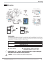
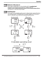
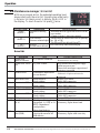
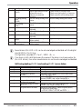
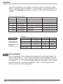
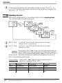
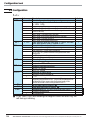
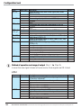
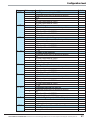
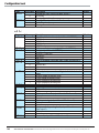
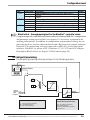
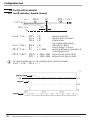
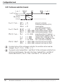
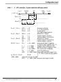
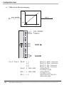
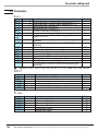
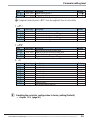
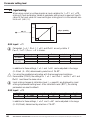
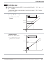
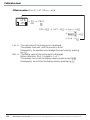
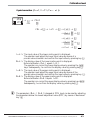
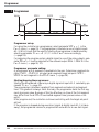
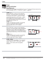
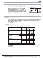
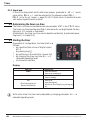
Operation
The control parameters can be determined from the values calculated for delay
time Tu , maximum rate of increase vmax, control range Xh and characteristic K according to the formulas given below. Increase Xp, if line-out to the set-point oscillates.
Parameter adjustment effects
Parameter
Control
Pb1 higher increased damping
lower
reduced damping
td1 higher reduced damping
lower
increased damping
ti1 higher increased damping
lower
reduced damping
Line-out of disturbances
Start-up behaviour
slower line-out
slower reduction of duty cycle
faster line-out
faster reduction of duty cycle
faster response to disturbances faster reduction of duty cycle
slower response to disturbances slower reduction of duty cycle
slower line-out
slower reduction of duty cycle
faster line-out
faster reduction of duty cycle
Formulas
K = Vmax * Tu
controller behavior
PID
With 2-point and
PD
3-point controllers,
the cycle time must be PI
P
adjusted to
t1 / t2 0,25 * Tu 3-point-stepping
Pb1 [phy. units]
1,7 * K
0,5 * K
2,6 * K
K
1,7 * K
td1 [s]
2 * Tu
Tu
OFF
OFF
Tu
ti1 [s]
2 * Tu
OFF
6 * Tu
OFF
2 * Tu
3.7 Alarm handling
Max. three alarms can be configured and assigned to the individual outputs. Generally, outputs OuT.1... OuT.3 can be used each for alarm signalling. If more
than one signal is linked to one output the signals are OR linked. Each of the 3 limit values Lim.1 … Lim.3 has 2 trigger points H.x (Max) and L.x (Min), which
can be switched off individually (parameter = “OFF”). Switching difference
HYS.x of each limit value is adjustable.
Alarm handling
18
Operating KS4x-1
ACS-CONTROL-SYSTEM GmbH l Lauterbachstr. 57 l D-84307 Eggenfelden l www.acs-controlsystem.de l [email protected]
18