1
Operating Instructions
for MIHM-VOGT Laboratory Furnaces
with Controller P6
MIHM-VOGT GmbH & Co. KG, Friedrich-List-Str. 8, D-76297 Stutensee-Blankenloch, Tel.: +49/7244/70871-0, Fax: +49/7244/70871-20
MIHM-VOGT GmbH & Co. KG, Friedrich-List-Str. 8, D-76297 Stutensee-Blankenloch, Tel.: +49/7244/70871-0, Fax: +49/7244/70871-20
Operating Instructions
for
MIHM-VOGT Laboratory Furnace
with Controller P6
Table of contents:
1.
2.
3.
4.
5.
6.
7.
8.
9.
Index
Delivery form
Use area
Technical data
Safety warning
Installation and electrical connection
Start-up
6.1 Start-up
6.3 Service of the controller
6.3.1 Function keys
6.3.2 Setting of individual programs
6.3.3 Examples of programming
6.3.4 Setting of individual text
6.3.5 Starting of a program
6.3.6 Start of a program with the delay start feature
6.3.7 Optional step (Final temperature)
6.3.8 Continuous operation of the rear sockets in case of shock-heat investments
Special functions
7.1 Information at starting
7.2 Function key 'F'
7.3 Correction program
7.4 Cooling function with exhaust blower / circulating air (version 1.20 and later)
7.5 Controller initialisation
7.6 How to connect exhaust blowers, catalyzers and/or fume extraction hoods
Error signals
8.1 Error messages of the electronics
8.2 Further errors and their causes
Maintenance and care
9.1 Care
9.2 Maintenance
9.2.1 How to change the thermocouple
9.2.2 How to change the heating muffle
9.2.3 How to change the door-stone
9.2.4 How to replace the controller
9.2.5 How to replace the power element of the 2 nd heating circuit
(only for furnace types BL, TL)
9.2.6 How to change the air circulation fan
9.3 Warranty
9.4 Circuit diagrams
4
4
5
5
6
6
6
7
7
7
9
13
13
14
14
15
17
17
18
18
19
19
19
21
21
21
22
23
23
23
24
24
24
25
25
25
27
28
MIHM-VOGT GmbH & Co. KG, Friedrich-List-Str. 8, D-76297 Stutensee-Blankenloch, Tel.: +49/7244/70871-0, Fax: +49/7244/70871-20
GB
-4-
Dear customer,
We thank you for your decision to buy a high-quality MIHM-VOGT furnace. It will support you
with your work for many years, because it was developed and built using the latest
technology.
Improper use can cause damage, therefore we ask you to carefully read through this
working instructions and to follow it.
The CE-sign confirms that MIHM-VOGT laboratory furnaces correspond to the
governing regulations of the EC guidelines.
1.
Delivery form
Each laboratory furnace is delivered with a P6-controller, a ceramic tray, a PtRh-Pt
thermocouple and an exhaust tube.
The furnace can also be equipped with the folling accessories:
•
Exhaust blower DG2 (Art. No. 7202)
•
Catalyzer KN (Art. No. 7300)
•
Catalyzer for shock-heat investments KN2 (Art. No. 7320)
Spareparts
Furnace type:
2.
Order No.:
KM
SL
GL
BL
TL
Ceramic tray
20020
30020
40020
50020
50020
Thermocouple
20100
30110
30110
50110
30110
Door filling (w ithout ventilator)
20301
30301
30301
30301
30301
Door filling (w ith ventilator)
20351
30301
30301
30301
30301
Heating muffle (w ithout ventilator)
20010
30010
40010
50010
60010
Heating muffle (w ith ventilator)
20015
30015
40015
50015
60015
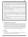
Use area
The laboratory furnace is used to eliminate wax and to preheat the dental casting ring.
The heating muffle is made of high-quality heating wire and is heated evenly on four
sides. The low electric burden guarantees a high lifespan of the heating wire. A highquality inner isolation ensures low power consumption.
At the rear of the furnace two sockets are provided allowing connection of an exhaust
blower, a catalyzer, or a fume extraction hood.
MIHM-VOGT GmbH & Co. KG, Friedrich-List-Str. 8, D-76297 Stutensee-Blankenloch, Tel.: +49/7244/70871-0, Fax: +49/7244/70871-20
GB
-5-
The furnace door is equipped with a switch that interrupts the heating current when
opening the door. The P6-controller is equipped with a thermocouple circuit breaker
so that the furnace does not overheat if the thermocouple is defective. At the rear of
the furnace the furnace type is imprinted on a label.
3.
Technical data
Ofentyp:
KM
SL
GL
BL
TL
Outside
dimensions:
40 x 48 x 40
43 x 58 x 45
48 x 58 x 52
54 x 60 x 55
54 x 65 x 55
w x h x d (cm)
40 x 48 x 45
43 x 58 x 51
48 x 58 x 59
54 x 60 x 62
54 x 65 x 62
Heating chamber:
w x h x d (cm)
15 x 10 x 17
18 x 11 x 19
20 x 11 x 25
25 x 11 x 28
25 x 17 x 28
4 pcs. of 6x
4 pcs. Ø 8 cm
6 pcs. Ø 8 cm
9 pcs. Ø 8 cm
18 pcs. Ø 8 cm
1150 °C
1150 °C
1150 °C
1150 °C
1150 °C
1100 °C
1100 °C
1100 °C
1100 °C
1100 °C
1.6 kilowatts
1.8 kilowatts
2.3 kilowatts
3.5 kilowatts
4.5 kilowatts
1.6 kilowatts
2.1 kilowatts
2.6 kilowatts
3.7 kilowatts
4.8 kilowatts
Voltage:
230 V~
230 V~
230 V~
230/400 V~
(2/N)
230/400 V~
(2/N)
Preheating times:
60 min.
900 °C
60 min.
800 °C
60 min.
800 °C
60 min.
800 °C
60 min.
800 °C
90 min.
1050 °C
90 min.
1100 °C
90 min.
1100 °C
90 min.
1100 °C
90 min.
1100 °C
32 kg
63 kg
75 kg
90 kg
100 kg
36 kg
70 kg
80 kg
95 kg
105 kg
Capacity:
Max. Temperature:
Power rating:
Weight:
furnaces with circulating air
4.
Safety warning
•
The MIHM-VOGT laboratory furnace is exclusively designed for the elimination of wax
and for the preheating of casting rings. We are not liable for damages due to another
use. The sockets at rear are exclusively intended for the connection of a MIHM-VOGT
fume extraction hood, a MIHM-VOGT exhaust blower, or a MIHM-VOGT catalyzer.
•
The MIHM-VOGT laboratory furnace must be serviced exclusively by technicians who
know the content of this working instructions. Labels and stickers on the laboratory
furnace must always be maintained in legible condition. They must not be removed.
MIHM-VOGT GmbH & Co. KG, Friedrich-List-Str. 8, D-76297 Stutensee-Blankenloch, Tel.: +49/7244/70871-0, Fax: +49/7244/70871-20
-6-
•
GB
The MIHM-VOGT laboratory furnace should be set up only in dry areas and should not
get in contact with liquids. In the area of the furnace, furniture and other objects cannot
consist of explosive, combustible or easily inflammable materials. In the installation
area of the furnace, no easily inflammable or combustible gases or liquids are
allowed to be stored.
•
Modifications of the MIHM-VOGT laboratory furnace can only be made after prior
written agreement from us. We are not liable for damages caused by your
modifications. Before every maintenance, the appliance is to be turned off and the
power-supply plug is to be pulled out.
•
The furnace must always be connected to a separate circuit protected by a 15/16 Amp
fuse.
•
The hot furnace door should only be touched at the grip; the hot muffles should only
be touched with sufficiently long tongs. Because of the wax fumes and the steam
from casting rings, the furnace should be equipped with an exhaust blower or
catalyzer and placed under a fume extraction hood. The fumes are to be extracted to
the outside.
•
The ceramic tray is to be used to protect the heating muffle. The furnace must never
be used without the ceramic tray. Cracked or damaged ceramic trays must be
replaced immediately.
•
The transportation protection of the heating muffle must be taken off before the first
use.
5.
Installation and electrical connection
The laboratory furnace is to be positioned in a dry area in accordance with the safety
warnings, and it is to be connected to a separated circuit secured with 15/16 Amp.
The transportation protection is to be removed from the heating muffle. The laboratory
furnaces type KM, SL and GL are to be connected to an earthed plug 230 V, the
laboratory furnaces type BL and TL are to be connected to a CEKON plug 230/400 V
AC. If necessary, the exhaust blower DG2 or the catalyzers KN / KN2 are installed on
the furnace rear. They are to be connected into the socket marked 'Gebläse'.
6.
Start-up
6.1
Start-up
Prior to the first use, the muffle must be heated up on 1050°C for 90 minutes. This
way, the necessary oxide layer is formed on the heating wire.
MIHM-VOGT GmbH & Co. KG, Friedrich-List-Str. 8, D-76297 Stutensee-Blankenloch, Tel.: +49/7244/70871-0, Fax: +49/7244/70871-20
GB
-7-
6.2 Loading
The casting muffles are to be put on the ceramic tray. Metal muffle rings should not
come in contact with the lateral walls.
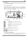
6.3
Service of the controller
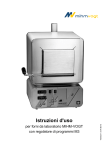
The time-schedule controller is equipped with the most modern microprocessor
technology, that allows the heating process to go through a wide variety of programs
with precision. The furnace is programmed on a menu-driven keyboard with LCD
indicators. The following functions are available:
LCD display
Program step
key s
Numerical
key s
1
2
3
4
5
6
7
8
9
F
0
Start/Stop
key
On/Of f
switch
Function
key
6.3.1
Load
program
key
Memory
key
Casting
time key
Function keys
Start/Stop key: to start or stop the current program
Load program key: to load a program from the memory
Memory key: to store a program entered into memory
Casting time key: to set the casting time
Function key: to set the parameters
6.3.2
...
Numeric keys: to enter the values desired
...
Program step keys: to activate the cursor
Setting of individual programs
Immediately after switching on the furnace, a display appears indicating information
on the system. Within a few seconds the stand-by display appears instead:
MIHM-VOGT GmbH & Co. KG, Friedrich-List-Str. 8, D-76297 Stutensee-Blankenloch, Tel.: +49/7244/70871-0, Fax: +49/7244/70871-20
GB
-8-
Example:
°C/min
°C
min
3
1050
0
0
6
520
4
280
30 STNDBY
P01
S4
0 TEMP.
22
S3
10 MO
12:13
S2
30 MO
18:32
S1
On the left side, the furnace program is indicated where lines 'S1' to 'S4' stand for the
according steps 1 to 4 to be programmed accordingly. In the column '°C/min' the
heating speed is determined, in '°C' the temperature is set, and in the column 'min'
the delay of the according step is indicated. The furnace is heated in up to four
temperature steps. It is possible to heat and cool down within one program. There
are no preset programs when leaving the factory.
Individual programs are entered as follows:
1.)
Choosing of a program number / Loading of a porgram:
After activating the load program key, the display "load program" appears. The cursor
is set to the field "program number". Now the program number desired is either
entered by the numeric keys or searched by scrolling down using the 'S4' key.
LOAD PROGRAM
P13
S4
S3
YES
S2
NO
S1
Pressing the 'S2' key activates the loading process = 'yes', then the stand-by display
appears. To quit the menu earlier, press 'S1' = 'no'.
2.)
Entering of a program:
On pressing 'S1' the cursor shows up in the column '°C/min'. The numeric keys ('0' '9') are used to enter the heating speed. Then the cursor moves on to the column '°C'.
Here a 4-digit holding temperature has to be entered (e.g.: '0280'). If only a 3-digit
value (or less) is entered, 'S1' has to be pressed to confirm it and to move the cursor
to the column 'min'. There the holding time is determined.
Steps 'S2' to 'S4' are programmed in the same way. If one step is not required, set all
values in this line on '0'.
MIHM-VOGT GmbH & Co. KG, Friedrich-List-Str. 8, D-76297 Stutensee-Blankenloch, Tel.: +49/7244/70871-0, Fax: +49/7244/70871-20
GB
-9-
°C/min
°C
min
3
1050
0
0
6
520
4
280
30 STNDBY
P01
S4
0 TEMP.
22
S3
10 MO
12:13
S2
30 MO
18:32
S1
IMPORTANT: Steps 'S1' to 'S3' may be set to '0'; however, in step 'S4' a certain
temperature must be entered. Choosing '0' as heating speed ('°C/min'), the furnace
heats up at maximum energy (non-linear).
3.)
Storing of a program:
After entering a program via the keys 'S1' to 'S4', the memory key is to be pressed to
store the according data. The display indicates the following menu:
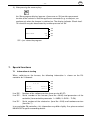
STORE PROGRAM
P13
S4
S3
YES
S2
NO
S1
Data is stored by pressing the 'S2' key = 'yes'. Pressing 'S1' = 'no' stops the menu,
and the stand-by display appears again.
The program is stored under that program number which was entered on loading.
6.3.3
Examples of programming
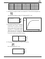
Example of programming: 3-step heating
Heating speed
Temperature
Holding time
°C/min.
°C
Min.
Step 4:
0
850
60
Step 3:
0
0
0
Step 2:
6
540
15
Step 1:
4
280
45
°C
540
280
15 min.
850
45 min.
1.) Selection of the program numb er
(e.g. No. '01'): Press the load program
key
MIHM-VOGT GmbH & Co. KG, Friedrich-List-Str. 8, D-76297 Stutensee-Blankenloch, Tel.: +49/7244/70871-0, Fax: +49/7244/70871-20
Time
GB
- 10 -
and enter the program numb er '01'. Confirm b y pressing 'S2' = 'yes'.
LOAD PROGRAM
P01
S4
S3
YES
S2
NO
S1
2.) Pressing the 'S1' key lets the cursor show up in the field '°C/min.' = heating speed.
Enter '4' using the numeric keys. Then, the cursor automatically goes on to the
field '°C' = temperature. Enter '0280' here; the cursor automatically goes to the field
'min' = holding time. Here '45' is to b e entered. (In case just '280' was entered in
the temperature field, this value has to b e confirmed with the 'S1' key.)
°C/min
°C
min
0
0
0 STNDBY
P01
S4
0
0
0 TEMP.
22
S3
0
0
0 MO
12:13
S2
4
280
45 MO
15:45
S1
3.) Steps 'S2' and 'S4' are set in the same way. Since in this example step 'S3' is not
required, all values are set to '0' in this line.
°C/min
°C
min
0
850
0
0
6
540
4
280
60 STNDBY
P01
S4
0 TEMP.
22
S3
15 MO
12:13
S2
45 MO
18:32
S1
4.) The program is stored b y pressing the memory key,
confirm with 'S2' = 'yes'.
STORE PROGRAM
P01
S4
S3
YES
S2
NO
S1
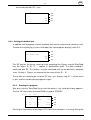
Example of programming: Shock heat
Heating speed
Temperature
Holding time
°C/min.
°C
Min.
MIHM-VOGT GmbH & Co. KG, Friedrich-List-Str. 8, D-76297 Stutensee-Blankenloch, Tel.: +49/7244/70871-0, Fax: +49/7244/70871-20
GB
- 11 -
Step 4:
0
850
0
Step 3:
0
0
0
Step 2:
0
0
0
Step 1:
0
0
0
1.) Selection of a program numb er, for example No. 2: Press the load program key
and enter the Program numb er '02'. Confirm with 'S2' = 'yes'.
LOAD PROGRAM
P02
°C
S4
S3
YES
S2
NO
S1
850
2.) Pressing the 'S4' key lets the cursor
show up in field '°C/min.' = heating
speed. Enter '0' using the numeric
keys or press 'S4' to move to the
next field '°C' = temperature. Enter
'0850' here; the cursor automatically
Time
°C
goes to the field 'min' = holding time. Here '0' is to b e entered. Alternatively, the 'S4'
key may b e used to move to the next field.
°C/min
°C
min
0
850
0 STNDBY
P02
S4
0
0
0 TEMP.
22
S3
0
0
0 MO
12:13
S2
0
0
0 MO
13:05
S1
5.) The program is stored b y pressing the memory key,
then confirmed with 'S2' = 'yes'.
STORE PROGRAM
P02
S4
S3
YES
S2
NO
S1
MIHM-VOGT GmbH & Co. KG, Friedrich-List-Str. 8, D-76297 Stutensee-Blankenloch, Tel.: +49/7244/70871-0, Fax: +49/7244/70871-20
GB
- 12 -
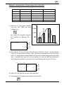
Example of programming: 3-step heating with cooling step
Heating speed
Temperature
Holding time
°C/min.
°C
Min.
Step 4:
0
430
60
Step 3:
0
1050
60
Step 2:
6
540
15
Step 1:
4
280
45
and enter the program numb er
'03'. Confirm b y pressing 'S2' =
"yes".
LOAD PROGRAM
P03
280
S4
60 min.
540
60 min.
1050
15 min.
°C
45 min.
1.) Selection of a program numb er
(e.g. No. '03'): Press the load
program key
Time
S3
YES
S2
NO
S1
2.) Pressing the 'S1' key lets the cursor show up in the field '°C/min.' = heating speed.
Enter '4' using the numeric keys. Then, the cursor automatically moves on to the
field '°C' = temperature. Enter '0280' here; the cursor automatically goes to the field
'min' = holding time. Here '45' is to b e entered. (In case just '280' was entered in
the temperature field, this value has to b e confirmed b y pressing the 'S1' key.)
°C/min
°C
0
430
0
1050
6
540
4
280
min
60 STNDBY
P03
S4
22
S3
15 MO
12:13
S2
45 MO
20:24
S1
60 TEMP.
3.) Steps 'S2', 'S3' and 'S4' are set in the same way.
4.) The program is stored b y pressing the memory key
MIHM-VOGT GmbH & Co. KG, Friedrich-List-Str. 8, D-76297 Stutensee-Blankenloch, Tel.: +49/7244/70871-0, Fax: +49/7244/70871-20
GB
- 13 -
and confirmed with 'S2' = 'yes'.
STORE PROGRAM
P03
S4
S3
YES
S2
NO
S1
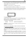
6.3.4 Setting of individual text
In addition to the program stored, individual text may be entered and stored as well.
Therefor the memory key is pressed to open the store program display (see 6.3.2):
STORE PROGRAM
P13
S4
INDIVIDUAL TEXT
S3
YES
S2
NO
S1
The 'S3' key lets the cursor show up in the according line. By pressing the 'Start/Stop'
key, the letters 'A', 'B', 'C', ... appear in alphabetical order. The letter needed is
confirmed with 'S3'. This process may be continued until the text desired is complete
(max. 19 letters). Figures are entered via the numeric keys '0' ... '9'.
These data are stored by pressing the 'S2' key = 'yes'. By pressing 'S1' = 'no' the menu
is quit, and the stand-by display appears again.
6.3.5
Starting of a program
After pressing the 'Start/Stop' key to start the process, the stand-by display appears.
The line 'S4' now shows the word 'RUN' instead of 'STNDBY'.
°C/min
°C
min
0
750
0
0
6
520
4
280
60 RUN
P09
S4
22
S3
10 MO
12:13
S2
30 MO
18:32
S1
0 TEMP.
Flashing or illumination of the stage-LCD shows that a process is running. During the
MIHM-VOGT GmbH & Co. KG, Friedrich-List-Str. 8, D-76297 Stutensee-Blankenloch, Tel.: +49/7244/70871-0, Fax: +49/7244/70871-20
GB
- 14 -
process, the stages passed are deleted when finished. The process may be stopped
by pressing the 'Start/Stop' key.
The current temperature is indicated in line 'S3'. Line 'S2' shows the actual time (and
day), and line 'S1' indicates the expected end of the program.
6.3.6
Start of a program with the delay start feature
First, the program desired is loaded via the load program key (see 6.3.3). When
pressing the casting time key, the following information appears on the display:
AUTOST..P13
TEMP.
FR 01:25
S4
22
S3
DO
12:13
S2
FR
07:30
S1
│
│
Process start
Casting time
Pressing the 'S1' key allows to determine the casting time desired (= program end).
The day is set at first using the numeric keys (Monday = 1, Tuesday = 2, Wednesday =
3, ... Sunday = 7). Then the program end desired (hh:mm) is entered via the numeric
keys. In the left column of line 'S1' the display then shows the program's start time .
The delay start feature is now activated; no more keys are to be pressed.
6.3.7
Optional step (Final temperature)
If casting muffles for different final temperatures, e.g. for 750 C and 850 °C, are to be
preheated at the same time, set the temperature for the 3rd step on 750 °C as
described under 6.3.3. The program is changed by a long pressure on the 'S4' key
after completion of the first program. The temperature in the 3rd step can now be
raised, e.g. to 850 °C. The controller automatically repeats the last heating step and
then heats up to the new temperature set (850 °C). The final temperature may be
changed as often as required. The original parameters of the program remain
untouched.
Alternatively it is possible to extend the according holding time of the last step which
is recommended especially in case of shock-heat investments. Therefor the furnace
is heated up as follows:
Example:
0
750
0
0
0
0
0
0
0 RUN
P09
S4
22
S3
10 MO
12:13
S2
30 MO
12:55
S1
0 TEMP.
MIHM-VOGT GmbH & Co. KG, Friedrich-List-Str. 8, D-76297 Stutensee-Blankenloch, Tel.: +49/7244/70871-0, Fax: +49/7244/70871-20
GB
- 15 -
An acoustic signal is audible as soon as the final temperature of 750 °C is reached.
Now the shock-heat muffles are placed into the furnace. By pressing the 'S4' key the
holding time is extended as follows:
0
750
0
0
0
0
0
0
60 RUN
P09
S4
22
S3
10 MO
12:13
S2
30 MO
12:55
S1
0 TEMP.
The 60 minutes entered start running now. When finished, an acoustic signal sounds
again, and the muffles are ready to be cast.
WARNING: Do not interrupt the program by pressing the „Start/Stop“ key!
6.3.8
Continuous operation of the rear sockets in case of shock-heat
investments
A P6-controller with software version 02.55 and later (see information of the controller
as per 7.1 of these working instructions) allows to individually program the sockets on
continuous function when using shock-heat investments.
It is sensible to use an exhaust blower, a catalyzer or a fume extraction hood therefor
ensuring that these appliances are running as long as the muffles are in the furnace.
Especially if a catalyzer is used, this function guarantees that it reaches its optimum
operating temperature.
Continuous operation of the sockets at the P6-controller is activated, when storing a
program (see topic 6.3.2 of the P6 instructions), by a pressure on the 'S4' key. The
display then indicates 'Shock heat':
STORE PROGRAM
S13
S4
S3
SHOCK HEAT
YES
S2
NO
S1
This function may be deactivated by another pressure on the 'S4' key.
Data is stored by pressing the 'S2' key = 'yes'. Pressing 'S1' = 'no' stops the menu,
and the stand-by display appears again.
MIHM-VOGT GmbH & Co. KG, Friedrich-List-Str. 8, D-76297 Stutensee-Blankenloch, Tel.: +49/7244/70871-0, Fax: +49/7244/70871-20
GB
- 16 -
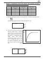
Example of programming: Shock heat program with continuous operation of
catalyzer (or exhaust blower or fume extraction hood)
Heating speed
Temperature
Holding time
°C/min.
°C
Min.
Step 4:
0
850
0
Step 3:
0
0
0
Step 2:
0
0
0
Step 1:
0
0
0
1.) Selection of a program numb er, for example No. 2: Press the load program key
and enter the program numb er '02'. Confirm with 'S2' = 'yes'.
LOAD PROGRAM
P02
S4
S3
YES
S2
NO
S1
2.) Pressing the 'S4' key lets the cursor
show up in field '°C/min.' = heating
speed. Enter '0' using the numeric
keys or press 'S4' to move on to the
next field '°C' = temperature. Enter
'0850'
here;
the
cursor
automatically moves to the field
°C
850
'min' = holding time. Here '0' is to
b e entered. Alternatively, the 'S4'
key may b e used to move to the
next
field.
°C/min
°C
Time
°C
min
0
850
0 STNDBY
P02
S4
0
0
0 TEMP.
22
0
0
S3
0 MO
12:13
S2
0
0
0 MO
13:05
S1
MIHM-VOGT GmbH & Co. KG, Friedrich-List-Str. 8, D-76297 Stutensee-Blankenloch, Tel.: +49/7244/70871-0, Fax: +49/7244/70871-20
GB
- 17 -
3.) After pressing the memory key
the 'Store program display' appears. A pressure on 'S4' provides permanent
tension at the sockets so that the appliances connected, e.g. a catalyzer, run
continuously when the furnace is switched on. The display indicates 'Shock heat'.
This function may b e deactivated b y another pressure on 'S4'.
STORE PROGRAM
S02
S4
S3
SHOCK HEAT
YES
S2
NO
S1
'S2' = 'yes' stores the program.
7.
Special functions
7.1
Information at starting
When switching on the furnace, the following information is shown on the P6controller for 3 seconds:
Line 'S3':
Line 'S2':
Line 'S1':
MIHM-VOGT
S4
V02.57
S3
P6B-SN:
43843/1
S2
DOSB-SN
4240/7
S1
Number of the software version (here version 02.57)
Serial number of the furnace (here No. 43843) and parameters of the
controller (here controller parameter 1 = KMP6, 2= SLP6 ... TLP6)
Serial number of the electronics (here No. 4240) und hardware version
(here No. 7)
In case of older P6-controllers, this information may differ slightly. If so, please contact
MIHM-VOGT to get the according details.
MIHM-VOGT GmbH & Co. KG, Friedrich-List-Str. 8, D-76297 Stutensee-Blankenloch, Tel.: +49/7244/70871-0, Fax: +49/7244/70871-20
GB
- 18 -
7.2
Function key 'F'
Function key 'F' is used to adjust the individual requirements of your P6-controller.
THU
Key 'S4':
Key 'S3':
Key 'S2':
Key 'S1':
Key 'S4':
Key 'S3':
Key 'S2':
Key 'S1':
ENGLISH
S4
SOUND ON
S3
12:13
S2
NEXT
S1
With 'S4' the display language is changed.
An acoustic signal indicates the end of the program. If you do not want this
acoustic signal in general, you may turn it off by pressing the 'S3' key. (The
acoustic signal also stops when opening the door of the furnace).
With 'S2' the integrated clock is set where Monday = 1, Tuesday = 2 ...
Sunday = 7. The current time is to be altered manually with the
summer/winter time switch!
'S1' is used to go on further:
AIRDROME TEMP
600
S4
BLOWER TEMP
600
S3
NETWORK
OFF
S2
NEXT
S1
Airdrome temperature at the socket marked 'Dunst' [standard = 600 °C]
Blower temperature at the socket marked 'Gebläse' [Standard = 600 °C]
This key is only needed if the controller is furnished with an interface to be
connected to a network.
This key is used to quit the menu and to store the settings made.
ATTENTION (Regarding software version 02.54 or b efore): If shock-heat investments
are used and an exhaust blower, a catalyzer or a fume extraction hood are connected,
the shutoff temperature of the sockets 'Dunst' (= exhaust) or 'Gebläse' (= ventilator)
should be approximately 20 °C higher than the programmed final temperature for the
shock-heat investment (example: If the final temperature for shock-heat investments
is 850 °C, the shutoff temperature should be at 870 °C). Thus, the above mentioned
appliances run continously when the furnace is switched on.
7.3
Correction program
The calculation of the start time (casting time function for the delay start feature is
based on an average tension of 230V. Start and finishing times may vary according to
local voltage. Severe variations (of more than 30 minutes) may be adjusted by means
of the correction program.
MIHM-VOGT GmbH & Co. KG, Friedrich-List-Str. 8, D-76297 Stutensee-Blankenloch, Tel.: +49/7244/70871-0, Fax: +49/7244/70871-20
GB
- 19 -
The correction program is accessed by loading the program '00'. In case of older P6models (software version 01.xx), the correction program is stored as No. '99'. The
correction program itself may not be altered.
ATTENTION: The complete program lasts approximately 8 hours!
7.4
Cooling function with exhaust blower / circulating air (version 1.20 and later)
At the end of the program, pressing the 'S2' key activates the exhaust blower, if
connected, and pressing the 'S1' key switches on the air circulation fan for a fast
cooling process (only possible in case of furnaces with integrated air circulation).
DOOR OPEN
TEMP.
7.5
S4
800
S3
BLOWER
ON
S2
CIRCULATING AIR
ON
S1
Controller initialisation
In order to guarantee optimal performance with the various laboratory furnaces,
different parameters are preset . The controller is reset to factory settings with the
following keystroke, and the according parameters are activated:
The furnace must indicate 'STNDBY':
•
Keystroke:
'F' '8' '5' '4' '0'
parameters of furnace types KM
•
Keystroke:
'F' '8' '5' '5' '0'
parameters of furnace types SL .. TL
ATTENTION: The controller parameters may not be altered without agreement of
MIHM-VOGT, Karlsruhe/Germany!
7.6
How to connect exhaust blowers, catalyzers and/or fume extraction hoods
a.) Connection of an exhaust blower:
The exhaust blower type DG2 is inserted into the designated space at the back and
fixed at the rear sheet metal with the according screws. If an exhaust pipe is
connected, this has to be removed. Connect the plug at the rear socket marked
'Gebläse'.
If required, the exhaust blower can be extended up to approx. 3 - 5 m using
conventional metal pipes (with a diameter of 80 mm at least). Please see to it that the
air resistance is kept low (make only a few angles and do not use flaps) since
otherwise the air flow in the blower might change its direction and, thus, suction
stops.
MIHM-VOGT GmbH & Co. KG, Friedrich-List-Str. 8, D-76297 Stutensee-Blankenloch, Tel.: +49/7244/70871-0, Fax: +49/7244/70871-20
GB
- 20 -
In case of shock-heat investments, please ensure that the blower runs throughout the
complete preheating process of the casting muffles. If required, the shutoff
temperature of the sockets have to be changed (see point 6.3.8 and 7.2).
b.) Connection of a catalyzer:
The adapter supplied for the catalyzer type KN or KN2 is inserted into the designated
space at the back and fixed at the rear sheet metal using the according screws. If an
exhaust pipe is connected, this has to be removed. The suction pipe of the catalyzer
has to be attached to the adapter and secured with the counter screw. Connect the
plug at the rear socket marked 'Gebläse'.
It is recommendable to operate the catalyzer under a fume extraction hood exhausting
the fumes either into a chimney or to the outside. The catalyzer may be extended in
the same way as a blower; then an additional ventilator (type ZL, order No. 73010, or
type ZL2, order No. 73210) must be installed inside the pipe. With this measure, the
catalyzer's pipe may be extended up to approx. 3 - 5 m (diameter for KN 120 mm at
least, diameter for KN2 150 mm at least). Please see to it that the air resistance is
kept low (make only a few angles and do not use flaps) since otherwise the air flow in
the blower may change its direction.
In case of shock-heat investments, please ensure that the blower runs continuously
throughout the complete preheating process of the casting muffles. If required, the
shutoff temperature of the sockets has to be changed (see points 6.3.8 and 7.2).
In dental technology, gases of burnt wax (= organic hydrocarbons) are the main
components which are emitted when heating investments or casting muffles. These
gases are burnt again in the catalyzer and split into carbon dioxide (CO2) and water
steam (H2O). In case of higher temperatures, some investments may release also
ammonia gases which the catalyzer transforms into different nitrogen oxides (NOx).
As not all manufacturers of investments and waxes give complete information on
additional components, it is impossible to name all remainders of other contents
released and their composition.
c.) Connection of a fume extraction hood:
A fume extraction hood used together with the laboratory furnace can be controlled via
the socket marked 'Dunst'. Using shock-heat investments requires continuous
operation of the fume extraction hood during the complete preheating process of the
casting muffles. The shutoff temperature of the rear sockets might have to be altered
(see points 6.3.8 and 7.2). If the fume extraction hood is controlled by several
furnaces, a furnace adapter / relay connection must be used:
MIHM-VOGT f urnace adapter:
f urnace control only
with switch:
furnace control / mains control
Connection of up to 3 f urnaces:
OA3, Art. No.: 7553
OA31, Art. No.: 7555
Connection of up to 4 f urnaces:
OA4, Art. No.: 7554
OA41, Art. No.: 7556
MIHM-VOGT GmbH & Co. KG, Friedrich-List-Str. 8, D-76297 Stutensee-Blankenloch, Tel.: +49/7244/70871-0, Fax: +49/7244/70871-20
GB
- 21 -
8.
Error signals
8.1
Error messages of the electronics
If errors occur, an according error message is indicated in the display accompanied
by an acoustic signal.
Error signals:
Cause:
Elimination:
"Sensor defekt"
T hermocouple connections are
loose.
Check thermocouple connections.
T hermocouple defective.
Change the thermocouple.
T hermocouple is incorrectly
attached.
Shift thermocouple connections.
"Sensor + <-> -"
T emperature inside the heating Open the door and wait until the
muffle is significantly below
heating muffle has reached room
room temperature.
temperature.
Automatic switchoff as a
safety feature
8.2
Furnace temperature exceeds
1200 °C.
Switch off the furnace manually as
well and let cool down. Call the
customer service.
Further errors and their causes
Error signals:
Cause:
Elimination:
Controller shows wrong
time
Wrong time on the controller.
Correct time in accordance with
point 7.2.
Malfunction of the
heating speed
T he 'Start/Stop' key was pressed Enter a new program with final
by accident.
temperature as the only parameter.
Heating has not started
although autostart
program runs
Power was out during autostart
program.
Controller indicates: "Door Door-switch sticks or is
open" when door is shut.
defective.
Check the power connection and
ensure that no timer is interposed.
Check door-switch. Call customer
service if necessary.
Error signals:
Cause:
Elimination:
Light-emitting diode at
the controller indicates
heating but furnace does
not heat.
Heating muffle is defective
(measure resistance of the
heating muffle with ohmmeter
[Ro.k.= 18 .. 30 Ω]).
Heating muffle is defective. Change
it. Call customer service if
necessary.
Controller is defective.
Replace the controller. Call
customer service if necessary.
Power element is defective
(furnace type BLP6[-U] or
T LP6[-U] or older P6 version).
Replace the power element. Call
customer service if necessary.
MIHM-VOGT GmbH & Co. KG, Friedrich-List-Str. 8, D-76297 Stutensee-Blankenloch, Tel.: +49/7244/70871-0, Fax: +49/7244/70871-20
GB
- 22 -
9.
Controller "forgets" the
programs stored.
Controller is defective.
Replace the controller. Call
customer service if necessary.
Controller "forgets" the
time
Controller is defective.
Replace the controller. Call
customer service if necessary.
Displays are not working.
Yellow pilot light of
On/Off switch is on. LCDs
just flash at switching on.
Display of the controller is
defective.
Replace the controller. Call
customer service if necessary.
Displays are not working.
Yellow pilot light of
On/Off switch is on. LCDs
do not flash at switching
on.
Protection fuse of the furnace is P6/B:
defective.
T urn off the furnace, wait for 30
seconds, switch on again. If this
does not help, replace the
controller. Call customer service if
necessary.
P6 (older versions):
Remove the controller and check
the fuse in the fuse holder on the
board.
Displays are not working.
Yellow pilot light of
On/Off switch is off.
No mains voltage.
Check fuses in the circuit breaker
box, check connection
management. Call customer service
if necessary.
DG2, KN, or KN2 is
connected but not
working.
Attachment has no tension.
Check fuses in the furnace sockets as
well as parameter settings (function
key 'F') of the attachments.
DG2, KN, or KN2 do not
work. Fumes are not
extracted.
Air resistance in the exhaust
pipe is too high.
Check exhaust pipe. Enlarge size, if
necessary, and/or insert an
additional ventilator.
Fume extraction hood is
connected but not
working.
Fume extraction hood has no
tension.
Check fuses in the furnace sockets as
well as parameter settings (function
key 'F') of the attachments.
Furnace activates the
circuit breaker in the
switchbox
If the furnace is equipped with
a catalyzer, the catalyzer may
be defective.
Pull the catalyzer plug out of the
socket. If the circuit breaker is now
no longer activated, the heating of
the catalyzer may be defective;
return the catalyzer for repair.
Because of wax fumes, too
much carbon has settled in the
insulation; leakage current
flows from the heating to the
housing activating the circuit
breaker.
T o burn the carbon in the
insulation, the furnace is connected
to a plug that is not protected by a
circuit breaker, heated up on 1050
°C and held for approx. 3 hours.
If this does not help, change the
insulation and call customer service
if necessary.
Maintenance and care
MIHM-VOGT GmbH & Co. KG, Friedrich-List-Str. 8, D-76297 Stutensee-Blankenloch, Tel.: +49/7244/70871-0, Fax: +49/7244/70871-20
GB
- 23 -
9.1
Care
•
The chamber area should be kept clean. The ceramic tray is to be used and
must not be cracked.
•
The muffles are to be put into the furnace so that no contact with the walls exists.
•
The furnace is to be heated up empty on 1050 °C before the first use; this
temperature is to be held for 1.5 hours (= 90 minutes). This process should be
repeated, especially if the furnace is used to burn out wax, every 14 days in the
first three months of operation. Later, repeat this process every four weeks.
•
If the furnace is used to burn out wax, it is recommended to use an exhaust unit
or a catalyzer to evacuate the wax steams.
9.2
Maintenance
Warning:
Turn off the furnace and pull out the power-supply plug before every maintenance!
Attention:
The laboratory furnace insulation (lining) contains ceramic fibre / aluminium silicate
fibre particles. According to the EU classification of December 5, 1997, this fibre must
be declared as “carcinogen category 2 according to EU Directive 97/69/EC”
(substances to be regarded as carcinogenic for humans). Animal experiments have
shown that high exposure to dust can cause diseases of the lung or pleura in the
form of fibrosis or cancer. These findings have not been confirmed in human studies.
Critical health impairment is unlikely if the recommended instructions for use and
valid limit values are observed.
Examples for European limits:
Country
Germany
France
Limit
0,5 F/ml
0,6 F/ml
Origin
TRGS 900
Circulare DRT nr. 95-4 du 12.01.95
Great Britain
2,0 F/ml
HSE - EH40, maximum exposure limit
It is unlikely that these limit values will be reached during servicing of the laboratory
furnace. It is nevertheless recommended that respiratory masks type FFP2 are worn
on a voluntary basis.
9.2.1
How to change the thermocouple
MIHM-VOGT GmbH & Co. KG, Friedrich-List-Str. 8, D-76297 Stutensee-Blankenloch, Tel.: +49/7244/70871-0, Fax: +49/7244/70871-20
- 24 -
GB
•
Pull the power-supply plug out!
•
Only for furnace with circulating air: unscrew the protection covering the motor of
the ventilator.
•
Loosen the connections of the thermocouple head. Unscrew the thermocouple
from the rear wall and take it out.
•
9.2.2
Insert the new thermocouple and screw it on the rear wall. Connect the new
thermocouple correctly: red cable at +, white cable at -!
How to change the heating muffle
•
Pull the power-supply plug out!
•
Only for furnace with circulating air: unscrew the protection covering the motor of
the ventilator. Take out the ventilator as described under 9.2.6.
•
Unscrew upper and lower rear wall. Loosen the connnection of the heating
wires in the sub box.
•
Carefully take out the insulating material. Pull out the heating muffle carefully.
•
Put in the new heating muffle, (IMPORTANT: for furnace type BL, put the ceramic
tray in the heating muffle before introducing the heating chamber!). Connect the
new heating muffle.
•
Put the insulation material back and fix the upper and lower wall again.
•
For furnace with circulating air only: install the air circulation fan as described
under 9.2.6. Screw on the protective cover of the fan motor.
9.2.3
•
9.2.4
How to change the door-stone
Loosen the cross-recessed screw and remove the hold sheet metal. Take out
the door-stone.
How to replace the controller
•
Pull the power-supply plug out!
•
Loosen the cross-recessed screws from the front electronic (controller
component) and take it out.
•
Remove plugs and plug-in strips at the controller. Loosen the thermocouple
connection wire. Proceed accordingly in reverse order to put in the new front
electronic unit. Do not mix up the thermocouple connections
(red = „+“, white = „-“).
MIHM-VOGT GmbH & Co. KG, Friedrich-List-Str. 8, D-76297 Stutensee-Blankenloch, Tel.: +49/7244/70871-0, Fax: +49/7244/70871-20
GB
- 25 -
9.2.5
How to replace the power element of the 2
furnace types BL, TL)
nd
heating circuit (only for
•
Pull the power-supply plug out!
•
Take the ceramic tray out of the heating chamber, put the furnace on its side,
unscrew the metalplate at the bottom.
•
Remove the plug-in strips from the power element and unscrew it.
•
Proceed accordingly in reverse order for reassembly.
9.2.6
•
How to change the air circulation fan
Pull the power-supply plug out!
Laboratory furnace type KM:
•
Unscrew the cover of the fan.
•
Unscrew the mounting sheet metal with the fan from the rear wall. Take those
and the heating muffle out.
•
Reverse the procedure to reassemble the air circulation fan. Propeller should
not be overtightened. It must be able to run freely. File the hole if necessary.
Laboratory furnace type SL... TL:
•
Unscrew the cover of the ventilator. Extract the protection basket in the heating
chamber.
•
Hold tightly the motor of the ventilator and unscrew the propeller in the heating
muffle from the motor axle. WARNING: anti-clockwise threads! If Propeller axle
should be stuck, spray it with penetrating oil and let work. Call customer service
if necessary.
•
Unscrew the ventilator motor at rear.
•
Reverse the procedure to reassemble the air circulation fan. Propeller should
not be overtightened. It must be able to run freely. File the hole if necessary.
9.3 Warranty
1.
2.
Mihm-Vogt guarantees, under the following conditions, that its dental appliances are
free of defects in accordance with the latest technological findings for the appliance in
question for a period of 12 months from delivery of the appliance by the specialist
dealer, provided that this occurs no later than six months after delivery from the
factory.
The warranty covers only the repair of the dental appliance free of charge by a MihmVogt specialist dealer. The parts incorporated in the appliance during the repair will
be subject to the same warranty as that of the appliance itself until expiry of said
MIHM-VOGT GmbH & Co. KG, Friedrich-List-Str. 8, D-76297 Stutensee-Blankenloch, Tel.: +49/7244/70871-0, Fax: +49/7244/70871-20
- 26 -
3.
4.
5.
GB
warranty in accordance with No. 1. Replaced parts will become the property of MihmVogt.
Guarantee claims are to be submitted with the invoice to a Mihm-Vogt specialist
dealer who will carry out the repair.
Wear and tear, particularly to wear parts such as heating elements, bulbs, fans, and
thermo-elements, are not covered by the warranty.
Guarantee claims will not be accepted if a defect is connected with
a)
the effect of external mechanical or chemical influences on the appliance
b)
c)
6.
7.
8.
improper or excessive use of the appliance
repair, maintenance or servicing by a third party whom the end user knows not to
be a Mihm-Vogt specialist
d)
incorporation in the appliance of parts whose use has not been approved by
Mihm-Vogt or which change the appliance in a way not approved by Mihm-Vogt
e)
failure to observe the instructions by Mihm-Vogt on the handling, servicing and
care of the appliance (e.g. operating instructions), in particular if the scheduled
services are not carried out
f)
failure by the end user to notify a defect and have it repaired as described in
No. 3 immediately in the case of defects that were apparent at the time of
delivery of the appliance or immediately on detection in the case of defects that
became apparent later.
Recommendations for use, irrespective of whether they are given orally, in writing or
during practical instruction, are based on experience and tests by Mihm-Vogt and can
therefore be regarded as guidelines only. Mihm-Vogt products are subject to further
development. Mihm-Vogt therefore reserves the right to make changes in design and
composition.
All guarantee claims expire at the end of the warranty period defined in No. 1. For
claims made but not rectified during the warranty period, the expiry date is extended
until the defect has been rectified. In this case the warranty expires two months at the
latest after the last repair or statement by the Mihm-Vogt specialist dealer that the
defect has been remedied or did not exist.
Claims by the purchaser against the supplying dealer are unaffected by this warranty.
MIHM-VOGT GmbH & Co. KG
January 2009
MIHM-VOGT GmbH & Co. KG, Friedrich-List-Str. 8, D-76297 Stutensee-Blankenloch, Tel.: +49/7244/70871-0, Fax: +49/7244/70871-20
- 27 -
GB
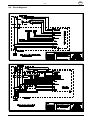
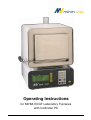
9.4 Circuit diagrams
MIHM-VOGT GmbH & Co. KG, Friedrich-List-Str. 8, D-76297 Stutensee-Blankenloch, Tel.: +49/7244/70871-0, Fax: +49/7244/70871-20
GB
- 28 -
Index
A
D
Acoustic signal
Adapter
Additional ventilator
Air circulation fan
Airdrome temp
'Dunst'
Fumes
Automatic switchoff
Autostart
17
19
19
24
17
17
17
20
13
B
Blower
Blower temp
'Gebläse'
18
18
18
C
Care
Casting time
Casting time key
Catalyzer
Ceramic fibre
Ceramic tray
CE-sign
Change
Air circulation fan
Controller
Door-stone
Heating muffle
Power element
T hermocouple
Circuit breaker
circuit diagram
Circulating air
Clock
Connection
Catalyzer
Catalyzer
Exhaust blower
Fume extraction hood
Continuous operation
Controller
Initialisation
Controller information
Controller initialisation
Controller parameters
Controller performance
Cooling function
Correction program
Cursor
22
13, 18
7
4, 6, 15, 19
22
4
4
24
23
23
23
23
23
21
26
17
17
19
19
19
19, 20
15
6, 23
18
17
18
17, 18
18
18
18
8
Delay start feature
Delivery form
DG2
Door filling
Doorstone
13, 17
4
18
4
23
E
Electrical connection
Enter
Casting time
Day
Finishing time
Error
Automatic switchoff
Autostart
Catalyzer
Circuit breaker
Display
Door open
Exhaust blower
Fume extraction hood
Heating
Heating speed
Sensor defective
T hermocouple defective
T ime
Error messages
Error signals
Example
7, 9,
Examples
Examples of programming
3-step heating
3-step heating with cooling step
Shock heat
Exhaust blower
4, 6, 14,
6
13
13
13
20,
12,
10,
17,
20
20
21
21
21
20
21
21
21
20
20
20
21
20
20
14
15
9
9
11
10
18
F
Final temperature program changes
Finishing time
Fume extraction hood
Function key
Functions
Furnace adapter
13
13
4, 14, 20
7, 16
6
20
H
Heating
Heating
Heating
Heating
Holding
Holding
muffle
speed
step
wire
temperature
time
4, 23
8
13
4
8
8, 13
MIHM-VOGT GmbH & Co. KG, Friedrich-List-Str. 8, D-76297 Stutensee-Blankenloch, Tel.: +49/7244/70871-0, Fax: +49/7244/70871-20
GB
- 29 -
I
Individual programs
Individual text
Information
Start time
Installation
7
12
16
6
Program '00'
Program '99'
Program number
Program step key s
Programming
17
17
8
7
6
R
Relay connection
K
Key
1 ... 9
Casting time
F 5, 14
Load program
Loading
Memory
S1 ... S4
Start/Stop
Store program
Key board
KN
KN2
S
7
7
7, 9, 10, 15
11
10, 11,12
7, 9, 10, 11, 15
7
7
6
19
19
L
Language
Load program key
Loading
Local v oltage
16
7, 9, 10, 11, 15
6
17
M
Maintenance
Memory key
22
7, 10, 11, 12
N
Network
Non-linear
Numeric key s
20
17
8
7
Safety warning
Schnittstelle
Sensor
Sensor defective
Serial number
Service
5
17
20
20
16
Controller
Setting of text
Shock-heat investments
Software version
Spareparts
Special functions
Stand-by
Stand-by display
Start time
Start/Stop key
Start-up
Store program key
Summer time
6
12
13, 14, 19
16
4
16
7
7
13, 16
7
6
7
16
T
T echnical Data
T hermocouple
T ime
T ransportation protection
5
4, 23
16
6
U
O
Use area
Operating temperature
Optional step
14
13
V
Voltage
P
Pipe
Power consumption
Power element
Process run
Program
Entering
Indiv idual
Loading
Start
Storing
19
4
23
12
8
8
7
8
12
8
4
18
W
Warranty
Winter time
25
16
Z
ZL
ZL2
MIHM-VOGT GmbH & Co. KG, Friedrich-List-Str. 8, D-76297 Stutensee-Blankenloch, Tel.: +49/7244/70871-0, Fax: +49/7244/70871-20
19
19