1
Page
1e
Issue 02.06
LiPoBalancer Operating Instructions, Software V1 and later
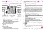
Safety circuit is active (conductive) when
green „EIN“-LED is glowing
Safety-sockets for looped-through charge lead.
„+“ charge lead (red)
to be connected there.
8 / 14 red cell-count-LEDs
indicate balancing process
This cable must be
plugged into the „+“
socket on the battery charger.
Battery type select
Jumper
Li-Po
Li-Io
(no jumper = Li-Fe
or as configured
via RS232)
Schulze BalCab20
balancer-socket
for 2s ... 8s packs
resp. 2s ... 14s packs
Ideal for
Schulze LiPoPerfekt
battery packs
RS232 - interface (COM - port) Conventional balancer - socket
for exporting charge data and 7-pin JST connector for 2s ... 6s packs
importing firmware updates Graupner- and Robbe compatible
Schulze BalCab10
balancer - socket
for 2s ... 4s packs
Contents
Chapter
1
2
3
4
5
6
7
8
9
10
11
12
13
14
15
Subject
Introduction
. . . . . . . . . . . . . . . . . . . . . . .
Warnings
. . . . . . . . . . . . . . . . . . . . . . . . .
Commonly used terms . . . . . . . . . . . . . . . . . .
Useful information about batteries and maintenance
.
Connections, using the balancer for the first time . . .
The LED operating indicators . . . . . . . . . . . . . . .
The safety circuit . . . . . . . . . . . . . . . . . . . . . .
The LED error display . . . . . . . . . . . . . . . . . . .
The serial RS232 interface . . . . . . . . . . . . . . . .
Supplementary notes on the use of the LiPoBalancer . .
General tips on using lithium batteries . . . . . . . . . .
The pin assignments of the balancer cable sockets . .
Accessories
. . . . . . . . . . . . . . . . . . . . . . .
Legal matters
. . . . . . . . . . . . . . . . . . . . . .
Specifications
. . . . . . . . . . . . . . . . . . . . . .
.
.
.
.
.
.
.
.
.
.
.
.
.
.
.
Page
2
3
3
4
5
6
7
8
9
11
15
13
14
12
16
LiPoBalancer Operating Instructions, Software V1 and later
Operating Instructions
Issue 02.06, Page
2e
1 Introduction
Dear customer,
Congratulations on your choice of the Schulze LiPoBalancer, which is an outstanding device for monitoring and
maintaining your valuable Lithium batteries.
The Schulze LiPoBalancer is primarily intended for matching (balancing, equalizing) the voltages of individual cells
in a Lithium battery pack (Li-Fe, Li-Io, Li-Po) consisting of series-wired battery cells.
The purpose of the Schulze LiPoBalancer is to ensure that the cell voltages at the end of the charge process are
virtually identical; this guarantees that the battery’s maximum capacity is available subsequently for discharging. At
the same time the process minimises the negative effects caused by slight variations in cell capacity in the pack as a
whole, cell ageing, and minor damage caused by cell overloading, which can lead to loss of battery capacity and
load capacity. The net result is that your batteries have the highest possible discharge voltage.
Although the Schulze LiPoBalancer is designed primarily for use with Lithium batteries, it can also be connected to
Nickel batteries (Ni-Cd, Ni-MH) and used as a means of documenting discharge curves.
In this mode the Schulze LiPoBalancer does not balance cell voltages; it acts as a measuring system for selecting
cells under high load current conditions.
The Schulze LiPoBal 08 (2 … 8 cells) and Schulze LiPoBal 14 (2 … 14 cells) are balancing devices which start
adjusting the cell voltages to each other right from the first minute (at up to 1 Amp peak current). As such they really
deserve the title of genuine balancers or equalizers, i.e. they balance cell voltages constantly when a battery is
connected, instead of just limiting the cell voltage at the end of the charge process when the batteries are full.
Schulze LiPoBalancers exploit a completely new method of cell balancing - a method which is extremely efficient. It
works virtually by transferring energy from cells with high voltage to cells with low voltage. No energy is wasted
(“boiled away”) - so the LiPoBalancer remains cool. The net result is this: cell voltages are balanced faster, the
charger detects a full pack more quickly, and there is no danger of the balancer burning out.
An integral safety cut-off circuit works on the charge or discharge current, and protects the battery connected to the
system if, for example, you set the charger incorrectly for that pack (e.g. if you select a NiCd charge program). For
the safety cut-off circuit to work, all you have to do is loop it into the existing connections in your battery’s charge
lead.
Schulze balancer cable sets (BalCab10-xxx and BalCab20-xx) offer one very special feature: the safety circuit is
configured automatically when the battery is connected using the Schulze-specific cable sets, and the optimum
method of working of the balancing circuit is also selected automatically - there is no scope for user-error. This is
possible because these cables contain three more cores than usual, and the circuitry of the Schulze LiPoBalancer
uses this additional information to detect the type of battery connected and the maximum permissible charge current
for this battery type (the latter information is currently not used).
The make-up of these balancer cables, and the correct configuration of the three extra terminals, is described in the
instructions for the BalCabXX sets; the sets are designed to enable you to assemble your own connecting leads
between the battery and the balancer quickly and easily.
The situation is even more straightforward if you use our Schulze LiPoPerfekt battery packs, which are fitted with a
socket correctly configured to the battery. All you have to do with these packs is connect them to a ready-made
balancer extension lead (BalCab10-Verl or BalCab20-Verl).
If you are using conventional balancer leads the LiPoBalancer must be configured manually using a jumper or via
the PC connection (RS232 port).
Although the main purpose of the Schulze LiPoBalancer is to provide accurate, intelligent balancing of cell voltages
in battery packs consisting of 2 … 8 or 2 … 14 cells, it can also be used for analysing and documenting the quality of
your Nickel or Lithium battery packs thanks to its integral RS232 interface. This is best done by discharging them at
fairly high currents; in this case the integral safety circuit can be used to cut off the process when the battery is fully
discharged, operating at currents up to 15 A.
If the safety circuit is tripped, the charger may ramp up the converter voltage to 60 V; unlike other poorly designed,
so-called “safety circuits”, the Schulze LiPoBalancer will not be damaged if this should happen.
The Schulze LiPoBalancer requires no additional power supply; it draws voltage / current from the battery to which
it is connected.
Page
3e
LiPoBalancer Operating Instructions, Software V1 and later
Issue 02.06
LiPoBalancer Operating Instructions, Software V1 and later
Issue 02.06, Page
2 Warnings
• The CE symbol does not entitle you to handle the device without reasonable care.
• Never leave the device unsupervised during a charge process.
• When the system is operating, the device, the charger / discharger and the connected batteries
must stand on a non-inflammable, heat-resistant and electrically non-conducting surface.
• Inflammable objects and volatile gases must be kept well clear of the device(s).
• Protect the unit from dust, dirt, damp, liquid, vibration, shock and pressure loads.
• Do not subject the device to excessively high or low temperatures.
• When a cell voltage balancing process is concluded, and - in particular - when a discharge
process is finished with the Schulze LiPoBalancer connected, the battery must be disconnected
from the Schulze LiPoBalancer within a short time. This is especially important if the battery
capacity is small and the cell-count low: with a 2s1p 350 mAh pack this means: within 10 minutes in
LED cell-count display mode, and within 15 minutes in LED current-saving mode.
Reason: since the electronic circuitry of the Schulze LiPoBalancer is powered by the battery to which it is
connected, the current drain of the balancer would completely flatten the battery if left connected. For the
same reason you should also disconnect the speed controller from the drive battery after use.
The integral switching section of the Schulze LiPoBalancer places a much lower load on battery packs with
high cell counts, which means that the residual energy in an almost discharged pack lasts longer in normal use.
There is a danger that the battery will be damaged if deep-discharged. To test this we carried out
the following experiment, and actually detected no damage at all:
We left a flat 6s2p 4000-2 pack connected to the balancer overnight. It was then disconnected from
the balancer and recharged using a very low current (1/20 C; 250 mA = the charger’s lowest output
rate) from around 3 V overall voltage. Under continuous observation we recharged the pack to
slightly more than 3 V per cell using a Ni-Cd fixed current program (!), i.e. until the total pack
voltage was around 19 V. At this point it was again connected to the balancer, and then recharged
completely at 1 C (4 Amps) using the Li-Po program. Despite the deep-discharge, the battery was
found to have the same capacity, and was capable of delivering the same currents under load.
Final discharge voltage: the voltage at which the battery's discharge limit is reached. The chemical
composition of the batteries determines the level of this voltage. Below this voltage the battery
enters the deep discharge zone. Deep discharged cells can cause permanent damage
Power-On (- reset): the status of the Schulze LiPoBalancer after it has been connected to the car battery.
Ready display: the charger is ready (batteries disconnected) to operate at the currently selected
configuration. When in this state the unit displays the set configuration by means of continuously glowing LEDs.
4 Useful information about batteries and maintenance
Li-Io (Lithium-Ion) cells are housed in a strong metal can, usually of cylindrical shape. Their designation is
derived from the ion-conducting fluid electrolyte. The rigid metal container is required to ensure that the
electrodes are pressed firmly enough against the separator. Li-Io cells of cylindrical and prismatic format
have been in existence for many years; they were originally stated to have a nominal voltage of 3.6 V, with a
maximum charge voltage of 4.1 V.
Some distribution companies now state a maximum charge voltage of 4.2 V for the Li-Io cells which have
been developed more recently. In our opinion we should always rely upon the voltages stated by the cell
manufacturer, i.e. the company which designed the cell.
As a basic rule the Li-Io cells stated to be safe at 4.2 V can also be charged to 4.1 V. If you do this, you can
usually - depending on the cell design - expect a slight extension of useful battery life, combined with a
reduction in usable capacity.
4.1.2
Li-Po (Lithium-Polymer) cells derive their designation from the polymer foil which was originally used as the
electrolyte. This “solid” electrolyte was only capable of supplying current at temperatures of around 60ºC or
higher; later the electrolyte was enriched with various supplement. materials to provide improved conductivity at
lower temperatures.
The characteristics of these new cells made it possible to house them in a lightweight foil pack (“flat-pack”);
these cells provide a high performance at room temp., although they still have slightly more to offer at 42 ºC.
The uniform nominal voltage of these cells is stated as 3.7 V, the maximum charge voltage as 4.2 V.
4.1.3
Li-Fe (Lithium-Iron-Phosphate „Saphion“) cells have a voltage range, which makes this cell ideal for a
replacement of a 5 cell Ni-Cd receiver battery. By means of its high current carrying capacity (up to 15 C) it is
also suited for motor loads. A 3s Li-Fe pack replaces 8 nickel cells.
4.2
4.2.1
As differences between types is generally not made clear in the modelling world, we provide the following definitions:
Nominal voltage
Li-Io:
3,6 V / cell (SAFT)
Li-Io/Li-Po: 3,7 V / cell (SANYO, KOKAM)
Li-Fe:
3,2 V / cell (SAPHION)
Max. charge voltage
Li-Io:
4,1 V +-40mV / cell (SAFT)
Li-Po:
4,2 V +-50mV / cell (MoliCel); absolute limit 4,3 V / cell
Li-Fe:
3,65 V for longest life, up to 4,2 V / cell possible
Min. discharge voltage Li-Io:
2,5 V / cell (MoliCel), 2,7V / Zelle(SANYO)
Li-Po:
3,0 V / cell (KOKAM) - absolute limit 2,3 V / cell
Li-Fe:
2,0 V / cell (SAPHION)
Selecting the fast charge current - if the manufacturer does not specify other values:
Charge current = 1 C (SANYO / KOKAM) or less (0,7 C PANASONIC), (up to 2 C SAPHION).
Maximum continous discharge current when used as a drive battery:
Depending on the cell type: 1 ... 20 C continous current.
Long time storage: Empty, i.e. discharged to the discharge voltage cut off level (see maintenance), at low
temperature (-20°C bis +10°C); Li-Fe (SAPHION): Up to 6 months between 30 % ... 50 % full at 23°C.
Maintenance: Discharge up to 1 C down to the above listed discharge voltages (+ 10% allowed). Always store these
cells in the discharged state. If stored fully charged over a longer period, the result can be a permanent reduction in capacity.
When stored at +40°C or more charge them additionally a little bit every two months.
Li-Fe (SAPHION): Discharge after 6 month and charge in 50% of the capacity.
4.2.2
4.2.3
4.3
4.4
4.5
4.6
4.7 Setting the cell count with the LiPoBalancer
Charge Quantity, Capacity: see C and Ah resp. mAh.
C: Coulomb or capacity: Unit of measurement relating to the quantity of charged energy. In
conjunction with charge current data this unit is used to determine the recommended /
prescribed charge current of a battery of a given capacity. Example: if the charge current of a
1100 mAh battery is 2,2 A, we refer to this as a charge of 2 C.
A, mA: unit of measurement relating to charge or dis-charge current. 1000 mA = 1 A (A=Ampere,
mA=Milliampere). Do not mix up with:
Ah, mAh: unit of measurement for the capacity of a battery (Amperes x time unit; h = hour). If a pack
is charged for one hour at a current of 2 A, it has been fed 2 Ah of energy. It receives the same
quantity of charge (2 Ah) if it is charged for 4 hours at 0.5 A, or 15 minutes (=1/4 h) at 8 A.
4e
4.1.1
3 Commonly used terms
Final charge voltage: the voltage at which the battery’s charge limit (or capacity limit) is reached.
When the Schulze LiPoCard is in use, the current is reduced to less than 8% of the configured value at this point. The charger then switches off, and displays the “battery full” indicator.
Operating Instructions
Since cell voltages can only be balanced using balancer cables (BalCabxx), there is no need to set or adjust
the cell count; the Schulze LiPoBalancer automatically detects the cell count.
4.8 Selecting the battery type with the LiPoBalancer
4.8.1
4.8.2
4.8.3
If you have fitted your battery pack with a correctly configured balancer cable (BalCabxx), the Schulze
LiPoBalancer will automatically detect the battery type. The method of configuring the balancer cable
correctly is described in the “Operating Instructions” supplied with the BalCabxx set.
The battery type is also detected automatically if you use a Schulze LiPoPerfekt battery pack, and connect
this to the Schulze LiPoBalancer using a BalCabxx-Verl extension lead.
You only need to configure the battery type “manually” if you use a conventional balancer connector. The
balancer is fitted with a 3-pin socket with a bridging plug (jumper) for this purpose, or you can configure it
from your PC (please read Chapter 9 for details of this).
Page
5e
Issue 02.06
LiPoBalancer Operating Instructions, Software V1 and later
LiPoBalancer Operating Instructions, Software V1 and later
Operating Instructions
Issue 02.06, Page
6e
5 Connections, using the Balancer for the first time
5.1
Looping in the build in safety circuit (maximum permissible charge / discharge current: 15 Amps)
Connect your charge lead to the battery pack.
Ensure that the charger is correctly configured (battery type, cell count, charge current).
Take the 4 mm banana plug attached to the negative charge cable (-, black) and plug it into the corresponding 4 mm
socket on your battery charger.
Take the 4 mm banana plug attached to the positive charge cable (+, red) and plug it into the “Li battery +” socket on
the Schulze LiPoBalancer.
Take the 4 mm banana plug on the “Li charger +” cable attached to the Schulze LiPoBalancer (+, red), and connect
it to the corresponding 4 mm socket on your charger.
At this point there is no operating voltage to the Schulze LiPoBalancer, so the charger does not “notice” that there
is a battery connected. The integrated safety circuit therefore cannot work yet.
5.2
Connecting a battery fitted with a Schulze BalCab10 or BalCab20.
The Schulze LiPoBalancer simply needs to be connected to the balancer cable attached to the battery pack. Two
sockets are available, according to the cell count and the balancer cable type:
5.2.1 the 10-pin socket for Schulze BalCab 10 and 2 … 4 cell battery packs.
5.2.2 the 20-pin socket for Schulze BalCab 20 and 2 … 8 or 2 … 14 cell battery packs.
Provided that the balancer cable is correctly configured, connecting the LiPoBalancer in this way automatically
optimises it, and the cell voltage balancing process will be carried out with the minimum possible superfluous
adjustment work (i.e. minimal energy interchange between individual cells). The balancing process is energy-saving,
and is therefore completed more quickly (Pros can change the working procedure of the automatic sliding cell
equalization process by a “Set” command - see chapter 9).
The method of configuring the balancer cable correctly is described in the “Operating Instructions” provided with the BalCabxxx set.
Schulze LiPoPerfekt packs are designed specifically for connection to BalCabxx-Verl extension cables, and naturally - are configured correctly by us.
When the balancer cable is connected, current is fed to the Schulze LiPoBalancer, and the system starts to work.
5.3
Connecting a battery fitted with a conventional balancer cable.
5.3.1 Before connecting such a cable, you must first configure the Schulze LiPoBalancer to suit the battery type,
either using the jumper (see Chapter 4.8 for more details on this). This is necessary since the conventional balancer
sockets attached to Lithium batteries, i.e. those used by Graupner and Robbe, contain no information at all about the
battery type.
5.3.2 After (!) you have set the cell type correctly, and after you have checked with great care that the negative
terminal of the pack (negative, cell 1) is located at the left outer pin of the balancer cable socket (voltage sensor
cable), it is safe to connect the balancer cable to the 7-pin socket for conventional balancer cables; you must
connect it flush with the left-hand side (!).
When the balancer cable is connected, current is fed to the Schulze LiPoBalancer, and the system starts to work.
Hints for pros: The working strategy of the cell equalization process can be changed by a “Set” command (chapter 9).
Note: If the jumper is not plugged in the cell type has to be configured via the RS232 port.
Please see Chapter 9 for more details.
Note: the (red) connectors used by other manufacturers, e.g. Orbit, KD and Tanic, do not provide this
battery type information either, but please note that their own balancer cables can and must not be
connected directly to the Schulze LiPoBalancer, as they do not feature fixed connector assignment in
the rising sequence of the cell count; this can be likened to the levels in a multi-storey building.
In antiquated systems which use limiter electronics (fallaciously sold as balancers), the limiter electronics connected
individually to each cell generally have no idea of the voltage of the adjacent cell. This means that the circuit is
completely incapable of balancing the cell voltages - it just acts on the one cell to which it is connected.
If you wish to use a Schulze LiPoBalancer to balance packs fitted with this type of connector, you should use the
carefully designed concept of our BalCabxx set and solder the coloured wires directly in the pack in the appropriate
sequence; alternatively solder them directly to the contacts of the individual cell tags outside the pack. In either case
you must ensure that you maintain the correct sequence of the cells.
For this reason adaptor leads are not permissible, and must not be used.
When you have equipped your Lithium pack with the Schulze system, please turn to Chapter 5.2 for information on
using the system for the first time.
-5The wiring to your charger should now look as shown in Fig. 5 above.
6 The LED operating indicators
The Schulze LiPoBalancer starts to work as soon as the balancer cable is connected, as it receives its operating
voltage via the balancer cable.
Initially all the red LEDs on the Schulze LiPoBalancer will light up for about three seconds. There are eight or
fourteen LEDs, depending on the variant you have purchased.
This is followed by a moving sequence of LEDs from cell 1 to cell 8, or from 1 to 14.
All the LEDs are then extinguished briefly, after which they come on again to indicate the connected cell count.
After about 15 seconds after connecting the battery the green “EIN” LED on the Schulze LiPoBalancer will light up.
The appearance of the green “EIN” LED also indicates that the safety circuit is armed. If you are using a Schulze
charger (as shown above), the charger starts automatically; if you are using a different charger you may need to
initiate the process by pressing the “Start” button.
After a further minute all the red LEDs go out - assuming that the LED display is working in current saving mode
(LED indicator mode configuration for pros via “Set” commands: see Chapter 9).
At this point the balancer starts balancing the cell voltages - if necessary.
In LED current saving mode the LEDs only light up when a balancing process is in progress.
In LED cell count display mode the LEDs constantly indicate the connected cell count, and only go out when a
balancing process is in progress.
If there are major voltage differences within the pack to be balanced, you will see one or more LEDs flashing
continuously.
The set indicator mode is maintained until you disconnect the battery from the Schulze LiPoBalancer, regardless of
any battery-full or battery-discharged message - unless the safety cut-off trips, and isolates the battery from the
charger. The green “EIN” LED goes out (see also the LED error indicators: Chapter 8).
If one or more LEDs are even blinking after the „full“ detection then you connected a pack with too much
difference in the cell voltages and you charged it in that case with too much current. Let the pack remain
for a short time on the LiPoBalancer to get a better equalization. After the balancing has finished resp.
latest after the green „EIN“ LED goes out you have to disconnect your pack to avoid deep discharging!
Page
7e
LiPoBalancer Operating Instructions, Software V1 and later
Issue 02.06
LiPoBalancer Operating Instructions, Software V1 and later
Issue 02.06, Page
8e
8 The LED error indicators
7 The safety circuit
7.1 The safety circuit consists of a bi-polar galvanically separated semi-conductor (solid state)
relay circuit which can switch very high currents (up to 15 A).
It should always be looped into the charge lead (see Chapter 5.1) if your battery is to be balanced in
conjunction with a charger or discharger.
The safety circuit isolates your valuable battery from the charger / discharger if the pack exceeds or falls
below the battery-specific limit values, thereby preventing overcharging or deep-discharging at high current.
The battery-specific limit values are configured automatically when you connect the battery using a
Schulze balancer cable.
If you are using a conventional balancer cable without battery type information, the battery-specific
limit values must be configured manually. This is carried out using the 3-pin socket at the side of the
balancer, which is fitted with a jumper as standard. The jumper should be fitted flush-left to configure the balancer for Li-Po, flush-right for Li-Io, and removed completely for Li-Fe. In any case this
must be done before you connect the balancer cable.
Hint: The Li-Fe mode will be automatically switched to the Ni-XX (nickel battery) mode,
when all connected cells have a voltage below 2,0 volts.
Important: even if you do not use the safety circuit, the versatility of the Schulze LiPoBalancer, i.e. its ability to work in conjunction with all battery types used in modelling, makes it
absolutely essential to configure the battery type correctly, as the configuration also sets up
the balancing process to match the characteristics of each battery type accurately; this
avoids unnecessary shunting of energy to and fro during the balancing process.
An alternative method of setting the limit values and/or the strategy of the balancing procedure is to
use the “SET” command via the PC interface (see also Chapter 9.4 - only for a pro).
7.2 Typical examples in practice
7.2.1 The charger charges a Li-Po battery with a Ni-Cd charge program selected.
The safety circuit cuts off the charge current in the looped-in charge cable at the precise moment
when the maximum permissible cell voltage of at least one cell is exceeded.
(The battery is then almost full in any case, unless the cell concerned is actually defective, or has
much lower capacity than the other cells in the pack.)
Once the safety circuit has cut off the charge current, the Schulze charger detects the “battery
disconnected” state followed by “ready” or “GO”. Foreign chargers may react different.
Wenn die Sicherheitseinrichtung den Ladestrom unterbrochen hat The green “EIN” LED on the
Schulze LiPoBalancer goes out, and an error code is generated, i.e. the cell or cells whose voltage
is excessive cause the associated red cell LED or LEDs to flash four times.
Disconnecting the balancing cable battery makes the Schulze LiPoBalancer ready for use again.
7.2.2 A You wish to discharge a Ni-Cd pack at high current using car headlight bulbs (Bilux
bulbs) at up to 15 A *.
The voltage of the cells (max. 8 or max. 14 cells) is to be recorded and analysed on the PC in order
to select the cells.
The Schulze LiPoBalancer does not need to be configured in any special way for this. If you
remove the battery type configuration jumper, the balancer sets itself automatically to Nickel
batteries, provided that all the connected balancer voltage tags indicate a cell voltage of less than 2
Volts (see above Chapter 7.1 Hint). The safety circuit will cut off the discharge current in the
looped-in cable to the Bilux bulbs at the precise moment when the voltage of at least one cell falls
below the minimum permissible value.
[*] If the safety circuit is wired across a high-current guard, for example, then it is also possible to
analyse battery behaviour at higher currents. The current at which the battery is discharged makes no
difference to the balancer inputs / outputs, as their only function is to measure the process. In Nickel
battery mode the balancing function of the Schulze LiPoBalancer is switched off in any case.
Operating Instructions
When the green “EIN” LED is glowing, you can be sure that the balancer is operating
normally. However, if the green LED is off, this indicates the presence of an error.
Since the LED indicator is coupled constantly to the safety circuit, an extinguished LED also means
that no charge or discharge current is passing through the safety circuit.
If the balancer detects an error when you initially connect the battery using the balancer cable, then
the green “ON” LED does NOT come on in the usual way after fifteen seconds.
When any of the following events occurs the balancer enters error mode:
8.1
Excess voltage error
Over-voltage of one or more cells (usually during the charge process). The LED(s) of the
cell(s) with excess voltage flash continuously four times with a slightly longer interval.
8.2
Low voltage error
Under-voltage of one or more cells (usually during the discharge process). The LED(s) of the
cell(s) with low voltage flash continuously three times with a slightly longer interval.
8.3
Wiring error
8.3.1 Missing cell(s): if there is a fault at the balancer connector in the wiring of the lowest cell(s),
the LED(s) for the cell(s) flash continuously twice with a slightly longer interval; this indicates
that one or more defective cells are at the bottom limit of operating voltage.
8.3.2 Missing cell(s): if a cell in the middle of a pack is accidentally (or intentionally) wired double for example, if two balancer cables are assigned to one cell - a defective cell will also be
detected, as described under 8.3.1, but with this difference: the LEDs will indicate an
incorrect total cell count (one cell higher), and the incorrectly wired LED will not show up in
the LED row. In this special case the Schulze LiPoBalancer works normally, as if there is no
wiring error.
8.3.3 Skipped cell: if a cell in the middle of a pack is accidentally skipped, i.e. two balancer cables
are assigned to one cell, then that cell will be detected with double voltage = over-voltage.
This will trigger an error indicator exactly as described under 8.1, i.e. continuous quadruple
flashing with a slightly longer interval.
8.3.4 Missed cell: if a cell in the middle of a pack is accidentally not connected, i.e. there is a dry
solder joint in the balancer cable, then the LEDs will indicate both a defective cell, and also
an over-voltage cell (the next cell).
The LED assigned to the cable with the dry solder joint shows a defective cell (as 8.3.1): the
LED flashes twice continuously with a slightly longer interval.
The LED assigned to the next higher cell, even though connected correctly to the positive
terminal of the balancer cable, shows an over-voltage cell (as 8.1): the LED then flashes four
times continuously with a slightly longer interval.
8.3.5 Cells with wrong polarity / balancer leads soldered crossed (software version 4 and later):
When a measuring input mesures a negative voltage then the correspondent LED flash
continously 5 times with a slightly longer interval. The pack has to be disconnected immediately to avoid a damage of the balancer or the balancing cable. If cell one is connected with
wrong polarity the balancer sisplays for technical reasons a „missing cell“ as shown in
chapter 8.3.2.
Hint: All cell voltages are displayed on the RS232 serial interface (see chapter 9) so that you can
analyze any problem the balancer shows on the LEDs.
Page
9e
LiPoBalancer Operating Instructions, Software V1 and later
9 The serial RS232 interface
9.1
Operating Instructions
LiPoBalancer Operating Instructions, Software V1 and later
Issue 02.06
General information
The Schulze LiPoBalancer generates status messages at the serial interface when the
battery pack is connected: software version, cell count, balancer cable configuration etc.
When the balancer is operating, i.e. during the balancing process, the interface
supplies data which can be used to generate graphs of each cell’s voltage curves on
a PC, as well as the pack’s total voltage; the data is compatible with Schulze winsoft.
The serial port can also be used to update the firmware of the Schulze LiPoBalancer.
Serial transfer parameters: 9600 baud, no parity, 1 start-bit, 1 stop-bit, no flow control.
9.2 Connections
The port is optically coupled to (i.e. galvanically isolated from) the Schulze LiPoBalancer, and is powered via the RS232 interface cable.
9.2.1 For example, the 9-pin socket of the RS232 port can be connected to a PC’s
RS232 port using an RS232 extension lead (RS232-Verl, 1 : 1, no crossed wires).
9.2.2 The 9-pin socket of the RS232 interface can be connected to the USB port of a PC
or laptop using an RS232-USB-Adaptor. If the USB adaptor is supplied with a USB
extension lead, then you do not need an RS232-Verl extension lead. Note: to install
the USB / RS232 driver please follow the instructions on the installation CD. Note
also that the winsoft program can only address four COM ports. In some cases an
IR port is assigned to COM2, and you may need to change the system settings (via
device manager) to free up that port so that you can assign the USB adaptor to it.
9.3 Generating data graphs using winsoft
9.3.1 To obtain best results when generating graphs of individual cell voltages, run
winsoft and select “4 x cell voltage” if the number of cells connected is up to four,
or “7 x cell voltage” with up to seven cells. If the pack contains more than seven
cells, the Schulze LiPoBalancer generates data for the eighth to the fourteenth
cells as the voltage of the “battery 2” pack.
To depict the eighth to fourteenth individual voltages you have to use a little trick:
open the “battery 2” window and then, when the serial data arrives, click the right
mouse button, add “battery 2 online data”, then select “7 x cell voltage”.
9.4 For Pros: Configuring the Schulze LiPoBalancer.
The Schulze LiPoBalancer understands a series of commands given via e.g. the
HyperTerminal (included in the windows oerating system) which you can use to
adjust the standard configuration to meet your personal requirements.
The first letter of a command (“S”) must be entered within five seconds after the
terminal program shows the version number of the balancer on its display as this
switches the Schulze LiPoBalancer to configuration mode.
We have to differentiate between three groups of commands:
9.4.1 Commands which affect the LED indicators, the RS232 interface signal and the
conclusion of the configuration process.
9.4.2 Commands which define the battery type; these are only effective if the balancer
cable is not fitted with a configuration resistor (priority over the jumper), and if the
jumper is fitted (priority over PC configuration).
9.4.3 Commands which set the limit values for the various battery types. If you enter an invalid
SET command, the balancer responds with “illegal command”. If you enter an invalid value,
the response is “illegal value”; in this case the old value continues to apply.
Issue 02.06, Page
10e
The commands - may be written in capitals or lower case:
9.4.1.0
Set or Set? or Set ? (Software version 3 resp. 4 or later)
Displays all available „Set“ commands.
9.4.1.1
Exit oder SetExit
Concludes configuration mode; no parameters required.
9.4.1.2
SetDefault
Sets all values to default settings, no parameters.
9.4.1.3
SetShowBalancing oder SetLowPower
Current-saving mode. The red cell count LEDs are off; they only glow during balancing.
9.4.1.4
SetShowCells
The red LEDs show the cell count; during balancing the corresponding LED goes out.
9.4.1.5
SetD-BalancingOn oder SetDBalancingOn
Balancer also active during discharging.
9.4.1.6
SetD-BalancingOff oder SetD-BalancingOff
Balancer inactive during discharging. (Hint: About 60 seconds after connecting the battery teh balancer
detects „discharging“ when the battery voltage drops (pack is not charging.)
9.4.1.7
SetRS232CurrentOn
In the interface data for winsoft shows the resistance value as a current value which is built into the
Schulze BalCabxx set, or which is built into the Schulze LiPoPerfekt battery pack.
9.4.1.8
SetRS232CurrentOff
Always shows no current in the Winsoft data, i.e. 0 (zero) is displayed.4 Rechtliches
9.4.2.1
SetTypLiPo
Sets the balancer to Li-Po mode if no configuration is present (BalCab).
9.4.2.2
SetTypLiIo
Sets the balancer to Li-Io mode if no configuration is present (BalCab).
9.4.2.3
SetTypLiFe
Sets the balancer to Li-Fe mode if no configuration is present (BalCab).
9.4.2.4
SetTypNiXX
Sets the balancer to Nickel mode if no configuration is present (BalCab).
max default
unit
9.4.3.1
Command:
SetLiPoUmin nnnn . . . . . . . . . . . . . . . . . . . . . . . . nnnn = 2500
Sets the minimum voltage limit for Li-Po batteries
min
3300
2700
mV
9.4.3.2
SetLiIoUmin nnnn . . . . . . . . . . . . . . . . . . . . . . . . nnnn = 2500
Sets the minimum voltage limit for Li-Ion batteries
3000
2500
mV
9.4.3.3
SetLiFeUmin nnnn . . . . . . . . . . . . . . . . . . . . . . . . nnnn = 1800
Sets the minimum voltage limit for Li-Fe batteries
2500
2000
mV
9.4.3.4
SetNiXXUmin nnnn . . . . . . . . . . . . . . . . . . . . . . . . nnnn = 600
Sets the minimum voltage limit for Ni-Cd / Ni-MH batteries
1000
800
mV
9.4.3.5
SetLiPoUmax nnnn . . . . . . . . . . . . . . . . . . . . . . . . nnnn = 4200
Sets the maximum voltage limit for Li-Po batteries
4300
4300
mV
9.4.3.6
SetLiIoUmax nnnn . . . . . . . . . . . . . . . . . . . . . . . . nnnn = 4100
Sets the maximum voltage limit for Li-Ion batteries
4250
4200
mV
9.4.3.7
SetLiFeUmax nnnn . . . . . . . . . . . . . . . . . . . . . . . . nnnn = 3700
Sets the maximum voltage limit for Li-Fe batteries
4200
4100
mV
9.4.3.8
SetNiXXUmax nnnn . . . . . . . . . . . . . . . . . . . . . . . . nnnn = 1800
Sets the maximum voltage limit for Ni-Cd / NiMH batteries
2200
2200
mV
9.4.3.9
SetBalDiff nnnn (Software version 4 or later) . . . . . . . . . . . . nnnn = 5
200
auto
mV
Sets the balancing precision to the typed value.
To avoid a superfluous adjustment work we recommend to set this parameter to auto or 0 (zero=auto).
This leads to a gliding funnel-shaped contracting of the allowed balancing deviation of about 200 mV at
empty cells - down to about 5 mV at fully charged cells.
Page
11e
LiPoBalancer Operating Instructions, Software V1 and later
Issue 02.06
LiPoBalancer Operating Instructions, Software V1 and later
Operating Instructions
Issue 02.06, Page
12e
10 Supplementary notes on using the Schulze LiPoBalancers
11.2 Useful life
10.1 In the NiXX battery type mode at least eight cells must be connected.
10.2 If the balancing process cannot be completed during the charge process due to over-voltage
of one cell (caused by a severely unbalanced pack), the safety circuit trips and cuts off the charge
circuit. The green LED goes out, and the charger “sees” a disconnected battery. If this should
happen - especially if the pack has previously been problem-free in operation - it is important that
you examine the battery to determine whether damage has occurred; for example: one of the cells
in a parallel-wired pack may exhibit an internal or external break.
10.3 If you suffer an over-voltage safety shut-down (10.2), but a thorough inspection shows up no
obvious problem, it is best to connect the pack to the Schulze LiPoBalancer again without the charger,
and wait until the LiPoBal indicates no further balancing activity. As soon as possible after this it should
be fully charged again before being re-used. Alternatively disconnect the pack from the Schulze
LiPoBalancer so that the idle current does not discharge it to a dangerous level.
• Observe the charge current and discharge current limits stated by the battery manufacturer. Do not exceed the
maximum values, as this brings a risk of drastic reduction in the pack’s useful life.
• Contrary to much published information, the professional protective circuit for Kokam cells defines the lower
and upper limits as 1.0 and 4.5 Volts per cell (http://www.kokam.com/english/biz/care.html).
• The most common cause of unbalanced battery packs is not “deep-discharging” to below 3 V / cell, but
overloading through excessive discharge currents!
• Be cautious with dealers’ statements such as maximum load currents of “15C” or “20C”; often this refers to
peak load values, and not continuous currents.
• Lithium cells lose a small amount of capacity every time they are charged, but the loss is much higher if they
are overloaded.
• Make sure your batteries are protected from short-circuit at all times! Whether the “short” is caused by a
screwdriver in your toolbox or by a house-key in your trouser pocket, the result is the same: overloaded cells,
and possibly a fire.
• If you deep-discharge a battery at a high current to a point below 1 V / cell, the result is invariably irreparable
damage. In any application where high motor currents are used, the discharge limit for packs of identical cells
must be in the range 2.4 … 3.0 V / cell. If the pack includes cells in different conditions, the discharge limit
should be set even higher, to avoid the danger that the weakest cell might fall below the critical 1 V point when
being discharged.
Our own experience shows that deep-discharges are not so critical if they are caused by the idle currents of
electronic circuits (speed controller not disconnected from the flight battery after the flight, balancer powered by
the battery and not removed after discharging the pack). However, if you discover a battery in this condition,
charge it initially using a very low current (1/20C or less) until it reaches a voltage within the “working window” of
the cells (for Li-Po cells that is 3.0 … 4.2 Volts).
• Since we are not in a position to ensure the proper use of the cells, the user is deemed to have accepted the
responsibility once he opens the sales package. Thereafter he has no claim against the manufacturer, the
importer, the dealer or the employees of those companies if an accident occurs in which personal injury or
property damage result.
11 General tips on using Lithium batteries
• Read the instructions in the supplementary handling precautions carefully and observe them at all times.
• Do not disassemble, modify, heat or short-circuit the battery.
• Do not burn the battery or store it in a hot area.
• Do not drop the battery and/or apply excessive mechanical stress to it.
• Do not allow the battery to get wet.
• Do not use chargers other than those recommended by Schulze.
• Maintain the charging/discharging conditions specified in the handling precautions.
• During charging, use the safety feature(s) to protect the battery.
11.1 Charging instructions
• Lithium batteries must not be charged and / or operated in any combination with primary cells (dry cells)
or other types of rechargeable battery (Nickel, Lead-acid batteries), or other types of Lithium cells (e.g. LiIo with Li-Po), with cells of different capacity and / or make, and with cells of different maximum load
capacity.
• Lithium batteries must not be charged using any charger or charge program which was intended for
Nickel batteries (Ni-Cd or NiMH). These batteries must only be charged using a specialised unit such as
the Schulze LiPoCard, or a charger such as the Schulze isl 6 or isl 8 series; these devices include
programs for charging Lithium batteries.
FIRE HAZARD! - if you do not observe the battery manufacturer’s charging instructions, you risk
damaging and even ruining the batteries (swelling, explosion); this can result in fire.
In particular please remember that the number of cells in the pack must be set correctly on the charger;
note: this applies only to the number of cells wired in series. Parallel-wired cells are “seen” by the charger
simply as one (1) cell “of large capacity”.
• Before charging the cells it is essential to check the cell count setting and the maximum charge voltage
on the charger.
• Before charging the cells it is essential to check the maximum charge current setting.
• Keep the battery well away from inflammable materials and volatile gases.
• During any charge / discharge process the balancer, the charger / discharger and the connected
batteries must be placed on a non-inflammable, heat-resistant and electrically non-conductive surface.
Such surfaces include ceramic dishes and flower pots, and special fireproof plastic or aluminium cases
(these must be insulated, e.g. using plaster sheets).
• Don’t charge batteries in the car - the seats burn very well …
• Supervise the charge process constantly - if the battery swells up, disconnect it from the charger
immediately.
• Burning batteries should be extinguished with dry sand or a powder fire extinguisher - never with water explosion hazard!
• Never attempt to recharge dead or damaged cells - this can have particularly disastrous results if these
cells are part of a pack which also includes “healthy” cells.
• Protect the cells from mechanical loads!
11.3 Cell handling
• The voltage of brand-new cells and discharged cells is not zero; it is generally more than 3 Volts. Short-circuit hazard!
• Never place cells or batteries on a conductive surface. Note that carbon fibre fuselages and carbon fibre spars
are conductive!
• Do not place batteries in a micro-wave oven!
• Schulze LiPoPerfekt battery packs are protected at many points against accidental short-circuit, using cover
plates, silicone, fabric tape and heat-shrink sleeving. Take care to avoid short-circuits at any unprotected points,
and keep an eye open for abraded areas of the heat-shrink sleeving; if you discover a weak point, insulate it
thoroughly.
• Keep individual cells and battery packs well away from youngsters, and store them out of the reach of children
at all times. Many cells look rather like chewing gum or chocolate bars, and this is potentially confusing and
dangerous.
• Do not open cells. The internal chemicals react with oxygen in the air and / or water, and in some circumstances the reaction can be violent. If a cell should catch fire and you have no suitable extinguishing agent to hand
(sand, extinguisher powder), allow it to burn out, taking care not to breathe in the vapours generated by the fire.
• If the chemicals make contact with your eyes, immediately wash it off using plenty of water, and seek the
assistance of a specialist doctor.
• The manufacturer’s stated maximum discharge rates may be greatly exceeded when the cells are in use
(typical of RC usage), which means that the cells are working under experimental conditions. As a result the
manufacturer, the importer and the dealer are not liable for any claim under guarantee in respect of capacity,
useful life, storage and discharge characteristics.
11.4 Disposal
• Discharge the cells slowly, ideally using a 1 … 10 kOhm resistor, which you can leave attached to the empty cells.
• Take the dead, discharged cells to your local battery collection point; packs purchased from us can also be
returned to us.
Page
13e
LiPoBalancer Operating Instructions, Software V1 and later
Issue 02.06
LiPoBalancer Operating Instructions, Software V1 and later
12 Pin assignments of the balancer cable sockets
Operating Instructions
Issue 02.06, Page
14e
13 Accessories
12.1 Pin assignment of the 10-pin balancing cable of the Schulze BalCab10-Set resp. of the
BalCab10-Verl for the Schulze LiPoPerfekt battery packs up to 4 cells.
Pin assignment BalCab10 e.g. on the balancer plug of the LiPoCard
Cable colour
brown
orange
green
lilac
white
Assignment Pin
battery +
10
cell type
8
charge curr.(2) 6
charge curr.(1) 4
battery 2
Pin
9
7
5
3
1
Assignment
Cable colour
‘+’ batt. (‘+’ last cell: 1,2,3 or 4) red
‘+’ cell 3 (no connect at 2s pack)yellow
‘+’ cell 2 (no connect at 1s pack) blue
‘+’ cell 1
grey
‘-’ cell 1 (battery -)
black
Hint:
A detailled description of the pinout and the mounting instructions are in the balancer cable kits.
13.1 Schulze BalCab10-Set
Balancer cable kit for fitting to existing battery
packs.
10-pin, for two to four cells in series.
13.2 BalCab20-Set
Balancer cable kit for fitting to existing battery
packs.
20-pin, for two to fourteen cells in series.
13.3 Schulze BalCab10-Verl
Ready-made balancer cable for connecting
Schulze LiPoPerfekt battery packs.
10-pin, for two to four cells in series.
13.4 BalCab20-Verl
Ready-made balancer cable for connecting
Schulze LiPoPerfekt battery packs.
20-pin, for two to fourteen cells in series.
13.5 RS232-Verl
Cable for connecting the Schulze LiPoBalancer to the RS232 port of a PC or laptop.
13.6 RS232-USB-Adapt
Cable for connecting the Schulze LiPoBalancer to the USB port of a PC or laptop.
12.2 Pin assignment of the 20-pin balancing cable of the Schulze BalCab20-Set resp. of the
BalCab20-Verl for the Schulze LiPoPerfekt battery packs up to 14 cells.
Cable colour
brown
orange
green
lilac
white
brown
orange
green
lilac
white
Assignment
battery - (-cell1)
cell type
charge curr.(2)
‘+’ cell 13
‘+’ cell 11
‘+’ cell 9
‘+’ cell 7
‘+’ cell 5
‘+’ cell 3
‘+’ cell 1
Pin
20
18
16
14
12
10
8
6
4
2
coding
Pin
19
17
15
13
11
9
7
5
3
1
Assignment Cable colour
battery +
red
charge curr.(1)
yellow
‘+’ 14 resp. batt.+ blue
‘+’ cell 12
grey
‘+’ cell 10
black
‘+’ cell 8
red
‘+’ cell 6
yellow
‘+’ cell 4
blue
‘+’ cell 2
grey
‘-’ cell 1 (battery -) black
Hint:
A detailled description of the pinout and the mounting instructions are in the balancer cable kits.
12.3 Pin assignment of the 7-pin standard balancing cable (with JST-socket) for up to 6 cells.
‘+’ cell 6
‘+’ cell 5
‘+’ cell 4
‘+’ cell 3
‘+’ cell 2
‘+’ cell 1
‘-’ cell 1 (neg. battery, Common, GND)
Pin 1 of the JST-connector
Two examples
from the extensive
Schulze
LiPoPerfekt
battery pack
range
13.7 Schulze LiPoPerfekt Akkupack
3s1p 3200 pack with pre-configured 10-pin
socket for the Schulze BalCab10-Verl
extension cable.
13.8 Schulze LiPoPerfekt Akkupack
3s2p 4000 pack with pre-configured 20-pin
socket for the Schulze BalCab20-Verl
extension cable.
15e
Page
LiPoBalancer Operating Instructions, Software V1 and later
Issue 02.06
LiPoBalancer Operating Instructions, Software V1 and later
Issue 02.06, Page
All Schulze LiPoBalancers are carefully checked and tested before dispatch.
If you have a complaint, send the unit back to us with a clear description of the fault.
A message such as "doesn't work properly" or "software error" doesn't help us much!
Before you send your Schulze LiPoBalancer back to us, please test the unit carefully, as it
costs us money to test a charger, and if it turns out to be in working order we have to recover
those costs from you. In this case it makes no difference whether the fully functional
charger is returned within the warranty period or not. Approved warranty claims are processed in accordance with our currently valid General Conditions of Business, which are
printed in our catalogue resp. on our homepage.
One further note: if a problem arises with any Schulze product, send it directly to us without
interfering with it in any way.
This ensures that we can repair the unit quickly, pick up warranty faults without any dispute,
and keep costs to a minimum.
You can also be sure that we will fit genuine replacement parts which will work properly in
your unit. Unfortunately we have had bad experience with third-party Service Centres which
claim technical competence. Note also that any out-side interference with our products
invalidates the warranty (e.g. the original pole clamps omitted or replaced). Incompetent
attempts at repair can cause further damage. We often find it impossible to estimate the
repair cost of devices in such condition, and in certain circumstances we are then obliged to
decline to repair it altogether.
11.2 Limited liability / compensation
We at Schulze Elektronik GmbH are unable to monitor the observance of our assembly and
operation instructions, our prescribed conditions and methods for installation, connection,
usage and maintenance of our battery chargers. For this reason we cannot accept liability for
loss, damage or costs which arise through the inappropriate use of our products, or are
connected in any way with such use.
Within the normal legal limits, our obligation to provide compensation, for whatever legal
reason, is limited to the invoice value of that quan-tity of product immediately involved in the
event which caused the damage. This does not apply if we are obliged to accept unlimited
liability in accordance with mandatory law due to our deliberate or serious negligence.
Cell count range LiPoBal 08
Cell count range LiPoBal 14
Cell count with nickel-batteries
Power supply voltage range
Min. power consumption
Max. power consumption
rote LED min. Stromaufnahme
rote LED max.Stromaufnahme
grüne LED+Halbleiterrelais(min.)
grüne LED+Halbleiterrelais(max.)
2-8
2 - 14
8 resp. 8 - 14
6 - 58.8
10
40
1
5
2,5
12
Balancer socket 1
Balancer socket 2
Balancer socket 3
7-pin JST
no current and battery type coding
10-pin Schulze with current and battery type coding
20-pin Schulze with current and battery type coding
Battery type setting
automatically
manually
when Schulze balancer cables are used
via jumper and/or serial interface
Balancing current up to
Max. total balancing power
Balancing precision typical
1
12-14
5-10
Amps peak (charge !) current
W, depending on input- and pack-voltage
mV (@ fully charged & „auto“-difference)
Dimensions approx.
Weight approx.
120*102*17
145
mm
g
Safety cut off equipment
Connectors for the safety equipment
bipolar DC-insulated solid state relay, maximum permissible
voltage up to 75 volts; current up to 15 amps.
4 mm gold plated socket,
4 mm safety plug on about 25 cm (10”) cable.
Data Interface
Serial RS232 opto coupled (DC-insulated)
for status reports, cell voltage display,
balancing data reports and firmware upgrades.
Miscellaneous
Heat-shrink sleeve “case”.
- 89/336/EWG, 91/263/EWG und 92/31/EWG.
The product meets the following basic technical standards:
Interference radiation: EN 50 081-1:1992, Interference susceptibility: EN 50 082-1:1992
and/or EN 50 082-2:1995.
Li-Poly, Li-Ion, Li-Iron (Li-Fe)
Li-Poly, Li-Ion, Li-Iron (Li-Fe)
Ni-Cd, Ni-MH
V DC (see cell count range)
mA @ 14 Li-Po cells
mA @ 2 Li-Po cells
mA @ 14 Li-Po cells
mA @ 2 Li-Po cells
mA (safety circuit conductive, 14 Li-Po’s)
mA (safety circuit conductive, 2 Li-Po’s)
Operational mode display LiPoBal 08 via 8 + 1 LEDs
Operational mode display LiPoBal 14 via 14 + 1 LEDs
11.3 CE approval
All Schulze LiPoBalancer units satisfy all relevant and mandatory EC directives: these are
the EMF directives
16e
15 Specifications
11 Legal matters
11.1 Warranty
Operating Instructions
You are the owner of a product whose design and construction fulfil the safety aims of the EC
for the safe operation of devices.
The procedure also includes a test of interfer-ence susceptibility, i.e. the extent to which the
charger is vulnerable to interference from other devices. The test involves subjecting the
charger to RF signals similar to those produced by an RC transmitter or a radio telephone.
Schulze Elektronik GmbH • Prenzlauer Weg 6 • 64331 Weiterstadt • Fon: +49-6150-1306-5, Fax: 1306-99
www.schulze-elektronik-gmbh.com
[email protected]
• Germany •