1
Page
1e
Issue 01.09
LiPo/LiFeDiMATIC Operating Instructions
To the Controller:
6
To the Receiver
(p = pulse, signal)
Issue 01.09, Page
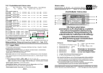
The principle of connection
(cell arrangement as the storeys in
a high-rise building)
p= orange, white
+= red
- = brown, black
To the balancing connector of the battery
+ cell 5
+ cell 4
+ cell 3
+ cell 2
+ cell 1
- cell 1
(fifth storey)
etc.
(fourth storey) = - cell 5
(third storey)
= - cell 4
(second storey) = - cell 3
(first storey)
= - cell 2
(ground floor) = earth
Dear customer,
Congratulations on your choice of the LiPoDiMATIC or the LiFeDiMATIC. This product makes it much safer to use
Lithium batteries in your model.
Every one of your models which is powered by these expensive batteries really should carry a LiPoDiMATIC or a
LiFeDiMATIC; it is as essential a unit as the balancer you always use when charging the Lithium battery.
1 Method of working
The LiPo/LiFeDiMATIC monitors each individual cell of your flight battery, checking for low voltage.
The LiPo/LiFeDiMATIC throttles back the motor well before any cell reaches the deep-discharged state - far less of
the reversal of the polarity. This causes the battery voltage to rise again slightly, thereby avoiding the danger of
deep-discharged cells.
If battery voltage continues to fall, the unit finally cuts the motor to avoid a deep-discharge situation.
2 LED indicator
When you initially connect the LiPo/LiFeDiMATIC to the flight battery, the integral LED flashes to indicate the flight
pack’s cell count; this continues for a short period (one minute).
If the unit detects low cell voltage during flight operations, the integral LED flashes to indicate the number of the cell
in the pack whose voltage was (or is) low.
This indicator goes out one minute after the LiPo/LiFeDiMATIC receives its last signal from the receiver (receiving
system switched off). The indicator can be re-activated by switching the receiving system on again.
If the balancing cable is connected wrongly to the LiPo/LiFeDiMATIC then the LED blinks quickly without pause.
3 Installation at the battery end
The LiPo/LiFeDiMATIC is connected to the balancer lead attached to the flight battery. The LiPo/LiFeDiMATIC
version should be chosen to match the balancer connector:
• LiPoDiMATIC-SE4
when the battery is equipped with a Schulze Elektronik BalCab10 socket.
• LiPo/LiFeDiMATIC-SE7 or -SE14 when the battery is equipped with a Schulze Elektronik BalCab20 socket.
• LiPoDiMATIC-TPxx
when a ThunderPower or FlightPower battery is used.
• LiPo/LiFeDiMATIC-KOxx
when the battery is equipped with a Kokam (Graupner, Robbe) socket.
A lot of any other connectors with a pin spacing of 2.54 mm can also be used - although it may be necessary to
re-connect the wires to obtain the correct sequence, or to “fill” vacant contacts.
4 Installation at the receiver end
The “servo lead” attached to the LiPo/LiFeDiMATIC should be connected to the throttle channel socket at the
receiver.
The “servo lead” attached to the speed controller or governor should be connected to the right-angled 3-pin socket
on the unit.
Note: the lead must be connected with the negative wires (brown or black) of the two cables facing each other.
If several batteries (several individual packs wired in series, or parallel-wired packs) are to be monitored by LiPo/
LiFeDiMATIC units, then the units must be wired together in series: the servo lead attached to the LiPo/LiFeDiMATIC is connected to the right-angled three-pin socket on the other LiPo/LiFeDiMATIC, instead of to the
receiver (See wiring example 3).
5 Speed controller / governor with BEC or opto-coupler
The LiPo/LiFeDiMATIC works correctly with both types of speed controller (opto-coupler or BEC) without any modification.
The conductor cross-section of the “servo lead” attached to the types for low cell counts are destined for BEC mode
operations (higher cross section). The “servo lead” of the types of higher cell counts is thinner (and therefore
lighter) for the use with an opto-coupler imnput stage which are used for reasons of safety.
The right-angled three-pin socket is another very deliberate feature, as the pins of most “servo leads” usually consist
of nothing more than sheet metal contacts, which cannot cope with heavy currents.
Operating Instructions
LiPo/LiFeDiMATIC Operating Instructions
2e
Requirements (Hint: As a rule in Futaba transmitters the throttle channel has to be switched to “servo reverse”)
The LiPo/LiFeDiMATIC can only work if your speed controller works with a shorter pulse signal (from the receiver or
transmitter) at “motor stopped” or “brake on” than at “full-throttle”. If this is not the case, the unit would apply full-throttle to
the motor as the battery became flat, instead of reducing motor speed and thereby reducing current drain.
The 3-pin connector type is deliberated used, because the normal plugs in a servo connector are normally made
from bended sheet matal which have a higher resistance than a massive plug.
7
Adjustments / Matching
The LiPo/LiFeDiMATIC can be configured to react to low cell voltage in different ways, making it suitable for
various types of application.
It is possible to select the voltage limits to provide for different residual motor run times. You can also set up the unit
so that the motor generates a “battery almost flat” signal to alert the pilot.
7.1 Voltage limit value LiPo (LiFe) and belonging solder pad confifgurations Pad 1 und Pad 2
The voltage limit values are dictated by the state of the solder pads 1 and 2:
• Throttle reduction at 2,5 (2,0) V Pad 1 soldered, Pad 2 open = pure cell protection function.
When the unit reduces the throttle, the battery is flat, i.e. no motor run time remaining.
• Throttle reduction at 2,8 (2,2) V Pad 1 open, Pad 2 soldered = Selection for saving some
final run time. Setting for cells which are operated at the limit of their maximum load capacity.
• Throttle reduction at 3,1 (2,4) V Pad 1 open, Pad 2 open =
(default state)
This setting provides an energy reserve of about one airfield circuit at reduced throttle.
1 2 3
1 = soldered
2,3= open
• Throttle reduction at 3,3 (2,6) V Pad 1 soldered, Pad 2 soldered = Setting for cells which
are discharged at low currents compared to the maximum permissible load.
7.2 Throttle reduction behaviour / Solder pad configurations
Heat shrinking tube
cut open and
7.2.1 Linear throttle reduction when the voltage of the most deeply discharged
lid high
cell falls to the set limit. The motor is continuously throttled back until it stops.
Recommended applications: gliders, helicopters.
Configuration:
pad 3 = open
1 2 3
all soldered
7.2.2 Staged throttle reduction when the voltage of the most deeply discharged cell falls to the
set limit. When a cell first falls to the low voltage limit, the unit forces a distinct reduction in
throttle, with the aim of warning the pilot that the battery will soon be flat, and that he should initiate the landing.
Thereafter the unit permits a maximum throttle setting of around 85% of the value which has been used up to
now. This causes the battery voltage to rise again slightly.
If the voltage again falls below the low voltage limit, the unit reduces the throttle setting again.
Recommended application: fixed-wing sports model aircraft, boats
Configuration:
pad 3 = soldered
8
Special notes
• Disconnect the controller / governor from the Lithium flight battery when not in use (to avoid deep-discharging).
• The LiPo/LiFeDiMATIC should not be left connected to the battery for days on end, as the voltage divider
(used to measure the cell voltages) will slowly discharge and unbalance the pack.
•The LED display function is reset when the LiPo/LiFeDiMATIC is disconnected from the Lithium battery.
9
Specifications
Ordering Information
Cells
LiPoDiMATIC-SE4
2 - 4 LiPo
LiPoDiMATIC-SE7
2 - 7 LiPo
LiPoDiMATIC-SE14
2-14 LiPo
Connector type
Schulze BalCab10
Schulze BalCab20
Schulze BalCab20
Weight about Servo cable
16 g 3*0,34 mm2
17 g 3*0,14 mm2
21 g 3*0,14 mm2
Current draw
0,12 - 1,2 mA
0,12 - 1,5 mA
1 - 3 mA
2 - 6 LiPo 7 pins univ., spacing 2.54mm 15 g 3*0,34 mm2
2*2-4 LiPo 2*5 pins univ., spacing 2.54mm 17 g 3*0,34 mm2
0,12 - 1,5 mA
0,12 - 1,5 mA
LiPoDiMATIC-TP5
4, 5 LiPo ThunderPower/FlightPower
LiPoDiMATIC-TP8 2,3,6,7,8 LiPo ThunderPower/FlightPower
LiPoDiMATIC-TP14
2-14 LiPo ThunderPower/FlightPower
16 g 3*0,34 mm2
17 g 3*0,34 mm2
21 g 3*0,14 mm2
0,12 - 1,5 mA
0,12 - 1,5 mA
1 - 3 mA
LiFeDiMATIC-Ko8
LiFeDiMATIC-SE7
LiFeDiMATIC-SE14
16 g 3*0,34 mm2
17 g 3*0,14 mm2
21 g 3*0,14 mm2
0,12 - 1,5 mA
0,12 - 1,5 mA
1 - 3 mA
LiPoDiMATIC-Ko6
LiPoDiMATIC-Ko2x4
3 - 8 LiFe 9 pins univ., spacing 2.54mm
3 - 7 LiFe Schulze BalCab20
3-14 LiFe Schulze BalCab20
Schulze Elektronik GmbH • Prenzlauer Weg 6 • 64331 Weiterstadt • Fon: +49-6150-1306-5, Fax: 1306-99
www.schulze-elektronik-gmbh.com
[email protected]
• Germany •
Seite
3
Stand 01.09
Operating Instructions
LiPo/LiFeDiMATIC Operating Instructions
LiPo/LiFeDiMATIC Bedienungsanleitung
Issue 01.09, Page
rechts / right
Gas-Kanal
Throttle-channel
LiPoDiMATIC-SE14 mit BalCab20 Stecker
für 5s - 14s Packs
3
Drehzahlsteller mit BEC, nicht LiPo-fähig
LiPoDiMATIC-SE14 w. BalCab20 plug
for 5s - 14s packs
Speed controller with BEC, not for LiPo batteries
Ohne Abb. / No picture
LiPoDiMATIC-SE7 mit BalCab20 Stecker
für 2s - 7s Packs
LiPoDiMATIC-SE7 w. BalCab20 plug
for 2s - 7s packs
Balanceranschluß
Balancing connector
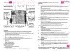
Verdrahtungsbeispiel 1 / Typical wiring arrangement 1
Zum Steller / To the controller
Drehzahlsteller/-regler mit Optokoppler / Speed controller with opto-coupler
Impuls / pulse (signal)
Plus / pos.
Minus / neg.
Zusatzkondensatoren wegen langer Powerkabellänge
Additional capacitors required for long power cables
Zum Empfänger
To the receiver
2 * 26 cm interne Kabellänge im Akkupack!
2 * 26 cm (2 * 10“) internal „power cable“ length of the
battery
unten / below
LiPoDiMATIC-Ko6 mit Universal-Stecker für 2s-6s Packs
LiPoDiMATIC-Ko6 with universal plug for 2s - 6s packs
Achtung: Die Anschlussbuchsen (weiblich) des BalancerKabels müssen evtl. umbelegt werden um die HochhausKonfiguration (Seite 1 rechts oben) zu erhalten.
Caution: It may be necessary to re-arrange the female sockets of the balancer cable in order to obtain the cell arrangement as shown at the top of page 1 („high rise building“).
= schwarz = Pin1 = „-“ Zelle 1 = „-“ Akku
= black = Pin1 = neg. cell 1 = neg. battery
LiPoDiMATIC-SE14
1 2 3
offen / open
Löt-Pads im Auslieferzustand
Solder pads at delivery state
Verdrahtungsbeispiel 2 / Typical wiring arrangement 2
LiPoDiMATIC-SE4 mit BalCab10
Stecker
für 2s - 4s Packs
4s-Pack
Empfänger / Receiver
4s-Pack
Empfänger-Akku
Receiver battery
Empfänger
Receiver
2 frei not used
2s-Pack
Zwei / two
LiPoDiMATIC
seriell verschaltet
wired in series
4 frei / not used
3s-Pack
Umgesteckt / re-arranged
3 (!) frei
/ not used
5s-Pack
1 Pin frei
1 pin not used
LiPoDiMATIC-SE4 with BalCab10plug for 2s - 4s packs
Zwei Packs à 4s = 8s
Two packs of 4s = 8s
Steller-/
Regler
Speed
controller
Verdrahtungsbeispiel 3 / Typical wiring arrangement 3