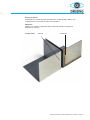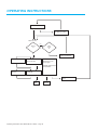
1
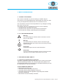
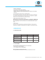
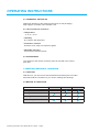
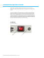
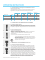
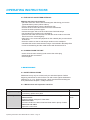
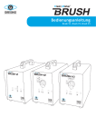
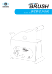
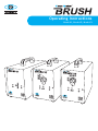
Operating Instructions
Brush V1, Brush V2, Brush V3
3
2
1
-1-
operating instructions
PRODUCT DESCRIPTION
Model:
Unit No.:
Built:
CUSTOMER REGISTRATION
Registration No.:
The user is obliged to:
· observation of EC Directive 89/655 and its
national implementation
· observation of the current national regulations concerning industrial safety
· utilisation of the machine in accordance with the
instructions
All rights reserved.
Printing, in whole or in part, is only allowed
with prior consent of the manufacturer.
Kai Greising e. K.
Clean Marker
www.greising.com
[email protected]
Industriestraße 29/2
D-73340 Amstetten
Tel. +49 (0)73 31/30 58 - 0
Fax +49 (0)73 31/98 17 22
ORDER PROCESSING + 49(0)73 31/30 58 - 20
ORDERING STENCILS
+ 49(0)73 31/30 58 - 22
Operating Instructions Clean Marker Brush V-Series − Page 2
INDEX
1SAFETY REGULATIONS
5
1.1 Correct utilisation
1.2 Tips and definitions
1.3 Obligations and liability
5
5
5
2INTRODUCTION
7
2.1 Technical data 2.2 Conformity 2.3 Transport, storage
2.4 Accessories 7
7
8
8
3 FUNCTION, METHOD OF OPERATION
8
3.1
3.2
3.3
3.4
Function review
Method of operation
Safety and monitoring equipment
Operating and display elements
3.4.1 Front side, front display
3.4.2 Back side
8
9
9
9
9
10
4 TRANSPORT, STARt-UP
11
4.1
11
11
11
11
Safety regulations
4.1.1 Temporary storage
4.1.2 Set-up
4.1.3 Start-up
5operation
11
5.1 Start-up
5.1.1 Instrument setting
5.2 Cleaning with the Clean Marker Cleaner (60° tool)
5.2.1 Tips for optimal cleaning
5.2.2 Cleaning process
5.3 Marking with the Clean Marker Cleaner (flat tool)
5.3.1 Tips for optimal marking
5.3.2 Marking process
5.4 The use of short-term stencils
5.5 Switching off the device
11
12
12
12
12
12
12
13
14
14
Operating Instructions Clean Marker Brush V-Series − Page 3
operating instructions
6MAINTENANCE
14
6.1 Safety regulations
6.2 Maintenance and inspection check list
14
15
7MALFUNCTIONS
15
7.1 Safety regulations
15
8 DECOMMISSIONING, Storage
15
8.1 Preparation for storage
8.2 Package, transport
8.3 Maintenance during storage
15
15
16
9DISPOSAL
16
9.1 Procedure
16
10YOUR OPINION
18
Operating Instructions Clean Marker Brush V-Series − Page 4
1 SAFETY REGULATIONS
1.1 CORRECT UTILISATION
The units are intended only for the marking of metallic objects.
The function is only guaranteed when original parts are used. Any other
or any use beyond those determined is not considered correct.
The manufacture cannot be held responsible for any damages resulting
from such incorrect use.
The following are also considered to be part of correct utilisation:
• Compliance with operating instructions.
• Compliance with inspection and maintenance requirements.
• Use of protective clothing, especially gloves and goggles.
1.21.2TIPS AND DEFINITIONS
Warning
A possibly dangerous situation which could lead to serious
injury or even death.
Warning
A possibly dangerous situation, which could lead to light
physical injury. This sign is also used as a warning for heavy
material damage.
Information
Concerning usage and other useful information.
Information
The arrow describes a following process occurring automatically and / or the condition which should now be set.
1.3 Obligations and liability
1.3.1 Necessary qualifications of operators
Operation, maintenance and inspection may only be carried out by authorised and qualified specialists. The minimum age of the operator is 18.
Authorised specialists are understood to be specialists trained by the user,
the manufacturer or the service partner.
These operators must be:
• trained in the use of the unit
• conversant with the operating instructions
• conversant with the safety equipment of the unit
• conversant with the relevant regulations (especially with accident
prevention regulations)
• authorised to use the necessary chemicals
Operating Instructions Clean Marker Brush V-Series − Page 5
operating instructions
1.3.2 Risks involved when using the unit
The unit has been built in accordance with the latest technical standards
and the recognized regulations concerning safety. In spite of this, danger of
injury to the user or a third party and/or damage to the unit or other materials could arise during use. The unit may only be used:
• for the process previously determined
• in a perfectly safe condition
1.3.3 Guarantee and liability
Our „General Conditions of Sale and Supply“ are applicable. Claims of
warranty and liability made for personal injuries and material damages are
excluded if they result from one or more of the following causes:
• incorrect use of the unit
• non - observance of operating instructions
• unauthorised structural changes on the unit
1.3.4 Safety measures
The instructions for use are to be kept near the unit and are to be passed
on by sale or exchange of the machine.
All safety and danger signs on the unit are to be clearly visible at all times.
1.3.5 Risks arising from electrical energy
• Work on the power supply is only to be carried out by the same
electrician.
• The electrical equipment is to be checked regularly.
• Loose connections and damaged cables must be remedied immediately
1.3.6 Special risks arising from chemicals
Dealing with chemicals should be considered a special risk. Pay attention
to the Safety Data Sheets and the following remarks in these instructions:
Eye protection
Eyes should be protected from chemicals with goggles
Hand protection
Put on rubber gloves before working with chemicals
Clothes protection
Wear protective clothing before using chemicals (acid - proof apron,
working coat)
Breathing protection
Fumes arise when using chemicals. Always wear a face mask!
Accident with chemicals
Should chemicals come into contact with eyes in spite of wearing
goggles, then:
• rinse the eyes with plenty of clear water
• seek medical attention.
Operating Instructions Clean Marker Brush V-Series − Page 6
• further information
- Do not eat or drink at the workplace.
- Always wash your hands before taking a break.
- Keep the equipment and chemicals away from children and unskilled
personal.
1.3.7 Maintenance and servicing, repairing faults
The prescribed maintenance work and inspections are to be carried out
on schedule. Before beginning maintenance work, inspection or repairs,
switch the unit off and secure by „pulling the plug“.
1.3.8 Constructional changes on unit
Without the prior consent of the manufacturer, no alterations, additions or
removals of any sort may be made on the unit. Only spare or replacement
parts originating from the manufacturer or his authorised dealer may be
used.
1.3.9 Emission
Electrolyte may vaporise during etching and cleaning. These vapours
should not be inhaled. Provide fresh air circulation in your place of work.
2 INTRODUCTION
2.1 TECHNICAL DATA
general data
Brush-V1
Brush-V2
Brush-V3
dimensions
W x H x D [mm]
145 x 250 x 330 145 x 250 x 330 145 x 250 x 330
weight, approx. [kg]
8,0
8,0
8,3
service output
380 VA
380 VA,
380 VA
2.2 CONFORMITY
The unit fulfils the following regulations and standards:
• EMV Directive 2004/108/EG
• Low Voltage Directive 2006/95/EG
The CE - label is on the front of the unit.
The type plate with the special unit number is attached to the rear.
Operating Instructions Clean Marker Brush V-Series − Page 7
operating instructions
2.3 Transport, Setting up
Please pay attention to the transport instructions on the packaging.
Keep upright. If possible, store vibration - free.
2.3.1 Environmental conditions
• Temperature
- 5 °C to + 55 °C
• Humidity
dry, indoors, dew-protected
• Installation location
dust-free, level, away from explosive gases
• Workable materials
all conductive metal surfaces
2.4ACCESSORIES
The contents of the various accessory sets can be read in the current
price-lists.
3 Function, Method of Operation
3.1FUNCTION
With this unit, you can remove discolourations and oxide layers from stainless steel surfaces. Furthermore, you can do markings and etchings.
3.2 METHOD OF OPERATION
Brush-V1
pickling with electrode
pickling with brush
polishing with electrode
dark markings with tool
Operating Instructions Clean Marker Brush V-Series − Page 8
Brush-V2
Brush-V3
Electrochemical pickling, marking and etching.
3.3 SAFETY AND MONITORING EQUIPMENT
• 35 Amp (4) overload safety switch on the front of the unit
• 4 Amp (7) cut-out on the rear of the unit
3.4 OPERATING AND DISPLAY ELEMENTS
3.4.1 Front side, front display
(1)
Red connecting socket for the working piece (earth cable)
(2)Black connecting socket for the tool and brush attachments
(3)
Selector switch
(4) Cutout 35 Amp
(5)
Green indicator light, showing state of operation
1
2
3
4
5
Operating Instructions Clean Marker Brush V-Series − Page 9
operating instructions
When electro - polishing, material is removed from the surface of the
workpiece by specific electrolytes used in conjunction with an external DC
source.
The material set free by the electrolyte is non - polluting and follows under
flattening conditions. In contrast to mechanical removal processes, flattening by electro - polishing begins in the micro range and includes, during
longer polishing periods, larger structures which are rounded and flattened
off on their top surface. During electro - polishing, two different mechanisms
work simultaneously, one flattens the upper surface in the micro range and
the other achieves fine deburring in the macro range.
3.5.2 Reverse
(6) Main switch
(7) Cut-out 4 Amp
6
Operating Instructions Clean Marker Brush V-Series − Page 10
7
4 Transport, START-UP
4.1 SAFETY REGULATIONS
4.1.1 Temporary storage
Always keep the unit in its outer packaging and in a dry room indoors.
4.1.2 Set-up
Without using sharp tools, remove the outer packaging carefully.
Keep the original packaging. Always use it for storing and transporting the
unit.
4.1.3 Start-up
• check that the mains voltage is the same as that on the type label and is
the same as the setting
• using the mains cable connect the unit to the mains voltage; push the red
cable into the red connecting socket (1)
• fix the earth clamp to the red cable and then on the workpiece
• push the black cable into the black connecting socket (2)
• fix the other end of the cable into the tool for marking and polishing or the
brush for cleaning
• switch on the unit at the main switch (6), the green light (5) should be lit,
the unit is ready
• set the unit as desired (only on V2 and V3)
5 OPERATION
5.1 START-UP
Carry out a check and inspection, not only prior to initial operation, but also
prior to every set up. Set up the unit as described above.
Working with chemicals can be dangerous. Always wear a face mask,
acid-proof apron, goggles and gloves. When using Greinox 1000 / 2000 / Polish, Rapid please read the Safety Data Sheets first (currently to be
found under www.greising.com / Clean Marker /Service).
Do not inhale the vapours arising. Should there be skin contact, wash with
plenty of water.
Operating Instructions Clean Marker Brush V-Series − Page 11
operating instructions
5.1.1 Unit adjustments for cleaning for Clean Marker Brush devices
selector switch (see page 9).
Clean Marker Brush V1 units do not have a selector switch and are only
applicable for pickling with brush and dark markings with electrode.
brush attachm. 1 (A)
selector switch
brush attachm. 2 (B)
etching tool (C)
+ etching felt 1
cleaning tool
60° (D) + polishing felt
symbol
1 pickling with brush
2
pickling with electrode
3 polishing
4 dark marking
5.2Cleaning with Clean Marker brush attachments
5.2.1 Tips for optimal cleaning
With the Clean Marker brush attachment you can clean even inaccessible
parts. The short brush shows more powerfull performance, the long brush
is especially for big areas. Change the brush in time to avoid short circuits.
A
b
5.2.2 The „Cleaning“ Process
• screw on the brush attachment
• adjust the unit according to Chapter 5.1.1
• fill about 1 cm Greinox 1000, 2000, Polish or Rapid into the wide-neck
container; more can be filled into the containers for pump units
• moisten the tool
• run the tool over the oxide layer until the surface is clean
To avoid white edges on the work piece: polish the cleaned
work piece with the cleaning cloth supplied, lightly moistened
with water and Neutralyt.
Croping the brush will increase performance. However, this
may lead to short circuit signs.
5.3MARKING with the Clean Marker (flat tool)
c
d
5.3.1 Tips for maximum marking effect
Every electrolyte contains salts. Depending on the material, these salts
can have a strongly oxidizing effect. Extreme cleanliness must be used
when handling the chemicals. Avoid carry - over of electrolytes and wash
your hands frequently. Make sure of good power contact and moist felt.
Felt which is too dry restricts the flow of power. Stencils become clogged
with salts and metals after a while. They should also be rinsed and cleaned
frequently. Electrolyte can also be used for cleaning stencils. Small
surfaces can best be marked by simply pressing the felt on the stencil.
Larger areas are best marked by stroking the tool head several times over
the entire surface of the stencil. This takes between 1.5 and 2 seconds. If
the marking appears rusty, then either do not use the tool quite so long or
decrease the voltage. The tool should be held at right angles to the
work piece and the whole surface used for contact with the stencil.
Operating Instructions Clean Marker Brush V-Series − Page 12
Move slightly back and forth.
the electrolyte flows better through the stencil
Do not allow the stencil to become too warm as this could lead to premature wear and tear. When electrolyte vaporises it leaves residues in the
stencil tissue. In time this reduces the clarity of the marking. Dark, i. e. dirty,
felts must be changed frequently and the larger the stencil, the quicker the
felt needs changing.
The results of lettering depend on various factors. The results can vary
depending on material or within a material batch. Test the lettering for
quality on a piece of waste material before beginning to work. The lettering
can usually be optimised by using various parameters and electrolytes. By
using switch (4) you can set whether the lettering should be dark or light.
The result differs with different materials.
More material is removed with light lettering. The stencil gets dirty very
quickly and must be cleaned more often. Light letterings are often used with
stainless steel. However, the result is not predictable because each aluminium has a different oxide layer.
5.3.2 The „Etching (marking)“ Process
• clean the spot to be etched
• cut off 30 mm etching felt (t = 2 mm) from the 60 x 2 x 1000 strip or from
the sheet
• using the „O“- ring, fix the felt pad to the tool head
• using the selector switch (4) set the unit to the desired setting for light
or dark etching
• add enough electrolyte to the felt on the underside of the tool so that it
is wet
• position the stencil in the desired position on the work piece
• using light pressure and small swivelling movements stroke over the
stencil or, if the stencil is small enough to be covered by the tool head,
then simply press down and move slightly to and fro, holding the tool
at right handles to the work piece
• 1.5 to 2 seconds should be long enough to produce a good etching
although this depends on the material and the size of the stencil
• remove electrolyte from the metal surface and the lettering
• neutralize the surface with a cloth soaked in Neutralyt GN 2 several times
• then finally conserve the surface and the etching with Konservat GK 2
There is a special tool head for etchings wider than 30 mm.
Operating Instructions Clean Marker Brush V-Series − Page 13
operating instructions
5.4 The use of short-term stencils
Marking with short - term stencils
• place the short-term stencil with the blue/green side facing you into the
typewriter/matrix printer (without ribbon)
• type the desired lettering onto the blue/green side
• remove the short-term stencil and cut it to the desired size
• remove the white protective paper
• moisten the upper side of the short-term stencil with electrolyte
• put the stencil into position on the workpiece
• press the tool head onto the stencil so that the whole surface covers the
stencil and move it around gently
• after about 1.5 to 2 seconds (depends on the material) the process should
be finished
• clean the surface so that no electrolyte remains on the workpiece
• neutralize the surface several times using a cloth soaked in Neutralyt GN 2
• conserve the lettering and the metal surface with Konservat GK 2
5.5 CLOSING DOWN THE UNIT
• switch off at the main switch (6) and remove the mains plug
• dismantle all the accessories
• clean all parts
6 MAINTENANCE
6.1 SAFETY REGULATIONS
Maintenance may only be carried out by an authorised person. Before
beginning maintenance, switch off the unit and secure against inadvertent
switching on, e. g. by „pulling the plug“. Work must be executed along the
lines prescribed in Chapter 1 „safety measures“ .
6.1.1 Maintenance and inspection check list
intervals
control position / advice of maintenance
daily, before using
Check the device and the stencil/brush.
If necessary replace worn parts.
after using
Clean stencils, tool head, cable and stainless steel working surface.
Clean stencils:
carefully between 2 fingers in clear water.
Clean tool head:
unscrew handle from carbon head and clean both in plenty of water.
Clean unit and cable:
wipe with a moist cloth.
Operating Instructions Clean Marker Brush V-Series − Page 14
utilities
a soft cloth,
brush
6.2
GENERAL REMARKS
Do not use cleaning agents, metal objects or compressed air. Dust and
glue residues must be removed with a scraper made of plastic.
Dismantle and clean the tool after use. If not, acid could
concentrate to such a degree that it becomes a health hazard.
The supply of power through the cable could also be affected
and the performance reduced.
7MALFUNCTIONS
7.1 SAFETY REGULATIONS
Repairs may only be carried out by an authorised person. Before beginning
repair, switch off the unit and secure against inadvertent switching on, e. g.
by „pulling the plug“. Work must be executed along the lines prescribed in
Chapter 1 „safety measures“ .
malfunction
cause
corrective
short-circuit
• Fibre glass is worn and must be
replaced.
Replace fibre glass and press
overload safety switch again after
a short waiting period.
• The 4,0 Ampere main fuse possibly
melted.
performance too low or no
performance
• cleaning tool not cleaned
• contact problem
• oxidated plug
If current is too high, the 4,0
Ampere main fuse might have
melted.
Change cable, replace clamp,
dismantle and clean plug
8 DECOMMISSIONING, Storage
The unit must be stored in the environment described in Chapter 4.1.
8.1 PREPARATION FOR Storage
Clean the unit and accessories and make sure that all the equipment is
carefully packed and the chemical containers are closed firmly.
8.2 PACKING, TRANSPORT
Always store the original packaging. Use it for storing and for transport.
Operating Instructions Clean Marker Brush V-Series − Page 15
operating instructions
8.3 MAINTENANCE DURING STORAGE
There is no maintenance to be carried out during storage.
Electrolyte, Neutralyt and Konservat should be kept in a cool and dark
place, protected from direct sunlight.
9DISPOSAL
Disposal of old Electrical & Electronic Equipment
(applicable throughout the European Union and other
European Countries with separate collection programmes).
This symbol, found on your product or on its packaging, indicates that
this product should not be treated as household waste when you wish to
dispose of it. Instead, it should be handed over to an applicable collection
point for the recycling of electrical and electronic equipment. By ensuring
this product is disposed of correctly, you will help prevent potential negative
consequences to the environment and human health, which could otherwise be caused by inappropriate disposal of this product. The recycling
of materials will help to conserve natural resources. For more detailed
information about the recycling of this product, please contact your local
city office, household waste disposal service or the retail store where you
purchased this product.
9.1 PROCEDURE
• Use Neutralyt GN 2 to neutralize Greinox waste to pH 7.
• Used fibreglass pads, cloths and fluid remains should be neutralised to
pH 7 with Neutralyt GN 2.
• The soiled water can then be disposed off in the normal way.
• Fibreglass and cloths contain metal components and should be disposed
of as if metal waste.
Operating Instructions Clean Marker Brush V-Series − Page 16
Electronic waste.
Dismantle into component parts (transformers, mother boards, cables, etc.)
and dispose of in accordance with local regulations.
Materials:
Metals, non - metals, composites and accessories should be sorted and
disposed of correctly.
welded seam
cleaned uncleaned
Operating Instructions Clean Marker Brush V-Series − Page 17
operating instructions
cable in outlet
yes
no
put cable into outlet
switch on unit
no
light is
lit
light
is not
lit
ja
connect cable and tool
red and black cable,
tool connected
no
clean tool
check cut out 4 A,
replace if necessary
yes
Unit is overheated.
Wait approx. 6 min.
and try again.
Overload safety switch
16 A activated.
unit works
no
yes
no
yes
push overcurrent
cutout
OK
Operating Instructions Clean Marker Brush V-Series − Page 18
Service
10 WE ARE INTERESTED IN YOUR OPINION
We constantly strive for an improvement in quality and would be interested
to have your opinion concerning our products and operating instructions.
Please use this fax form.
Customer:
Unit type:
Order no. :
Please call us back on number:
Remarks, suggestions:
Date:Name:
Operating Instructions Clean Marker Brush V-Series − Page 19
12 DECLARATION OF CONFORMITY
According to Low Voltage Directive 2006/95/EG
Manufacturer: Kai Greising e. K.
Clean Marker
Industriestr. 29/2
D-73340 Amstetten
Tel. 07331 / 30 58-0
Fax 07331 / 98 17 22
Description of components:
Electrochemical pickling and etching units
The CE - sign was attached for the first time 2013
Type:
Clean Marker V Brush
We hereby certify, as manufacturer, the conformity of the mentioned components
with the European standards, especially with the product standards of the
DIN EN 61558 (VDE 0570) standards and the conformity with the Low Voltage
Regulations 2006/95/EG.
The safety directions included in the product documentation are to be observed.
Siegfried Maier
Production ManagerAmstetten 02.03.2013