1
Installation and operating instructions
KEMPER KHS Mini System Control
KEMPER KHS Mini System Control MASTER
KHS Mini System Control SLAVE
Figure 686 02 005
Figure 686 02 006
TABLE OF CONTENTS
1.
GENERAL INSTRUCTIONS: ................................................................................................................ 1
2.
AREA OF APPLICATION .................................................................................................................... 2
2.1
Operating modes for the water exchange ....................................................................... 2
2.2
KHS MASTER/SLAVE technology ....................................................................................... 2
2.3
Water exchange groups ..................................................................................................... 2
3.
SAFETY ............................................................................................................................................. 3
3.1
Safety Instructions .............................................................................................................. 3
3.2
Hazards if the safety instructions are not complied with ............................................... 3
3.3
Unauthorized alteration and spare part fabrication ....................................................... 3
3.4
Unauthorised modes of operation .................................................................................... 3
4.
TECHNICAL DATA ............................................................................................................................ 4
5.
CAN BUS SYSTEM OVERVIEW .......................................................................................................... 5
5.1
Layout variants ................................................................................................................... 5
5.2
Terminal resistance ............................................................................................................ 6
5.3
Connection of terminal resistor ........................................................................................ 6
6.
ASSEMBLY........................................................................................................................................ 7
6.1.
Wall mounting.................................................................................................................... 7
6.2
Electrical installation KHS Mini System Control ............................................................... 8
6.2.1Terminal description -MASTER- and -SLAVE- ..................................................................................... 8
6.2.2Detailed illustration of the terminals for cable entry ...................................................................... 9
6.2.2.1Power supply connection .................................................................................................................... 9
6.2.2.2Connection of KHS Isolating valve with servo-drive (Figure 686 00) ................................................... 9
6.2.2.3Connection of KHS Isolating valve with spring reset servo-drive (Figure 686 01)................... 10
6.2.2.4CAN bus connection ........................................................................................................................... 10
6.2.2.5Connection of external switch ......................................................................................................... 11
6.2.2.6Connection of KHS-CONTROL-PLUS flow measurement valve (Figure 638 4G) ....................... 12
6.2.2.7Connection of KHS Temperature sensor Pt 1000 (Figure 628 0G) .............................................. 13
6.2.2.8Connection of KHS drain with overflow monitor (Figure 688 00) ............................................. 13
6.2.2.9Connection of water sensor (Figure 620 00) ................................................................................... 14
6.2.2.10Connection of floating alarm relay .............................................................................................. 14
7.
COMMISSIONING ................................................................................................................... 15
Manual KHS Mini System Control MASTER
8.
CONFIGURATION ................................................................................................................... 16
8.1.1
Basic menu operation and functions ........................................................................................ 17
8.1.2
General plan ................................................................................................................................... 18
8.1.4
Main menu ..................................................................................................................................... 20
8.1.4.1
System settings .............................................................................................................................. 21
8.1.4.2
CAN BUS setup .............................................................................................................................. 24
8.1.4.3
Device settings .............................................................................................................................. 25
8.1.4.4
Operating modes ......................................................................................................................... 28
8.1.4.5
Journal ............................................................................................................................................ 33
8.1.4.6
Switching programs ..................................................................................................................... 34
8.1.4.7
Valve manual mode ..................................................................................................................... 35
8.1.4.8
Error handling ............................................................................................................................... 36
8.1.5
Using the USB interface .............................................................................................................. 37
8.2
Configuration PC-software ............................................................................................... 38
9.
DESCRIPTION OF MALFUNCTIONS AND MALFUNCTION REPAIR .......................................... 39
10. DIMENSIONS, ATTACHMENT DIMENSIONS ........................................................................... 41
11. ACCESSORIES ......................................................................................................................... 42
12. WIRING INSTRUCTIONS FOR COMPONENTS WITH ELECTRICAL CONNECTION ..................... 42
13. APPENDIX .............................................................................................................................. 43
13.1
Valve technology .............................................................................................................. 43
13.2
Overview for the system commissioning of the KHS Mini System Control .................. 43
Manual KHS Mini System Control MASTER
1.
General instructions:
Assemble and commission the KEMPER KTS Mini System Control only after reading these
assembly and operating instructions. It informs you in detail about the assembly,
commissioning, operating principles and operation of the Kemper KHS Mini System
Control. If you cannot find the information and instructions you need in these operating
instructions, ask the manufacturer, Gebr. Kemper (please refer to last page for the
address). Keep the mounting and operating instructions with the device or file it with the
other technical documentation in the system documentation.
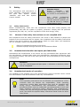
Symbols used
The symbols used in the text are explained below.
List of symbols
Note:
Useful information
Warning notice:
Danger electric shock
Attention:
Imminent danger
Maintenance:
Maintenance/Repair
Manual KHS Mini System Control MASTER
1
2.
Area of application
The KEMPER KHS Mini System Control can be used for monitoring and water exchange in
drinking water systems. The water exchanges can be generated and documented as
flushing logs with the -MASTER- control. The dedicated water exchanges prevent
stagnation in the drinking water with the aim of maintaining the drinking water hygiene
in the drinking water systems. The KHS Mini System Control -MASTER- can be
parameterised by a PC-software or by the internal menu.
NOTICE:
If two or more valves are simultaneously opened in a drinking water
system, under certain circumstances pressure fluctuations or a large
pressure drop can occur in the system. For that reason, make sure
beforehand that the required flow pressure is continuously guaranteed
at all tapping points. It is recommended to not make simultaneous
water exchanges.
Operating modes for the water exchange
2.1
Time controlled water exchange
Temperature controlled water exchange
Volume controlled water exchange
2.2
KHS MASTER/SLAVE technology
The -MASTER/SLAVE- technology can be used to trigger flushing measures for
maintaining the drinking water hygiene for the drinking water system. The corresponding
operating modes can be individually configured for each individual water-exchange
group. Positioning the individual -MASTER- or -SLAVE- controls directly on the water
exchange groups ensures short wiring distances for interconnection.
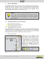
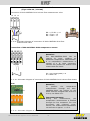
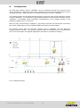
2.3
Water exchange groups
(2)
(1)
(3)
(4)
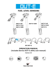
Shown in Ill. 2.1 as an example is a KHS
Mini System Control -SLAVE- (2) in
connection with a water exchange group
which comprises a KHS Isolating valve (4),
Temperature sensor (1), Volume flow sensor
(3) and a KHS Drain (5). The components of
the water exchange group are only listed as
examples here. The operating mode
depends on the components. In the example
illustrated, the -SLAVE-(2) controls the
specified water exchange groups. It is
connected with the -MASTER- through a
CAN bus cable.
Note:
Maintenance cut-offs are
commended in front of
Volume flow sensor (3).
(5)
Ill. 2.1 Illustration of a water exchange
group
Manual KHS Mini System Control MASTER
2
rethe
3.
Safety
Warning notice:
During
assembly
and
maintenance, make sure that
the control is not switched on.
The descriptions and instructions in
these operating instructions concern
the
KHS
Mini
System
Control
-MASTER- and KHS Mini System
Control -SLAVE-.
3.1
Only
skilled
professional
personnel are permitted to
operate electrical systems (as
per DIN EN 50110-1). Danger
of fatal electric shock.
Safety Instructions
Before commissioning, make sure the connections have been made properly and
professionally and that the system is properly protected. Comply with the pertinent
regulations (EN, VDE, etc.) and the regulations of the local energy utility.
3.2
Hazards if the safety instructions are not complied with
Non-compliance with the safety instructions can result in both hazards to people and
hazards to the environment and the system. Non-compliance with the safety instructions
leads to the loss of rights to any compensation claims. In some cases, non-compliance
can, for example, result in the following hazards:
Failure of important functions in the device
Hazards to people through electrical and mechanical effects
3.3
Unauthorized alteration and spare part fabrication
Alternations and modifications to the device are only permissible after agreement with
the manufacturer. Original spare parts and manufacturer authorised accessories serve
the purpose of safety. The use of any other parts may annul the liability for any resultant
consequences.
Attention:
Use only original/approved spare parts otherwise no warranty claims
will be recognized.
3.4
Unauthorised modes of operation
The reliability of the supplied unit is only ensured when used as intended. Never exceed
the limits stated in this documentation under any circumstances.
Note:
If the operating instructions are not followed, the manufacturer of this
controller does not assume any responsibility. These operating
instructions contain basic instructions that must be complied with
during set-up, commissioning and maintenance. Therefore, the
plumber/mechanic and the responsible specialists/operators must read
these operating instructions before assembly and commissioning.
Comply not only with the general safety instructions listed in this main
point; also follow the specific safety instructions listed under the other
main points.
Manual KHS Mini System Control MASTER
3
4.
Technical Data
Technical Data
Power supply 230 V AC 50/60Hz
Display Graphic display with background lighting
Operation with 4 buttons: Up | Down | Enter | Esc
Relay flush valve switching capacity 230 V, 2 A
Floating alarm relay, max. 230 V, 2 A
16 memory locations for the operating modes:
Time controlled water exchange
Temperature controlled water exchange
Volume controlled water exchange
Routine-time, routine-duration and routine-volume
For connecting:
1 ea. KHS Isolating valve-plus or KHS Isolating valve
1 ea. KHS Temperature sensor Pt 1000
1 ea. KHS Control Plus volume flow measurement valve
1 ea. KHS overflow monitor
Acoustic alarm signal in case of faults (disengageable)
Alarm acknowledgement on -MASTER System is expandable: 1 -MASTER- with max. 62 - SLAVEs- via CAN bus
Bus system connection per direction: CAN installation cable, max. 1000m
total length, overall 2000m possible
Serial interface for the PC-link by the customer for configuration and for
reading out the flush log
Can save 50,000 journal entries
External switch | Switchover:
Program 1 (e.g. school-holidays program)
Program 2 (e.g. school program)
Maintenance mode (system is blocked)
Menu driven operation in German, English or Dutch
Internal consumption 10 VA
Manual operation of the valves on device
Ambient temperature range from 0 °C to 50 °C
Protection class IP 54
Surface mounted housing for wall installation
USB interface for updating the firmware, reading out the journal and data
logging and for downloading and uploading the configuration file
Network link through network cable (accessory)
Manual KHS Mini System Control MASTER
4
5.
CAN bus system overview
The basic version of the -MASTER- control system includes as the smallest solution a
flushing valve for water exchanging measures. This -MASTER- System Control is
required for triggering the flushing valve and for signal evaluation.
Up to a maximum of 31 -SLAVE- controls per CAN-BUS connection of the -MASTERcan be controlled per CAN bus connection. Furthermore, the -MASTER- System
Control, using two integrated CAN bus connections, can trigger up to 62 -SLAVEcontrols and one directly-connected KHS water exchange group.
That means up to 63 KHS water exchange groups can be connected and operated.
The accumulated total length of one CAN bus connection can amount to a
maximum of 1000 m (total length is thus 2000m).
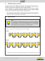
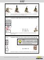
5.1
Layout variants
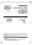
Note:
The controllers must be connected in series, as can be seen in Example
1. During this, the -MASTER- System Control can be connected within
the series (Variant 2) or as a final subscriber (Variant 1). Branches or
start connections, as can be seen in Example 2, are not possible.
Furthermore, shorter cable distances are recommended.
Example 1: Layout variant, KHS-Mini System Control -MASTERVariant 1
CAN bus
A
Variant 2
CAN bus
CAN bus
B
A
Ill. 5.1 Illustration of a layout variant, KHS Mini System Control -MASTER- system control
Manual KHS Mini System Control MASTER
5
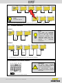
Example 2: Incorrect layout
CAN bus
A
Note:
Incorrect layout
Ill. 5.2 View of an impermissible layout variant, KHS Mini System Control -Master-
5.2
Terminal resistance
Variant 1
Note:
The
120
Ω
terminal
resistance must be installed
only in the last control
component (-SLAVE-) of a
CAN bus cable line. The
-MASTER- control does not
require
a
terminal
resistance.
CAN bus
A
Variant 2
CAN bus
CAN bus
B
A
Ill. 5.3 Illustration of a CAN bus line with terminal resistor
5.3 Connection of terminal resistor
Attention:
All
KHS
Mini
controls
-SLAVE- are supplied with a
120 Ω terminal resistor.
For non-terminal -SLAVEcontrols, the resistor must be
removed!
120 Ω
Ill. 5.4 Illustration of the terminal resistor
connection
Manual KHS Mini System Control MASTER
6
6.
Assembly
Warning notice:
Allow only certified electricians to assemble and install electrical
equipment. Danger of fatal electric shock.
Very strong magnetic fields can impair the functioning. Interferences can be prevented
by following the installation rules below:
Do not mount the controller and the sensors near inductive loads (motors,
transformers, contactors, etc.).
Feed through a separate mains voltage circuit (if necessary, with an a.c. mains
filter).
Inductive loads must be equipped with safeguards to reduce overvoltages
(varistors, RC-filter).
Attention:
When using the controller together with other devices in one system,
check to see if that causes interference signals to be emitted.
6.1.
Wall mounting
The KHS Mini System Control is intended for wall installation. The housing has 4 each ø
4mm mounting holes in a clearance of w = 188mm and h = 88mm. Additional
dimensions are listed in Chapter 10. To mount, open the cover and screw the device
tightly to the wall. After mounting the housing, make the required electrical connections.
Ill. 6.1 Illustration of the mounting holes for wall installation
Manual KHS Mini System Control MASTER
7
6.2
Electrical installation KHS Mini System Control
The following chapter explains the electrical installation. The electrical connections are
made through screwless-type terminals.
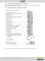
6.2.1 Terminal description -MASTER- and -SLAVE-
Illustration: Control board with terminals
1. Flushing valve switching output 230 ________________________
2. Flushing valve voltage output 230 V (only on 68604) ___________
3. Flushing valve N _______________________________________
4. Power supply - LI 230V__________________________________
5. Power supply – N ______________________________________
6. External input 230 V (Function only with -MASTER-) ___________
7. Grounded conductor PE _________________________________
8. CAN-Bus HIGH 1 ______________________________________
9. CAN-Bus LOW 1_______________________________________
10. CAN-Bus GND 1 ______________________________________
11. CAN-Bus HIGH 2 _____________________________________
12. CAN-Bus LOW 2______________________________________
13. CAN-Bus GND 2 ______________________________________
14 Flow measurement valve - Voltage output 5V ________________
15 Flow measurement valve - Flow input ______________________
16 Flow measurement valve - no function _____________________
17. Flow measurement valve GND ___________________________
18. Pt 1000 Input 1 _______________________________________
19. Pt 1000 Input 2 _______________________________________
20. Pt 1000 Input 3 _______________________________________
21. Pt 1000 Input 4 _______________________________________
22. Drain floating switch (strands interchangeable) ______________
23. Drain floating switch (strands interchangeable)
[Terminals 22 and 23 can also be used to connect
the water sensor]
PC-interface
__________________________
(only for –MASTER-:
jack plug, no clamp)
24. Alarm relay voltage input external ________________________
25. External monitor voltage error ___________________________
26. External monitor voltage operation ________________________
Ill. 6.2 Cut-out view of the -MASTER- and -SLAVE- controller board with terminals
Manual KHS Mini System Control MASTER
8
6.2.2 Detailed illustration of the terminals for cable entry
Note:
The following illustrations apply to the KHS Mini System Control
-MASTER- and the KHS Mini System Control -SLAVE-. Please note the
preceding warning notices.
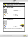
6.2.2.1
Power supply connection
Power supply: 230 V +/- 15% AC 50/60Hz
Connection: Terminals, L, N, PE
Line fuse max. 16A
BN = brown = L
BU = blue = N
GR = green = PE
Ill. 6.3: Schematic representation of the power supply connection
6.2.2.2
BN
Connection of KHS Isolating valve with servo-drive
(Figure 686 04 / 696 04)
BK
BN = brown = 1
BK = black = 2
BU = blue = 3
Ill. 6.4: Schematic representation of the connection of the KHS Isolating valve
Manual KHS Mini System Control MASTER
9
6.2.2.3
Connection of KHS Isolating valve with spring reset servo-drive
(Figure 686 05 / 686 15 / 696 05)
BN = brown = 1
BU = blue = 3
Ill. 6.5: Schematic representation of the connection of the KHS Isolating valve with
spring reset servo-drive
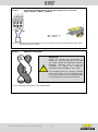
6.2.2.4
CAN bus connection
Attention:
Follow the notices and instructions in
Chapter 5. The twisted pair of the CAN
bus cable should be separated and the
shielding removed only as far as
necessary to assign the maximum
terminals (recommendation: max. 4cm).
The shielding must be properly bundled
with a heat shrink tube or insulating tape
to prevent contact of the individual wires
of the shielding to the other potentials.
Ill. 6.6: Schematic diagram of the twisted pair
Manual KHS Mini System Control MASTER
10
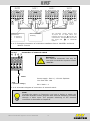
CAN bus H and L = 1
Twisted-Pair
H: Strand 1
L: Strand 2
The terminal groups 8/9/10 and
11/12/13 are of equal value. For
instance the wire end a can also be
connected to Terminals 11/12/13 and
the wired end
b
to Terminals
8/9/10.
Put on GND cable
shielding
Ill. 6.7: Exemplary illustration of a CAN bus installation from a -MASTER- and three
-SLAVE- controls
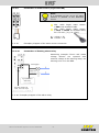
6.2.2.5
Connection of external switch
Attention:
The external connection can only be
used with the KHS Mini System Control
-MASTER-.
Switch
Power supply: 230V +/- 15% AC 50/60Hz
Line fuse max. 16A
230V
L (external voltage)
BK = black = L
Ill. 6.8: Schematic diagram of connection of external switch
Note:
Through the trigger on Terminal 6 you have a facility to switch the
KHS Mini System Control program with external switching processes
through a 230V input. The program switching of the external
connection is discussed in Chapter 8.
Manual KHS Mini System Control MASTER
11
6.2.2.6
Connection of KHS-CONTROL-PLUS flow measurement valve
(Figure 638 4G / 138 4G)
Connection of KHS-CONTROL-PLUS volume flow measurement valve
14 15 17
BR = +5V DC = 14
BU = Flow = 15
BK = GND = 17
Ill. 6.9: Schematic diagram of connection of KHS-CONTROL-PLUS flow
measurement valve
Connection of KHS-CONTROL-PLUS temperature sensor
Attention:
The KHS-CONTROL-PLUS
has
an
internal
Pt
1000,
enabling
an
additional temperature measurement.
If no temperature measurement is
needed or a Pt 1000 connected,
insulate and protect the strands from
contact with the board.
GY = grey (green/yellow) = 19
W = white = 20
Ill. 6.10: Schematic diagram of connection of KHS-CONTROL-PLUS volume flow sensor
Note
Attention:
To
perform
the
temperature
measurement
through
the
KHSCONTROL-PLUS, the jumper on the
board must be changed from 4-wire to
2-wire, see Photo 6.11.
Important comment:
During
this
measurement,
the
temperature measurement is falsified
through the line resistance. For 10m
line-length
with
0.34mm²
crosssection, the measurement falsification
can amount to approx. + 0.5°C.
Ill. 6.11: Schematic diagram of connection of KHS-CONTROL-PLUS temperature sensor
Manual KHS Mini System Control MASTER
12
Connection of KHS-CONTROL-PLUS cable-plug connector
1. Cut off top of cap
cap
2. Route cable through
3. Screw cable to sensor
4. Put on the
Ill. 6.12:
Schematic diagram of the preparation of the sensor top to make cableplug connection of the KHS-CONTROL-PLUS
6.2.2.7
Connection of KHS Temperature sensor Pt 1000 (Figure 628 0G)
RD = red = 18
RD = red = 19
W = white = 20
W = white = 21
Ill. 6.13:
6.2.2.8
Schematic diagram of connection of KHS Temperature Measurement
Valve Pt 1000
Connection of KHS drain with overflow monitor (Figure 688 00)
Note:
In the as delivered state, a bridge
strand is plugged between Terminals
22 and 23. It must be removed before
connecting the KHS drain.
W = white = 22
BN = brown = 23
Ill. 6.14:
Schematic diagram of connection of the KHS drain with overflow monitor
Manual KHS Mini System Control MASTER
13
6.2.2.9
Connection of water sensor (Figure 620 00)
Note:
It is possible to link up to 25 water
sensors in parallel in the detection
circuit.
Max. cable length water sensor:
< 50m with standard cable
Max. cable length water sensor:
> 50m to 500m as shielded cable,
2x 0.75 mm², (e.g. UL-LIYCY)
W = white = 22
BN = brown = 23
Ill. 6.15:
Exemplary diagram of the water sensor connection
6.2.2.10
Connection of floating alarm relay
Monitoring example: Errors and mains
voltage failures are reported with
external voltage to the warning lamp, the
warning horn or to the BMS.
Warning light
Alarm horn
e.g input BMS or
alarm relay
External voltage max.
230V, 2A or 24V input
Ill. 6.16: Exemplary diagram of the alarm relay
Manual KHS Mini System Control MASTER
14
7.
Commissioning
After finishing the wall installation and the electrical installation in accordance with
Chapter 5, apply the mains voltage of 230V.
Warning notice:
Allow only certified electricians to assemble and install electrical
equipment. Danger of fatal electric shock.
ATTENTION!
Note:
To simplify the control system and to guarantee flawless installation,
fill in the overview of the system commissioning of the KHS Mini
System Control (see supply pressure, Chapter 13.2) before making the
settings. It is mandatory to fill in the supply pressure to be able to take
advantage of the optional factory support.
Manual KHS Mini System Control MASTER
15
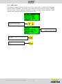
8.
Configuration
The KHS Mini System Control -MASTER- can be configured through the internal menu
driven operation or through a web server. Furthermore, the saved configurations can be
uploaded through a USB interface to the KHS Mini System Control -MASTER-.
The sample project shown below shows the basic controller types of the KHS Mini System
Control -MASTER-. The individual configuration facilities of the KHS Mini System Control
-MASTER- is elucidated using exemplary configurations of the sample project in the
following chapters (Ill 8.1 and 8.2).
After all units, as described in Chapter 6, have been mounted and electrically connected,
the actual configuration of the individual KHS Mini System Controls starts.
The sample project has one KHS Mini System Control -MASTER- and two KHS Mini
System Controls -SLAVE-. The system controls shown in Illustration 8.1 are intended to
secure the cold-water line against stagnation and leaks in a fictitious building.
Consumers
Sensor cable
230V cable
CAN bus cable
SLAVE 1.2
GF
Volume flow sensor 1;
Cellar
Valve
cellar
MASTER
SLAVE 1.1
Valve C1;
Cellar
Valve C2;
Cellar,
Water sensor 1-4; Cellar
Drain + overflow
monitor 1-2; Cellar
Cellar
Ill. 8.1 Sample project
Manual KHS Mini System Control MASTER
16
8.1
Manual configuration
Basic settings, configurations and changes can be made onsite by using the integrated
menus. In the following chapter, the menu interfaces and their functions are clarified. To
explain the settings and functions, the sample project is configured as a reference
building.
8.1.1 Basic menu operation and functions
The KHS Mini System Control is set and operated through various menus, which appear
in the -MASTER- display. Access to the menus is enabled through the control panel on
the -MASTER- with the four control buttons.
"ESC" button: Exit the menu / switch between
overview and main menu
"↑" button:
Scroll back
"OK" button: Confirm button
"↓" button:
Scroll forward
III. 8.2 -MASTER- buttons
The menus are structured "scrolling", i.e., pushing the "↓-button" on the last menu item
jumps back to the first menu item. Likewise, pressing the "↑-button" changes from the
first to the last menu item.
Note:
If no entry is made for three minutes, the control reverts from the
setting mode to the general plan.
Window types
Menu operation is divided into two sections. The following windows are available:
"General plan"
"Main menu".
The functions of the windows are listed in Table 8.1.
The "General plan" window is used only for visualising the current states.
In the "Main menu" window, preset parameters can be viewed, changed and
saved. The "Main menu" window can be protected against changes caused by
interference through password protection.
Tab. 8.1 Chart of window types
Window types
General plan
Main menu
Viewing possible without password
Viewing impossible without password
Functions:
Detailed overview
Control state display
View network
Device settings
Flushing processes
Error statuses
Function:
Setting the control parameters
CAN BUS setup
Select the operating modes
Journal
Program selection
Manual KHS Mini System Control MASTER
17
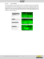
8.1.2 General plan
The following illustrations explain the "General plan" menu interface of the KHS Mini
System Control -MASTER-. The illustrations show the "General plan" based on an
exemplary configuration of a system with one KHS Mini System Control -MASTER- and
two KHS Mini System Controls -SLAVE-.
Sheet 1 of 8
Time (changes with date)
Program 1 activated
Volume flow sensor applied
Master
Flushing valve applied
"L" Leakage
Slave
Ill. 8.3 General plan 1/8
CAN-BUS activated
Time control activated
Temperature sensor applied
"Scroll back/forwards"
changes between Sheets 1 to 8
Sheet 2 of 8
Time (changes with date)
Empty slave slots (up to
62 system controls SLAVE- possible)
Ill. 8.4 General plan 2/8
Changes from "General plan" into "Detailed overview"
1x "OK" Selects control (frame*)
2x "OK" Changes into detailed
overview
*: A frame appears around the entry of the first
controller (see Ill 8.5 upper left) on the selected
sheet (1 to 8). Pressing the OK button again
opens the "Detailed overview" (see Ill. 8.6) of
the selected control. Optionally, press the ↑ or ↓
button to select another active controller. It is
indicated again through a flashing frame. If you
now press the OK button, the detailed overview
of another controller appears.
Ill. 8.5 Controller selection
Ill. 8.6 Detailed overview
Legend symbols
Water exchange activated:
Valve symbol is framed
Time control
-> Time symbol flashes
Volume control
-> Volume symbol flashes
Temperature control -> Temperature symbol flashes
Manual KHS Mini System Control MASTER
18
8.1.3 Detailed overview
The following illustrations clarify the "Detailed overview" menu interface of the KHS Mini
System Control -MASTER-. The illustrations show the "Detailed overview" based on an
exemplary configuration of a system with one KHS Mini System Control -MASTER- and
two KHS Mini System Controls -SLAVE-.
Serial number of the
controller including
symbols
Serial number
Time and date
"L" for leakage/protection
Name of the
controller
Controller-specific detailed
overview
Ill. 8.7 Detailed overview
"Scroll back/forwards"
changes between the active
controllers
1x "ESC" returns to the
general plan
Legend symbols
Water exchange activated:
Valve symbol is framed
Time control
-> Time symbol flashes
Volume control
-> Volume symbol flashes
Temperature control -> Temperature symbol flashes
Manual KHS Mini System Control MASTER
19
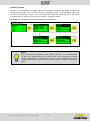
8.1.4 Main menu
The following chapters explain the functions of the "Main menu" interface of the KHS Mini
System Control -MASTER-. In the main menu there are the sub-menus: System settings,
Can-bus setup, Device settings, Operating modes, Journal, Switch program, Valve
manual mode, Network setup (see Ill. 8.8 and Ill. 8.9).
Ill. 8.8 Main menu "top"
"Scroll back/forwards"
Selection of the submenu
Scrollbar indicates the
position in the menu
Ill. 8.9 Main menu "bottom"
1x "OK" Changes into the selected
submenu
1x "ESC" returns to the main
menu
Manual KHS Mini System Control MASTER
20
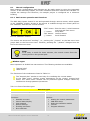
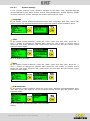
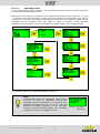
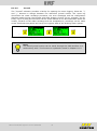
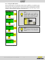
8.1.4.1
System settings
In the "System settings" menu interface, settings for the date / time, language daylight
savings/standard time, alarm buzzer, button acknowledgement, display lighting, display
contrast, password, factory settings and system reboot can be made.
Language
In the system control submenu select the menu item "Language" with "OK"; press "OK"
again to store the selected language and to open the system control submenu again.
Ill. 8.10 Setting the language
Time
In the system control submenu, select the "Time" menu item with "OK"; press the "↑"
and "↓" button to change the selected digit. Press the "OK" button to confirm and to
select the next digit. Pressing "OK" again stores the set time and the system control
submenu opens again.
Ill. 8.11 Setting the time
Date
In the system control submenu, select the "Date" menu item with "OK"; press the "↑"
and "↓" button to change the selected digit. Press the "OK" button to confirm and to
select the next digit. Pressing "OK" again stores the set date and the system control
submenu opens again.
Ill. 8.12 Setting the date
S/W automatic
In the system control submenu select the menu item "Daylight savings/Standard time"
with "OK"; press "OK" again to save the selected setting and to open the system control
submenu again.
Ill. 8.13 Daylight savings/Standard time automatic
setting
Manual KHS Mini System Control MASTER
21
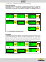
Alarm buzzer
If an error occurs in the system controllers, it can be acoustically reported. To activate
this function, select the menu item "Alarm buzzer" in the system control submenu with
"OK". Pressing "OK" again saves the selected setting; the system control submenu opens
again.
Ill. 8.14 Activating the alarm buzzer
Key press signal
The key press signal can be activated or deactivated through the "Key press signal
acknowledgement" menu item. To do that, select the "Key press signal
acknowledgement" menu item in the system control submenu with "OK". Pressing "OK"
again saves the selected setting; the system control submenu opens again.
Ill. 8.15 Activating the button
acknowledgement
Display contrast
Use the "Display contrast" menu item to set the display contrast. To do that, select the
"Display contrast" menu item in the system control submenu with "OK". Press the "↑" and
"↓" buttons to change the contrast. Pressing "OK" again saves the selected setting; the
system control submenu opens again.
Ill. 8.16 Display contrast
Display illumination
Use the "Backlight" menu item to
the last press of a button. To do
control submenu with "OK". Press
continues to illuminate. Save the
control submenu opens again.
set the operating time of the display illumination after
that, select the "Backlight" menu item in the system
the "↑" and "↓" buttons to change the time the display
selected settings by pressing "OK" again. The system
Ill. 8.17 Display illumination
Manual KHS Mini System Control MASTER
22
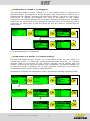
Password
To protect the controller from interference, a password can be configured. If a password
has been stored, the password will be queried before every setting (see Ill. 8.19). To do
that, select the "Password" menu item in the system control submenu with "OK". Use the
"↑" and "↓" buttons to select the digit. Press the "OK" button to confirm and to select the
next digit. Pressing "OK" again stores the set password and the system control submenu
opens again.
Ill. 8.18 Setting the password
Note:
The password "0000"
is the factory default
setting.
Ill. 8.19 Password query
Default settings
To reset the control to the default settings, select the menu item "Default setting" in the
system control submenu with "OK". A query then opens. If it is acknowledged with "OK",
the system is reinstalled.
Note:
All previous configurations will be lost!
Ill. 8.20 Restore the default settings
Restart the MASTER
To restart the controller, select the menu item "Restart MASTER" in the system control
submenu with "OK". A query then opens. If it is acknowledged with "OK", the system is
restarted.
Ill. 8.21 Restart -MASTER-
Manual KHS Mini System Control MASTER
23
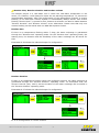
8.1.4.2
CAN BUS setup
Use the "CAN BUS setup" to add "SLAVE System Controls" that are connected to the MASTER 2.0- through the CAN bus system to the CAN BUS network.
The following configuration steps are discussed based on the sample project from
Illustration 8.1 (Page 16). For an overview of the system commissioning, Illustration 8.22
is presented.
-
Ill. 8.22 Overview for the system commissioning of the sample project
Adding devices
Before you can configure the KHS Mini System Controls, you have to add them to the
system.
To add a KHS Mini System control, the desired position has to be specified in the
"CAN-BUS Setup" submenu with "OK".
Subsequently, the serial numbers of all connected KHS Mini System Controls
-SLAVES- are shown.
Press the "↑" and "↓" buttons and confirm with "OK" to add the desired control.
The "CAN-BUS Setup" submenu then reopens.
Based on this scheme, all connected KHS Mini System Control -SLAVE- are added to the
-MASTER-.
001206
001187
001185
001278
Ill. 8.23 Adding devices
When all the devices have been added, they are displayed in the main view as shown in
Illustration 8.23.
Ill. 8.24 General plan
Manual KHS Mini System Control MASTER
Note:
Check to see if the antenna icon can
always be seen or if the LEDs glow green
on all KHS Mini System Controls. Only
then has a proper connection been
established.
24
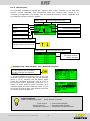
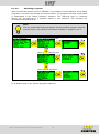
8.1.4.3
Device settings
In the "Device settings" submenu, the individual KHS Mini System Controls with the
integrated actuators and sensors are logically linked to each other. Illustration 8.25
shows an overview of the "Device settings" submenu. Press the "↑" and "↓" buttons and
confirm with "OK" to select the desired control. Then select the desired linking option
(controller type, valve type, sensor type, alarm relay display, operating cycles) with
"OK". After that, a selection opens in which the related component can be selected. Press
"OK" again to open the device-specific setting facilities. They are explained in detail
based on the sample project.
Device selection
Control type
…..
C-valve
safety/leak detection
03
04
Valve
Select sensor
Select sensor
…..
Alarm relay display
Delete operating cycles
Ill. 8.25 Overview of the "Device settings" submenu
Manual KHS Mini System Control MASTER
25
The following configuration steps are discussed based on the sample project from
Illustration 8.1 (Page 16). For an overview of the system commissioning, Illustration 8.26
is presented.
-
Ill. 8.26 Overview for the system commissioning of the sample project
Configuration -MASTER- (C-valve)
In the sample project being used, the KHS Mini System Control -MASTER- should trigger
a C-valve in the form of a VAV-maximum flow isolating ball valve with spring reset servodrive. Furthermore, a KHS-CONTROL-PLUS flow measurement valve is to be evaluated.
Additional settings for this operating mode are explained in Chapter 8.1.4.4. Illustration
8.27 shows the configuration of a C-valve.
Device selection
Control type
deactivated
C-valve
C-valve
03
04
safety/leakdetection
detection
safety/leak
Valve
Select sensor
Ill. 8.27 Configuration of C-valve
Manual KHS Mini System Control MASTER
26
Configuration of -SLAVE- 1.1 (safeguard)
In the sample project being used, the KHS Mini System Control -SLAVE 1.1- should act
as a leakage safeguard. The KHS Mini System Control –SLAVE 1.1- should trigger a KHS
Isolating valve with spring reset servo-drive as a safety valve. Additional settings for this
operating mode are explained in Chapter 8.1.4.4. Illustration 8.28 shows the
configuration of a safety device.
Device selection
Control type
C-valve
safety/leak detection
03
04
Valve
Ill. 8.28 Configuration of safeguard
Configuration of -SLAVE- 1.2 (C-valve)
The KHS Mini System Control -SLAVE- 1.2 in this sample project should trigger a C-valve
in the form of a KHS Isolating valve with spring reset servo drive. Furthermore a KHSCONTROL-Plus should be evaluated. Additional settings for this operating mode are
explained in Chapter 8.1.4.4. Illustration 8.29 shows the configuration of a C-valve.
Device selection
Control type
deactivated
C-valve
03
04
safety/leak detection
Valve
Ill. 8.29 Configuration of a safeguard
Manual KHS Mini System Control MASTER
27
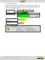
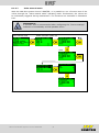
8.1.4.4
Operating modes
In the "Operating modes" submenu, the individual KHS Mini System Control programs
and times are added through lines.
Illustration 8.30 shows an overview of the "Operating modes" shows. Press the "↑" and
"↓" buttons and confirm with "OK" to select the desired control. Subsequently use "OK" to
select a line; each line can describe one program. A selection then opens to choose which
programs will be selected. Press "OK" again to open the specific setting facilities,
depending on the program. They are explained in detail based on the sample project.
Device selection
Choose line
Choose program
…..
03
04
…..
…..
…..
…..
…..
…..
Ill. 8.30 Overview of the "Operating modes" submenu
Note:
If the program switch is "Activated" (see Chapter
8.1.4.6), a query is presented during the
operating modes configuration to determine the
program this applies to (see Ill. 8.31). The two
mentioned flushing programs can be switched
using an external manual switch. The electrical
connection is shown in Chapter 6.2.2.5.
Manual KHS Mini System Control MASTER
28
Ill.8.31 Program
switching
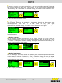
Configuration of -MASTER- (temperature/time flushing)
Temperature flushing
The KHS Mini System Control -MASTER- in the sample project is linked to a temperature
measurement valve. To control the temperature-dependent water exchange, the
"Temperature" program needs to be selected. The starting and stopping temperatures
and the maximum flushing time need to be set for the "Temperature" program.
Illustration 8.32 shows the configuration of the "Temperature flushing" operating mode.
Temperature flushing
Ill. 8.32 Configuration of temperature flushing
Time flushing
The KHS Mini System Control -MASTER- in this sample project is connected to a C-valve.
To time-control exchange the water, a line needs to be added with the "Cycle control"
program. When the program is selected, define the times. In the "Cycle control"
program, a starting time and the duration of the water exchange need to be stated.
Furthermore, the desired weekday can be selected through a dropdown list. Illustration
8.33 shows the configuration of a "Time control" operating mode.
03
04
Ill. 8.33 Configuration of time flushing
Manual KHS Mini System Control MASTER
29
Configuration of -SLAVE- 1.1 (safeguard)
The KHS Mini System Control -SLAVE- 1.1 in this sample project is planned as a
safeguard SLAVE. The safeguard is always activated using a water sensor. When a line is
selected with the "Release" program, the times can be defined. This valve is open only in
times-of-use. A starting and stopping time need to be defined for the release.
Furthermore, the desired weekday can be selected through a dropdown list. Illustration
8.34 shows the configuration of the "Safeguard" operating mode. If no operating mode is
configured, the safety valve is open the whole day and only reacts to a signal from the
water sensor.
Ill. 8.34 Configuration of a safeguard
Configuration of a -SLAVE- 1.2 (volume flushing)
The KHS Mini System Control -SLAVE- 1.2 in the sample project are each linked to a
volume flow sensor. To control the volume-dependent water exchange, the "Volume"
program needs to be selected. For the "Volume" program, set the starting time, the
flushing volume and the maximum flushing time. Furthermore, the desired weekday can
be selected through a dropdown list for both programs. Illustration 8.35 shows the
configuration of the "Volume flushing" operating mode
Illustration 8.35 shows the configuration of the "Temperature flushing" operating mode.
Volume flushing
01
02
03
04
Ill. 8.35 Configuration of volume flushing
Manual KHS Mini System Control MASTER
30
Routine-time, Routine-duration and Routine-volume
The sample project is a cold-water line in which the cold-water temperature in the
winter, for instance, could always lie below the set starting temperature. To prevent an
impermissible stagnation, after the configuration of the temperature flushing, a routine
flushing of the KHS Mini Control System is automatically always stored. The routine
flushing "Routine time"" is preset for this; however a selection can also be made between
"Routine duration" and "Routine volume" as an alternative. Please note that only one
routine flushing can be stored with one KHS Mini System Control.
Routine time
If there is no temperature flushing within 7 days, the water exchange is guaranteed
through the "Routine time" operating mode. For the "Routine time" operating mode, the
starting time, the duration and the weekdays of the water exchange can be stored for
that.
Illustration 8.36 shows the individual steps for configuration.
Ill. 8.36 Configuration of routine time
Routine duration
If there is no temperature flushing within the configured interval, the water exchange is
guaranteed through the "Routine duration" operating mode. To accomplish that, the
decisive interval (max. 168 h) and the duration of the water exchange can be stored in
the "Routine duration" operating mode.
Illustration 8.37 shows the individual steps for configuration.
Ill. 8.37 Configuration of routine duration
Manual KHS Mini System Control MASTER
31
Routine volume
If there is no temperature flushing within the configured interval, the water exchange is
guaranteed through the "Routine volume" operating mode. To accomplish that, the
decisive interval (max. 168 h), the volume and the maximum flushing time of the water
exchange can be stored in the "Routine volume" operating mode.
Illustration 8.38 shows the individual steps for configuration.
Ill. 8.38 Configuration of routine volume
Note:
After successfully configuring your system controls, it is recommended
to save the configuration as a backup file. If the KHS Mini System
Control -MASTER- is defective it can be quickly replaced and the
configuration can be read in. That saves having to configure everything
again.
Manual KHS Mini System Control MASTER
32
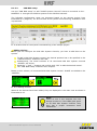
8.1.4.5
Journal
The "Journal" submenu provides a facility for opening the event logging. Press the "↑"
and "↓" buttons to change between the individual journal entries. The event log
documents the water exchange processes, the error messages and the configuration
changes made through the Kemper KHS Mini System Control (for an example, see Ill.
8.39). Up to 50,000 journal entries can be saved. Based on the documentation about the
locality, duration of the water exchange and the temperatures, recordings can be made
across a defined time period and verify the hygienic state of the drinking water system.
....
....
Ill. 8.39 Illustration of a journal entry index 9-10, configuration change
Note:
The stored journal entries can be saved through the USB interface on a
USB memory stick. This function is explained in detail in Chapter 8.1.5.
Manual KHS Mini System Control MASTER
33
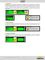
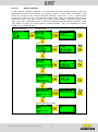
8.1.4.6
Switching programs
With the KHS Mini System Control -MASTER- it is possible to switch between two flushing
programs or to block one through an external switch. The programs can also be activated
or deactivated in the "Switch program" submenu. The "External input" or "External
switch" can be assigned to a program switch in this submenu. The functions are
described in Illustration 8.40.
Note:
The two mentioned flushing programs can be switched using an external
manual switch. The electrical connection is shown in Chapter 6.2.2.5.
Progr. Switchover
Progr. switchover deactivate
Block system/select program
Select external input action
Ill. 8.40 Overview of the "Switch program" submenu
Manual KHS Mini System Control MASTER
34
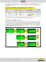
8.1.4.7
Valve manual mode
With the KHS Mini System Control -MASTER-, it is possible to run a function test of the
valves through the "Valve manual mode" operating mode. Furthermore, the valves can
be individually triggered during maintenance. The functions are simulated in Illustration
8.41.
Maintenance:
A function test is recommended after configuring the "Device settings"
submenu to immediately exclude possible errors.
Valve manual mode
Select automatic system ctrl.
Open
Closed
Ill. 8.41 Overview of the "Valve manual mode" submenu
Manual KHS Mini System Control MASTER
35
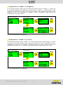
8.1.4.8
Error handling
All the errors that occur in the system are sent to the KHS Mini System Control -MASTERand are signalled acoustically through a buzzer. It is possible to integrate an alarm relay
(see Chapter 6.2.2.8). In normal operation, the alarm relay is energized ("pulled") with
voltage. If there is an error, the voltage drops and an acoustic signal reports the error.
During this it does not matter what kind of impact the malfunction could have on the
system. The control goes into alarm latching and has to be acknowledged after the
malfunction has been repaired.
Switch off / acknowledge buzzer
1 x OK Buzzer off
The control remains in alarm
latching
Ill. 8.42 Acknowledge the buzzer
Error display
The errors of the MASTER / SLAVE
controls are displayed flashing in the
general plan with a lightning icon
Change into the detail view
2 x OK Selected control
Ill. 8.43 Error display
Acknowledge error
After the malfunction has been
repaired, the malfunction can
be acknowledged in the detail
display
1 x OK Acknowledge error
Ill. 8.44 Acknowledge the error
Manual KHS Mini System Control MASTER
36
8.1.5 Using the USB interface
With the USB interface of the KHS Mini System Control -MASTER-, it is possible to copy
the journal (CSV file), the configuration of the system controls (CFG file) and the datalog
(CSV file) onto a USB memory stick. Furthermore, backed-up configurations (CFG file)
and new software updates (UPD file) can be written to the KHS Mini System Control
-MASTER-. The functions are simulated in Illustration 8.45.
Copying the
journal
Note:
The USB menu is not visible in
normal
mode.
The
menu
is
automatically activated when a USB
memory stick is connected to the
KHS Mini System Control -MASTER-.
Copy the configuration
Read-in the configuration
Note:
After selecting a menu item, follow
the instructions on the subsequent
display.
Copy datalog
Software update
Ill. 8.45 Overview USB menu
Manual KHS Mini System Control MASTER
37
8.2
Configuration PC-software
Note:
The configuration of the PC-software is explained in a separate
operating instruction. You find this manual on our website
www.kemper-olpe.de or with the PC-software itself.
To use the PC-software, a USB adapter cable (figure 686 02 016) is
needed.
Manual KHS Mini System Control MASTER
38
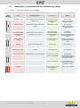
9.
Description of malfunctions and malfunction repair
Table 9.1: Error description / Error handling
Error description / Error handling
Status
LED
on Slave
Error
Potential cause
Measures
Impact
Backwater in drain
Drain is clogged or cannot accept the
flushing volume.
Check the drain channel,
channel acceptance
capacity.
Error message!
Defective control will be
completely blocked
Backwater in drain
Float switch on the drain has a cable
break
Replace cable / switch
Error message!
Defective control will be
completely blocked
Leak on sensor
Pipe failure, moisture on the sensor
Temperature flushing
switched off during
runtime
Medium did not reach the switch-off
temperature in the set time
Check the local area and
remove the moisture
Check the installation
setup and the maximum
flushing time.
Volume flushing
switched off during
runtime
Set volume not reached
Check the installation
setup and the maximum
flushing time.
The safety valve is blocking
the system.
Error message!
Temperature operating mode
is blocked in the defective
control.
Error message!
Volume operating mode is
blocked in the defective
control.
"Flow with closed valve
detected"
Flow is detected by the vortex flow
sensor with the valve closed
Check the functioning of
the flush valve
Error message! The involved
valve is blocked.
"No flow detected
although valve is open"
No flow is detected during a flushing
process.
Check the flushing line and
the flushing valve
Error message! The involved
valve is blocked.
PT1000 value too high
Sensor defective / No sensor available
Replace sensor / Check
inputs on the MASTER
Error message!
Temperature flushing
operating mode is blocked in
the defective control.
PT1000 value too low
Sensor defective / No sensor available
Replace sensor / Check
inputs on the MASTER
Error message!
Temperature flushing
operating mode is blocked in
the defective control.
Real-time clock data
inconsistent
Data in the clock are not consistent
Check the time & date and
adjust if necessary. Check
battery/replace if
applicable
All time-based services are
running on false time/date.
Only Master
flashes red
(1 per sec.)
Fashes red
(1 per sec.)
Flashes red
(5 per sec.)
Permanent flashing
red
General error
Manual KHS Mini System Control MASTER
39
Error description / Error handling
Status
LED
on Slave
Error
Potential cause
Measures
Impact
No response from the
SLAVE
Cable break, false installation,
interference fields
Check CAN bus cables
and installation
Faulty SLAVE does not
function
No response from the
SLAVE
SLAVE does not have voltage
Restore SLAVE power
supply
Faulty SLAVE does not
function
No response from the
SLAVE
SLAVE with its corresponding serial
number no longer part of the plant
(e.g., after a replacement)
Assign the correct serial
number to the SLAVE or
delete the device from the
system
Faulty SLAVE does not
function
CAN bus line fault
Cable break, false installation,
interference fields
Check CAN bus cables
and installation
CAN-BUS and all SLAVEs do
not function.
Too many bus
subscribers
CAN-BUS A
More than 31 SLAVEs are connected
to
CAN-BUS A
Rewire or the BUS
subscribers or change the
position of the MASTER in
the bus system.
CAN-BUS A faulty.
Communication and functions
can be impaired.
Too many bus
subscribers
CAN-BUS B
More than 31 SLAVEs are connected
to
CAN-BUS B
Rewire or the BUS
subscribers or change the
position of the MASTER in
the bus system.
CAN-BUS B faulty.
Communication and functions
can be impaired.
Communication error
CAN Bus A
Cable break, false installation,
interference fields
Check CAN Bus A cables
and installation
Affected SLAVEs do not
function
Communication error
CAN Bus B
Cable break, false installation,
interference fields
Check CAN Bus B cables
and installation
Affected SLAVEs do not
function
Only on Master
Flashes orange
(5 per sec.)
Flashes orange
(5 per sec.)
Bus error
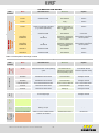
Table 9.2: Description of warnings / notices
Description of warnings / notices
Status
LED
on Slave
Error
Potential cause
Measures
Impact
Operating cycles exceed
10,000
The VAV on the defective SLAVE has
performed more than 10,000 operating
cycles
Replace VAV bonnet in
accordance with the
maintenance manual and
reset the operating cycles
The warning message cannot
be confirmed. SLAVE
continues to operate normally
Limit thermal disinfection
exceeded
The monitored temperature has
exceeded the set limit value
Check to see if it needs to
be set otherwise
Entry in journal and optional
message via email
Limit set-point max.
exceeded
The monitored temperature has
exceeded the set limit value
Check to see if it needs to
be set otherwise
Entry in journal and optional
message via email
Limit set-point min.
undercut
The monitored temperature has
undercut the set limit value
Check to see if it needs to
be set otherwise
Entry in journal and optional
message via email
Frost protection limit
undercut
The monitored temperature has
undercut the set limit value
Prevent danger of valves
freezing up
Entry in journal and optional
message via email.
Set-point OK
Notice that the monitored temperature
is in the target range
No action needed!
Entry in journal and optional
message via email
Control in standby
No flushing pending. Control in standby
No action needed!
No influence
Flushing is running
The valve on the involved control is
flushing / is open
No action needed!
Entry in journal
Control unit is disabled
System control is installed correctly,
however not activated
Activate system control
No influence
No influence
Flashes
red
(1/ sec.)
Warnings
influence
Flashes green
and orange in
an alternating
sequence of
1 sec
Flashe
s green
Illuminates
green
No
Notes
Manual KHS Mini System Control MASTER
40
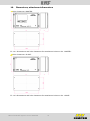
10.
Dimensions, attachment dimensions
Hole clearances -MASTER-
Ill. 10.1 Dimensions and hole clearances for attachment holes on the -MASTERHole clearances -SLAVE-
Ill. 10.2 Dimensions and hole clearances for attachment holes on the -SLAVE-
Manual KHS Mini System Control MASTER
41
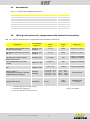
11.
Accessories
Tab. 11.1 Optionally available accessories
Optionally available accessories
FIGURE
KHS Isolating valve with servo drive 230 V
KHS Isolating valve-plus with spring-reset servo drive (230 V)
KHS drain with overflow monitor
KHS temperature sensor fitting PT 1000
KHS flow measurement valve
686 04
686 05
688 00
628 0G / 629 0G
638 4G / 138 4G
Leakage water sensor
620 00 001
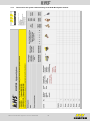
12.
Wiring instructions for components with electrical connection
Tab. 12.1 Wiring instructions for components with electrical connection
Cable crosssection
mm²
Max. cable
length
m
Cable type*
KHS Isolating valve-plus with spring- 68605015…032
reset servo drive (230 V)
69605015
3 x 1.5²
9500
NYM-J 3 x 1.5mm²
KHS Isolating valve with servo drive
(230 V)
68604015…032
69604015
4 x 1.5²
9500
NYM-J 4 x 1.5mm²
KHS drain with overflow monitor
68800020...032
2 x 0.25²
150
J-Y(ST)Y 1x2x0.6mm²
or NYM-J 3x1.5mm²
Kemper Control-plus
Flow measurement valve Vortex
principle
6384G015…025
1384G015…050
7 x 0.34² **
300
J-Y(ST)Y 4x2x0.6mm²
KHS temperature sensor fitting PT
1000
6280G015...050
6290G015...050
4 x 2 x 0.6
10,000
J-Y(ST)Y 4x2x0.6mm²
CAN bus cable'***
The application is based on the ISO
11898 international standard.
68602005
68602006
1 x 2 x 0.25² ... 0.34²
1 x 2 x 0.34² ... 0.5²
1 x 2 x 0.50² ... 0.6²
1 x 2 x 0.75² ... 0.8²
0 m … 40 m
40 m … 300 m
300 m … 600 m
500 m … 1000 m
CAN bus cable
Leakage water sensor
6200000100
2x0.75²
0-50
50-500
Standard cable
UL-LIYCY
Designation
For KEMPER
order no.
* Possible cable type for fixed routing
** Shielded cable supply line
*** (To be provided by construction site)
Manual KHS Mini System Control MASTER
Version: 21/11/2013
42
13.
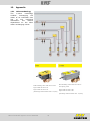
Appendix
13.1
Valve technology
The
C-valve
technology
enables
exchanging
the
water of an individual riser
line
or
one
individual
distribution
line
without
dependence on the other
water exchanging valves.
KHS Isolating valve with servo drive
Figure 686 04 230 V AC
Figure 696 04 230 V AC
(Discharge water limited max. 2 l/min)
Manual KHS Mini System Control MASTER
43
KHS Isolating valve with servo drive
and spring reset
Figure 686 05 230 V AC
Figure 696 05 230 V AC
(Discharge water limited max. 2 l/min)
13.2
Overview for the system commissioning of the KHS Mini System Control
Manual KHS Mini System Control MASTER
44
Manual KHS Mini System Control MASTER
45
NOTES:
Manual KHS Mini System Control MASTER
46
K410068602005-00 09/14
We reserve the right to make technical changes
Contact to manufacturer
Gebr. Kemper GmbH + Co. KG
Metallwerke
Harkortstr. 5
D-57462 Olpe
Tel. +49 2761 891-0
Fax +49 2761 891-175
[email protected]
www.kemper-olpe.de