1
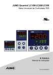
Digital 2-channel
microprocessor
indicator
B 95.1510
Operating Instructions
3.99/00085790
Operating scheme
Contents
1
Description
1.1
1.2
1.3
Type designation ................................................................................................................. 3
Technical data ..................................................................................................................... 5
Indications and controls ..................................................................................................... 7
3
2
Installation
2.1
2.2
2.3
Location and climatic conditions ........................................................................................ 8
Mounting in position ........................................................................................................... 8
Dimensions ......................................................................................................................... 8
3
Electrical connection
3.1
3.2
Connection diagram ............................................................................................................ 9
Important installation notes ............................................................................................... 11
4
Operation
4.1
4.2
4.3
Levels and inhibits ...............................................................................................................12
Indicated measured value ................................................................................................... 13
Table of callable variables ....................................................................................................13
5
Parameter level (alarms)
5.1
5.2
5.3
Alarms ..................................................................................................................................14
Indication and alteration of alarm settings ..........................................................................14
Limit comparator functions ..................................................................................................15
6
Configuration level
6.1
6.2
6.3
Finding subdirectories .........................................................................................................17
Displaying and editing configuration data ........................................................................... 17
Configuration tables ............................................................................................................18
7
Action on faults
7.1
7.2
7.3
Error message ..................................................................................................................... 25
Action on supply failure .......................................................................................................25
Action on overrange or underrange .....................................................................................25
8
Adjustments inside the instrument
26
9
Extra functions
28
9.1
9.2
9.3
9.4
9.5
9.6
Functions of the external contacts ......................................................................................28
Scroll function (automatic display change) ..........................................................................29
Humidity measurement ........................................................................................................ 30
Ratio measurement .............................................................................................................30
Difference measurement ......................................................................................................30
Segment test and call-up of software version .....................................................................30
10
User-specific settings
10.1
10.2
10.3
10.4
10.5
10.6
Actual value correction ........................................................................................................ 31
Calibration of indication .......................................................................................................32
Calibration of start and end of output signal .......................................................................32
Determining the cold junction temperature for thermocouples ...........................................33
Customer-specific linearisation ...........................................................................................34
Table of settings ................................................................................................................... 36
11
Retrofitting of cards
8
9
12
14
17
25
31
37
NOTE
All necessary settings and, where appropriate, alterations are described in these Operating Instructions.
If, however, any difficulties should arise during start-up, you are asked not to carry out any manipulation
on the instrument which is not permitted. – You could endanger your rights under the warranty.
Please contact the nearest office or the main factory.
1 Description
Introduction
The indicator MDA2-48, with a size of 96 x
48 mm and a depth of 174 mm behind the
panel provides a large number of functions.
The two configurable analog inputs permit
direct connections to thermocouples or resistance thermometers to DIN IEC, resistance transmitters, or transducers with a
standard signal.
The 14 mm high 4½-digit LED display indicates the measured value in normal operation and the input parameters at the function levels PARAMETERS and CONFIGURE.
A large number of standard factory settings
can be freely configured over wide ranges.
The individual levels can be inhibited to
prevent unintended changes. Functions
such as key inhibit, storage of reading and
maximum or minimum value, auto-tare or
blank display, can be activated through two
external contacts. Three outputs are available, depending on configuration, to output
the actual value (fully isolated) or as a limit
comparator for signalling alarms.
The RS232C (V.24) or R422/485 interface
(also isolated) has a transfer rate that can
be adjusted in the range 150 — 9600 bit/sec. The standard supply voltage is 93 — 263 V
AC. Operation on 20 — 47 V AC or 24 — 63 V DC is available to special order. A voltage
output 20 V / 22 mA to supply 2-wire transmitters is available as an extra Code.
The instrument conforms to Class KWF of DIN 40 040 and is suitable for ambient temperatures from 0 to 50°C.
1.1
Type designation
MDA2-48/... ,.. , .. – .... , .... – .... , ..
➊ , ➋ , ➌ –➍ , ➎ – ➏ , ➐
➊ Signal input 1
Resistance thermometers in 3-wire circuit
Pt 100
001
Pt 500
002
Resistance transmitters
(specify start and end of range in full)
021
Thermocouples
Cu-Con
Fe-Con
Cu-Con
Fe-Con
NiCr-Ni
Pt10Rh-Pt
Pt13Rh-Pt
Pt30Rh-Pt6Rh
MoRe5-MoRe41
T
J
U
L
K
S
R
B
039
040
041
042
043
044
045
046
047
Temperature compensation internal or external with
Pt 100 or cold junction thermostat.
Linearised transducers
0 — 1 mA
0 — 20 mA
4 — 20 mA
0 — 50 mV
0— 1V
0 — 10 V
Non-linearised transducers
0 — 1 mA (specify range)
0 — 20 mA (specify range)
4 — 20 mA (specify range
0 — 50 mV (specify range)
0 — 1 V (specify range)
0 — 10 V (specify range)
Linearisation to customer‘s values,
max 40 points, input signal as above
051
052
053
061
062
063
1 . . **
2 . . **
3 . . **
4 . . **
5 . . **
6 . . **
. 99
** instead of the two dots, enter the last two
numbers of the thermocouple code:
e.g. 241 = input 0 — 20 mA, 41 means
linearisation for Cu-Con U
3
1 Description
➋ Signal input 2
lk8 referred to input 2
not used
00
Difference input (transducer as input 1)
01
Display of a second measurement
(transducer as input 1)
02
Cold junction temperature
(Pt 100 in 3-wire circuit)
03
Ratio input,
transducers 0/4 — 20 mA, 0 — 10 V
resistance transmitters
(transducer as input 1)
05
Humidity input (psychrometric)
(both transducers Pt 100)
06
➌ 2 logic control inputs
(First function on contact 1, second
function on contact 2)
not used
Key inhibit + blank display
Auto-tare + reset
Measurement store + reset
00
14
23
56
➍ , ➎ Output 1, 2
Functions of output
not used
Actual value output channel 1
Actual value output channel 2
0000
8. . .
2. . .
Output signal (specify range)
0 — 20 mA
4 — 20 mA
–20 / 0 / +20 mA
0 — 10 V
–10 / 0 / +10 V
.400
.500
.600
.700
.800
Limit comparator output signal
Relay
0/5 V, Ri = 250 Ω
Semiconductor relay 1 A
51 . .
52 . .
53 . .
Function
not used
lk1 referred to input 1
lk2 referred to input 1
lk3 referred to input 1
lk4 referred to input 1
lk5 referred to input 1
lk6 referred to input 1
lk7 referred to input 1
lk8 referred to input 1
lk7 referred to input 2
. . 00
. . 11
. . 12
. . 13
. . 14
. . 15
. . 16
. . 17
. . 18
. . 27
4
. . 28
➏ Output 3
Function
not used
Auxiliary supply for 2-wire transmitter
20 V / 22 mA
0079
Limit comparator output signal
Relay
0/5 V, Ri = 250 Ω
Semiconductor relay 1 A
51 . .
52 . .
53 . .
Function
no function
lk7 referred to input 1
lk8 referred to input 1
lk7 referred to input 2
lk8 referred to input 2
. . 00
. . 17
. . 18
. . 27
. . 28
0000
➐ Extra Codes
Interface RS232C (V.24)
Interface RS422/485
51
52
1 Description
1.2
Technical data
Indicator for use with resistance thermometers
Input
Pt 100, Pt 500 in 3-wire circuit
Indication range –200.0 to +850.0°C
(°C or °F)
Line balance
not required with 3-wire circuit. Line balancing is required when using a resistance thermometer in 2-wire circuit. Line balancing can take place either at the configuration level
or by using an external line-balancing resistor.
Rbalance = Rline
Indicator for use with thermocouples
Input
Cu-Con U, Fe-Con L, Cu-Con T, Fe-Con J, NiCr-Ni K, Pt10Rh-Pt S,
Pt13Rh-Pt R, Pt30Rh-PtRh B or MoRe5-MoRe41 to IEC or ISA
Indication
ranges
(°C or °F)
Cu-Con
U
Cu-Con
T
NiCr-Ni
K
Pt13Rh-Pt R
MoRe5-MoRe41
Temperature
compensation
can be configured internally or externally or with an external cold junction.
–200 to + 600°C
–200 to + 400°C
–200 to +1400°C
0 to +1800°C
0 to +2000°C
Fe-Con
L
Fe-Con
J
Pt10Rh-Pt S
Pt30Rh-PtRh B
Indicator for use with linearised transducers with standard signal
(current or voltage)
Input
0 — 1 mA
Ri = 50 Ω
0 — 50 mV
0— 1V
0/4 — 20 mA
Ri = 2.5 Ω
0 — 10 V
–200 to +1000°C
–200 to + 900°C
0 to +1800°C
–200 to +1820°C
Ri more than 100 kΩ
Ri = 50 kΩ
Ri = 500 kΩ
Indication range can be freely configured
Indicator for use with non-linearised transducers with standard signal
Input
as for linearised transducers with standard signal
Indication range value assignment and linearisation can be configured.
Indicator for use with resistance transmitters
Input
range: min. 0 — 30 Ω, max. 0 — 10 kΩ
Indication
can be configured within the range –19999 to +1999 digit.
General data
Outputs
3 configurable outputs are available
Output 1,
Output 2,
Output 3
Output 1 and
Output 2 only
1.
Relay outputs with floating contacts
Rating:
660 W 3A at 220 V 50 Hz resistive load
Contact life:
approx. 106 operations at rated load
2.
Logic output
3.
Semiconductor relay output 1 A at 220 V 50 Hz, p.f. 0.7 min
4.
Actual value output (isolated)
switch-selected
0 — 20 mA
4 — 20 mA
–20 / 0 / +20 mA
0 — 10 V
–10 / 0 / +10 V
0/5 V or 0/20 mA
Ri = 250 Ω
burden resistor
500 Ω max.
500 Ω max.
500 Ω max.
500 Ω min.
500 Ω min.
5
1 Description
Output 3 only
5.
Voltage output for 2-wire transmitter 20 V / 22 mA, short-circuit proof, isolated.
D/A converter
Resolution 13 bit
Output signal
accuracy
0.25 % or better, referred to signal span.
A/D converter
Resolution 16 bit
Sampling rate
Channel 1
400 msec
Indicator accuracy
Channel 2
800 msec
Ambient temperature error
when used with resistance thermometers and resistance transmitters
0.05% or better
0.01%/10°C or less
when used with thermocouples within their working range
0.25% or better
0.05%/10°C or less
when used with linearised transducers with standard signal
0.15% or better
0.1%/10°C or less
* These values are based on the particular span, and include the linearisation tolerances.
Signal circuit
monitor
(Sensor break or short-circuit) The outputs move to a predefined status.
Isolation
between inputs
outputs to inputs
– for actual value output
– for interface
Data storage
EEPROM
Supply
normally:
to special order:
∆ Umax = 5 V
∆ Umax = 50 V
∆ Umax = 50 V
93 — 263 V AC 48 — 63 Hz
20 — 43 V AC 48 — 63 Hz
24 — 63 V DC
Power
consumption
8 VA approx.
Electrical
connection
through faston tags to DIN 46 244/A, 4.8 x. 0.8 mm
Ambient
temperature
Permitted range is 0 to 50°C
Storage
temperature
Permitted range is –40 to +70°C
Climatic
conditions
Class KWF to DIN 40 040, relative humidity not exceeding 75 % annual mean,
no condensation.
Case
Extruded aluminium sections, black anodized, with plug-in chassis.
Protection
to DIN 40 050, front IP54, rear IP20
Operating
position
unrestricted
Interfaces
RS232C (V.24) or RS422/485 (isolated from the remaining electronics)
Instrument addresses can be configured on RS422/485.
Operating mode: communication mode.
Standard
accessories
Operating instructions
Mounting brackets
6
1 Description
1.3
Indications and controls
➊
4½-digit numerical LED display
14 mm high
➏
Increment key for changing
a digit during programming
➋
Channel indication
Input 1
➐
➌
Digit key for selecting
the digit to be changed
during programming
Channel indication
Input 2
➑
Programming key for
selecting the individual
levels or subdirectories
( in conjunction with
the i and s keys)
and storing the inputs
➍
Output signal indication
of limit comparator 1
➎
Output signal indication
of limit comparator 2
7
2 Installation
2.1
Location and climatic conditions
The instrument location should be as
free from vibrations as possible.
Electromagnetic fields, caused, for
instance, by motors, transformers
etc., should be avoided. The ambient temperature at the instrument location may be between 0 and 50°C,
at a relative humidity not exceeding
75%. An aggressive atmosphere or
fumes reduce the life of the instrument.
2.2
Mounting in position
The indicator is inserted from the
front into the panel cut-out. Behind
the panel, the mounting brackets are
hooked into the recesses at the
sides of the case. The flat sides of
the brackets must be against the
case. Place the brackets against the
back of the panel and tighten them
evenly with a screwdriver.
2.3
8
Dimensions
3 Electrical connection
3.1
Connection diagram
The electrical connections have to
be made according to the connection scheme below. The choice of
cable and the connection of the supply line must conform to the requirements of VDE 0100 “Regulations on
the Installation of Power Circuits with
nominal voltages below 1000 V” or
the appropriate local regulations.
The diagram on the right shows the
rear view, with faston connectors.
Connection for
Terminals
Diagram
Output
No.
Relay output *
Actual
value
output
SCR
output **
Logic control
output
0/5 V Ri=250Ω
Relay,
semiconductor
relay,
logic outputs,
or actual value
output
1
42 n.o. (make)
43 common
42 –
43 +
42
43
42 –
43 +
2
52 n.o. (make)
53 common
52 –
53 +
52
53
52 –
53 +
Switching output
or supply for
2-wire transmitter
3
45 common
46 n.o. (make)
or 20 V / 22 mA voltage
supply
45
46
45 +
46 –
L1 line
N neutral
PE ground
L+
L–
Supply as on
label
AC / DC
Signal input
Terminals
AC
DC
Input
Thermocouple
1
2
111
112
211
212
+
–
Resistance
thermometer
in 3-wire circuit
111
112
113
211
212
213
With humidity measurement,
input 1 is wet temperature,
input 2 is dry temperature
Resistance
thermometer
in 2-wire circuit
111
112
113
211
212
213
Standard signal
current/voltage
111
112
211
212
+
–
Resistance
112
transmitter with
111
3-wire connection 113
212
211
213
S = slider
E = end
A = start
* Contact protection circuit 22 nF 56 Ω
** Varistor protection circuit 300 V
9
3 Electrical connection
Connection for
Terminals
External contact 1
81
82
floating contact
External contact 2
83
82
floating contact
Serial interface
RS232C (V.24)
Serial interface
RS422
Serial interface
RS485
10
RXD
91
Received data (receiving line)
TXD
93
Transmitted data (transmitting line)
CTS
92
Clear to send (ready to send)
RTS
94
Request to send (switch on transmitter)
GND
90
Signal ground
RXD
91 +
92 –
Received data (receiving pair)
TXD
93 +
94 –
Transmitted data (transmitting pair)
GND
90
Signal ground
RXD /
TXD
93 +
94 –
Transmitted/received data
(transmitting/receiving pair)
GND
90
Signal ground
3 Electrical connection
3.2
Important installation notes
h Work inside the instrument must only be carried out by specialist personnel and to the
extent indicated. This also applies to the electrical connection.
h Isolate the instrument from the supply on both poles if there is a possibility of touching
live parts during the work. The chassis is automatically isolated from the supply when
it is pulled out.
h A built-in current limiting resistor interrupts the supply circuit in the event of a shortcircuit. The external fuse of the supply should not be rated higher than 1 A (slow).
In order to prevent welding of the output-relay contacts in the event of an external
short-circuit in the load circuit, this must be fused for the maximum relay current (3 A).
Fuse the semiconductor relay circuit at 1 A.
h There should be no magnetic or electric fields in the vicinity of the instrument (e.g.
fields caused by transformers, radio-telephones, or electrostatic discharges).
h Inductive loads (relays, solenoid valves etc.) should not be mounted close to the
instrument, and should be fitted with RC modules to prevent interference.
h Input, output and supply lines should be physically separated and not routed parallel
to each other.
Out and return lines should be laid next to each other, and twisted together if possible.
h Sensor and interface lines should be laid as twisted and screened cables. Do not route
them close to current-carrying components or wiring. Ground the screen at one end to
the PE terminal on the instrument.
h Ground the PE terminal of the instrument to the protective earth of the supply. This
wire must have a cross-section as least as great as the supply lines. Route the ground
lines in a star configuration to a central grounding point that is connected to the
protective ground wire of the supply. Do not loop ground lines, i.e. running them from
one instrument to another.
h Do not connect any other loads to the supply terminals on the instrument.
h The instrument is not suitable for installation in hazardous areas subject to a danger of
explosion.
If both analog inputs are being
used, the potential difference
between the negative connections
must not exceed 5 V !
11
4 Operation
4.1
Levels and inhibits
For a clear presentation of the large
number of possible adjustments, the
parameters are arranged on three
separate levels: operating level, parameter level and configuration level.
Standard display/operating level
The display normally shows the actual value for input 1. A different
standard display can be selected at
the configuration level (C 313).
The change to the operating level is
operated by the Pgm key. The measurement of input 2, the stored measurements, minimum or maximum
values, can be checked here in sequence (see Section 4.3).
Parameter level
The settings for the three alarm outputs are made here.
Configuration level
This level is used for adapting the inputs and outputs of the indicator,
and for setting the required functions. The card-recognition of the
option cards ensures that only those
parameters are requested that correspond to the existing hardware. Internal DIL switches determine whether the indicator operates with the
factory-set configuration data, or
whether the data that are input by
the user are applied.
The three levels can be inhibited with
internal switches (see Section 8).
12
Level
Inhibit
Operating level
access possible
Parameter level
access possible
Configuration level
access possible
4 Operation
4.2
Indicate measured value
In the standard display, the indicator
normally shows the actual value on
channel 1.
Other values can be selected under
Code C 313 in the subdirectory
Sd03 at the configuration level (see
Section 6.4).
The LEDs CH1 and CH2 indicate
which channel is being displayed at
present. If measurements are combined (e.g. difference value) then
both LEDs light up. If one of the
channel LEDs blinks, this means that
a stored value for this channel (e.g.
minimum value) is being displayed.
Pressing the Pgm key changes to
the operating level. A symbol for the
measurement is displayed (e.g. InP2,
see Table 4.3 below), and the corresponding value when Pgm is
pressed again. If other variables
have been configured, they can be
called up in the same way. After the
last value, the instrument setting returns to the standard display.
If no key has been operated for 30
sec. the instrument also returns to
the standard display. The period
for this time-out can be altered in
the subdirectory Sd05 at the configuration level.
4.3
Table of variables that can be called up
Variable
Symbol
Actual value at input 1
InP1
Difference, humidity, or ratio value (actual)
ACt
Actual value at input 2
InP2
Maximum value at input 1 (High 1)
HI1 *
Maximum value at input 2 (High 2)
HI2 *
Minimum value at input 1 (Low 1)
Lo1 *
Minimum value at input 2 (Low 2)
Lo2 *
Stored value at input 1 (Hold 1)
HoL1 *
Stored value at input 2 (Hold 2)
HoL2 *
* These functions are activated through external contacts, see Section 9.1
13
5 Parameter level (alarms)
5.1
Alarms
Two independent limit comparators
with 8 functions, and one limit comparator with two functions, recognise
and signal if limits are exceeded.
This is indicated by the two LEDs K1
and K2. The third output (limit comparator) does not have an indicator.
The output is, depending on the order specification, a relay, a logic level
0/5 V or a 1A semiconductor relay.
The alarm is cancelled as soon as
the alarm condition is no longer
present. The functions of the limit
comparators lk1 to lk8, the reference
value XB and the switching differential Xd are all set in the subdirectory
Sd02 at the configuration level.
The possible limit comparator functions are described on the following
pages.
5.2
Indication and alteration of alarm
settings
Pressing the i and Pgm keys
simultaneously
accesses
the
parameter level. The display shows
the parameter symbol AL 1 for the
first alarm output. The corresponding
setting is displayed when the s key
is pressed.
The value can be altered by using
the s key to select the digit and the
i key to increment it. The value is
entered with Pgm. Pressing Pgm
twice calls up the second alarm
output with the symbol AL 2, whose
setting can be altered in the same
way. Pressing again calls up AL 3.
Parameter level
Parameter
Symbol
Threshold for Alarm 1 *
AL 1
Threshold for Alarm 2 *
AL 2
Threshold for Alarm 3 *
AL 3
* Adjustment range ±19999 digits
14
5 Parameter level (alarms)
5.3
Limit comparator functions
The differential Xd and the reference
value XB are set in subdirectory
Sd02. The alarm setting AL is selected at the parameter level.
➊ Function lk1
Window function: the relay is energised when the indicated value is
within a defined range.
Example:
XB = 200°C, AL = 20, Xd = 10
Actual value rising: relay switches on
at 185°C and off at 225°C.
Actual value falling: relay switches
on at 215°C and off at 175°C.
➋ Function lk2
Window function: the relay is energised when the actual value is above
(reference value – alarm setting)
and below
(reference value + alarm setting).
➌ Function lk3
Low alarm: the relay is energised
when the actual value is higher than
(reference value – alarm setting).
Example:
XB = 200°C, AL = 20, Xd = 10
Actual value rising:
relay switches on at 185°C.
Actual value falling:
relay switches off at 175°C.
➍ Function lk4
Low alarm: the relay is energised
when the actual value is lower than
(reference value – alarm setting).
15
5 Parameter level (alarms)
➎ Function lk5
High alarm: the relay is energised
when the actual value is lower than
(reference value + alarm setting).
Example:
XB = 200°C, AL = 20, Xd = 10
Actual value rising:
relay switches off at 225°C.
Actual value falling:
relay switches on at 215°C.
➏ Function lk6
High alarm: the relay is energised
when the actual value is higher than
(reference value + alarm setting).
➐ Function lk7
Alarm depends only on the limit
value AL.
The relay is energised when the
actual value is above the alarm level.
Example:
AL = 200, Xd = 10
Actual value rising:
relay switches on at 205°C.
Actual value falling:
relay switches off at 195°C.
➑ Function lk8
Alarm depends only on the limit
value AL.
The relay is energised when the
actual value is below the alarm level.
16
6 Configuration level
6.1
Finding subdirectories
The configuration level is accessed
by pressing the i and Pgm keys
simultaneously.
The configuration data are divided
into eight subdirectories Sd01 – 08.
Sd . .
Adjustment
01
Inputs 1 and 2
02
Outputs 1 and 2
03
External contacts
04
Interface
05
Special functions
06
Actual value correction
07
Customized linearisation
08
Hard/software recognition
The first subdirectory to appear is
Sd01. The subsequent subdirectories are accessed with the Pgm key.
The actual value outputs and relays
are inhibited during configuration.
6.2
Displaying and editing
configuration data
Access to the configuration level is
only possible if it is not inhibited (see
Section 8). After pressing the s key,
the first code of the subdirectory is
displayed. The other codes can be
called up by pressing Pgm. The corresponding value (number combination) is displayed with the s key,
and then edited with i and s. The
new value is entered with Pgm.
The indicator is equipped with operator guidance that permits a return
to the parameter level and then the
standard display only if all necessary
changes have been performed completely and with the correct logic.
Following an incorrect input, the display will flash and request correction
of the input.
Programming
example
Input 1 (C 111) should have the following features:
– connection to thermocouple type L
– the transition from thermocouple
cable to copper takes place at
the instrument terminals
– display in °C
According to the configuration table
(Section 6.3) this is represented by
the number combination 0022 for
C 111.
Programming then takes place according to the illustration at the right.
17
6 Configuration level
6.3
Configuration tables
Sd01
1 8 8 8 8
Inputs
C 1111 Sensor type
Input 1
Linearisation
1
2
3
4
5
6
7
8
Resistance thermometer
Thermocouple (int. CJTC) or external cold junction
Thermocouple ( ext. cold junction: see C 116)
0 — 50 mV
0 — 20 mA / 4 — 20 mA
0 — 1 mA / 0.2 — 1 mA
0 — 10 V / 0 — 1 V
Resistance transmitter
linear
–19999
Pt 100/500
– 200
Fe-Con L
– 200
NiCr-Ni K
– 200
PtRh-Pt S
0
PtRh-Pt R
0
PtRh-Pt B
200
Cu-Con U
– 200
MoRe5-MoRe41
0
Cu-Con T
– 200
Fe-Con J
– 200
Customer-specific linearisation
0
0
0
0
0
0
0
0
0
0
1
1
+19999 digit
+ 850°C
+ 1000°C
+ 1400°C
+ 1800°C
+ 1800°C
+ 1820°C
+ 600°C
+ 2000°C
+ 400°C
+ 900°C
Temperature °C
Temperature °F
Decimal place
no decimal place
one decimal place
two decimal places
three decimal places
four decimal places
Selection
0 — 20 mA / 0 — 1 mA
input signal 1
4 — 20 mA / 0.2 — 1 mA
Start of display span only with standard signal and resistance transmitter
Input 1
input, assignment input signal → display
End of display span only with standard signal and resistance transmitter
Input 1
input, assignment input signal → display
Ext. cold junc. temp. Value range 0 — 100°C
0
1
Selection °C/°F
C 1121
C 1131
C 1141
C 1151
C 1161
C
1211
Sensor type
Input 2
X
X
X
X
0
1
2
3
4
0
1
X
X
X
X
X
X
–
–
X
X
X
0
1
2
3
4
5
6
7
8
not used
Resistance thermometer
Thermocouple (int. CJTC)
Thermocouple ( ext. cold junction: see C 116)
0 — 50 mV
0 — 20 mA / 4 — 20 mA
0 — 1 mA / 0.2 — 1 mA
0 — 10 V / 0 — 1 V
Resistance transmitter
0
0
0
0
0
0
Function
C 1231
C 1241
C 1251
0
1
2
3
4
5
6
7
8
9
0
1
no function
Ratio input (Input 1 / Input 2)
Difference input (Input 1 – Input 2)
Display of second measurement
Reference temperature (dry temp.) for humidity
Temperature of the external cold junction (Pt 100)
Selection
0 — 20 mA / 0 — 1 mA
input signal 2
4 — 20 mA / 0.2 — 1 mA
Start of display span Only for standard signal and resistance transmitter input
Input 2
Assignment: input signal — display
End of display span Only for standard signal and resistance transmitter input
Input 2
Assignment: input signal — display
0
0
0
0
0
1
0
5
6
7
8
0
X
X
X
X
0
1
X
X
X
X
X
X
X Input within the value range –19999 to +19999 digit
1. If one of these parameters is altered, then adjustment is required for resistance transmitter or standard
signal input (see Section 10.2). Without adjustment, there may be a measurement error of up to ±1%.
18
6 Configuration level
Sd02
Outputs
C 221
Output 1
Type
Function
C 222
C 223
C 224
C 225
C 231
Signal start
Output 1
Signal end
Output 1
Differential Xd of
limit comparator (lk)
Ref. value XB of limit
comp. on output 1
Output 2
Type
Function
C 232
C 233
C 234
C 235
1 8 8 8 8
not used
Switching output
Actual value output
(0 — 20 mA, 0 — 10 V, –10 to +10 V, –20 to +20 mA)
Actual value output (4 — 20 mA)
no function
lk1 referred to input 1
lk2 referred to input 1
lk3 referred to input 1
lk4 referred to input 1
lk5 referred to input 1
lk6 referred to input 1
lk7 referred to input 1
lk8 referred to input 1
lk7 referred to input 2
lk8 referred to input 2
1
1
1
1
1
1
1
1
1
1
0
1
2
3
not possible for ratio
not possible for ratio
not possible for ratio
not possible for ratio
not possible for ratio
not possible for ratio
0
2
2
2
2
2
2
2
2
2
2
0
1
1
1
1
1
1
1
1
2
2
0
1
2
3
4
5
6
7
8
7
8
0
0
0
X
1
4
1
X
X
Actual value output from input 1
Actual value output from input 1
Programmable analog output (via interface)
Assignment of output to indication range
X
3
3
4
X
Assignment of output to indication range
X
X
X
X
X
Value range 0 to 19999 digits
X
X
X
X
X
not applicable on lk7 and lk8
X
X
X
X
X
not used
Switching output
Actual value output
(0—20mA, 0—10V, –10 to +10V, –20 to +20mA)
Actual value output (4 — 20 mA)
no function
lk1 referred to input 1
lk2 referred to input 1
lk3 referred to input 1
lk4 referred to input 1
lk5 referred to input 1
lk6 referred to input 1
lk7 referred to input 1
lk8 referred to input 1
lk7 referred to input 2
lk8 referred to input 2
1
1
1
1
1
1
1
1
1
1
0
1
2
3
0
2
2
2
2
2
2
2
2
2
2
0
1
1
1
1
1
1
1
1
2
2
0
1
2
3
4
5
6
7
8
7
8
X
3
3
4
X
0
0
0
X
1
4
1
X
X
X
X
X
X
X
X
X
X
X
X
X
X
X
X
X
not possible for ratio
not possible for ratio
not possible for ratio
not possible for ratio
not possible for ratio
not possible for ratio
Actual value output from input 1
Actual value output from input 1
Programmable analog output (via interface)
Assignment of output to indication range
Signal start
Output 2
Signal end
Assignment of output to indication range
Output 2
Value range 0 — 19999 digit
Differential Xd of
limit comparator (lk)
Ref. value XB of limit
comp. on output 2
X Input within the value range
1. For ratio measurement, the actual value is the value measured for input 1. For temperature difference
or humidity, the actual value is derived from the values measured for inputs 1 and 2.
19
6 Configuration level
Sd02
Outputs
C 241
Output 3
Type
Function
C 244
1 8 8 8 8
not fitted, or supply for
2-wire transmitter
switching output
no function
lk7 referred to input 1
lk8 referred to input 1
lk7 referred to input 2
lk8 referred to input 2
Switching differential
Xd of limit
Value range 0 — 19999 digit
comparator (lk)
X = Input within the value range
20
0
1
X
0
2
2
2
2
0
1
1
2
2
0
7
8
7
8
X
X
X
X
6 Configuration level
Sd03
External contacts (see also Section 9.1)
C 313
External contacts
Contact 2
(terminals 82/83)
Contact 1
(terminals 81/82)
Standard display
Mains supply
frequency selection
Sd04
Interface
C 411
Interface type
C 412
Data format
1 8 8 8 8
no function
Keys inhibited
Auto-tare *
* = affects both
Auto-tare reset *
inputs of the
Display blank and keys inhibited
instrument
Measured value store *
Reset measured value store *
0
1
2
3
4
5
6
0
1
2
3
4
5
6
no function
Keys inhibited
Auto-tare *
* = affects both
Auto-tare reset *
inputs of the
Display blank and keys inhibited
instrument
Measured value store *
Reset measured value store *
Actual value input 1
Minimum value input 1 *
Maximum value input 1 *
2nd meas. value input 2
Minimum value input 2 *
Maximum value input 2 *
50 Hz
60 Hz
0
1
2
3
4
5
* = only if external
contacts are
programmed
as measurement store
to minimise the effect
of supply-frequency interference
0
1
1 8 8 8 8
Interface switched off
RS232
RS422/485
No parity
Odd parity
Even parity
0
1
2
0
1
2
1
2
1 stop bit
2 stop bits
7
8
7 data bits
8 data bits
C 413
C 414
Special function
Unit address
9600 baud
4800 baud
2400 baud
1200 baud
600 baud
300 baud
150 baud
Terminal mode off
Terminal mode on
Termination CR
Termination CR/LF
Value range 0 — 31 digit
0
1
2
3
4
5
6
0
1
0
1
X
X
X = Input within the value range
21
6 Configuration level
Sd05
Special functions
C 516
Signal on sensor
break of
channel 1 or 2
Output 1
If output 1 is a limit
comparator, then:
C 517
C 518
C 519
Signal on sensor
break of
channel 1 or 2
Output 2
If output 2 is a limit
comparator, then:
1 8 8 8 8
Value range 000 — 100 %
Output off
Output on
X
X
X
0
0
0
0
0
1
X
X
X
0
0
0
0
0
0
0
1
X
X
X
X
X
X
X
0
0
Value range 000 — 100 %
Output off
Output on
Signal on sensor
break of
channel 1 or 2 for
Output 3: see C 804
Time-out
Value range 15 — 100 seconds
Identification number Value range 0 — 19999 digit
X
X = Input within the value range
If an alteration of the actual-value correction is not intended, then exit the parameters C 611, C 612,
C 621 and C 622 only by using i + s (return without any change) and not by using Pgm.
Sd06
Actual-value correction and adjustment
of the start and end values
for input from resistance transmitters or
standard signals
C 611
X0
X X X X X
Customer-specific
Input 1
correction
as
in
C 612
X1
See Section 10.1
Section 10.1
Input 1
X X X X X
These Codes can
C 621 (factory-set to 0/1
X0
for resistance
only be selected directly
Input 2
X X X X X
C 622 thermometer and
X1
when
in
the
parameter
level
thermocouple inputs) Input 2
X X X X X
1 8 8 8 8
X = Input within the value range –19999 to +19999
Measured values for the programmed display (see Section 9.2)
C 613
C 614
C 623
C 624
(Not programmable, values are only displayed)
X0
Input 1
0
X1
Input 1
1
X0
Input 2
0
X1
Input 2
1
— = Input within the value range –19999 to +19999
22
1 8 8 8 8
— — —
— —
— — —
— —
— — —
— —
— — —
— —
6 Configuration level
1 8 8 8 8
Sd07
Customer-specific linearisation
C 700
Number of
value-pairs
C 710
In 1
X
X
C 711
Out 1
X
C 712
In 2
C 713
Out 2
C 714
In 3
C 715
Out 3
C 716
Value range 0, 2 — 10
In 4
In = measured value before correction
Out = measured value required
X
X
X
X
X
X
X
X
X
X
X
X
X
X
X
X
X
X
X
X
X
X
X
X
X
X
X
C
X
X
X
X
X
X
X
X
X
X
X
X
X
X
X
X
X
X
X
X
X
C 717
Out 4
Value range –19999 to +1999
C 718
In 5
Condition:
C 719
Out 5
C 720
In 6
X
X
X
X
X
C 721
Out 6
X
X
X
X
X
C 722
In 7
X
X
X
X
X
C 723
Out 7
X
X
X
X
X
C 724
In 8
X
X
X
X
X
C 725
Out 8
X
X
X
X
X
C 726
In 9
X
X
X
X
X
C 727
Out 9
X
X
X
X
X
C 728
In 10
X
X
X
X
X
C 729
Out 10
X
X
X
X
X
Value of In 1 < In 2 < In 3 etc.
X = Input within the value range
23
6 Configuration level
Sd08
Hardware and software version, hardware recognition
(not programmable, can only be called up)
C 800
Version
Hardware version
Software version
X
inhibited
not inhibited
0
1
C 801
Extra functions
C 802
Hardware recognition
Interface
not fitted
RS232
RS422/485
C 803
C 804
Range card
Input 1
Pt 100, thermocouple, 0 — 50 mV
0 — 20 mA
0 — 1 mA
0 — 10 V, 0 — 1 V
Resistance transmitter
Range card
Input 2
Pt 100, thermocouple, 0 — 50 mV
0 — 20 mA
0 — 1 mA
0 — 10 V, 0 — 1 V
Resistance transmitter
Output 2
not fitted
switching
proportional
Output 3
not fitted
switching
supply for 2-wire transmitter
Output 3
output off
Signal on sensor
output on
break of channel 1 or
channel 2
X
X
X
0
1
2
0
1
2
3
4
0
1
2
3
4
Hardware recognition
Output 1
not fitted
switching
proportional
In Sd08, the i + s key combination must be used in order to move
from the number combination to the next Code display.
24
1 8 8 8 8
0
1
2
0
1
2
0
1
2
0
0
0
0
0
0
0
1
7 Action on faults
7.1
Er 11 *
Error message
In spite of a fault in the processor sequence, the watchdog (internal monitoring device)
has not been activated.
Remedy:
Cancel the error message by switching the supply off and then on again.
Er 20 *
The data in the EEPROM are partly erased.
Remedy:
Read in the factory-setting data from the EPROM, i.e. switch off the supply, set the internal switches S301.5 to position 0 and S301.6 to position X, switch supply on again. If the
error message appears again briefly, after switching on again, this has no significance.
The indicator will take up the data from the factory setting.
Another possibility:
Cancel the error message by pressing any key. The instrument is then in the configuration
level, and the data can be re-entered/accepted. In addition, the values in subdirectory
Sd06 at the configuration level must be checked and re-entered if necessary.
* The outputs switch off when the error occurs.
Er 30
Incorrect correction of the actual value. X0 = X1 or X1 = 0 has been entered.
Remedy:
The error message can be cancelled by pressing any key. The parameters X0 and X1 will
automatically be set to standard values, i.e. the erroneous entry is ignored. Repeat the
actual value correction if necessary.
Er 40
The display capacity is exceeded.
Remedy:
the number of decimal places (see C 112) must be reduced or, for programmable parameters, press the digit or increment key.
7.2
Action on supply failure
After a supply failure, the instrument returns to the standard display. The configuration
level is an exception: in this case the configuration will be restarted.
7.3
Action on overrange or underrange
(also for sensor break or short-circuit)
On sensor break or short-circuit in channel 1 or 2, all the outputs take up a defined status
(see C 516/517). The display flashes either the measured value or 19999.
After the fault has been cleared, the outputs will return to the normal function after some
delay.
25
8 Adjustments inside the instrument
Actual value
output
The output signal is set up by DIL
switches. As described in Section
6.3 (subdirectory Sd02), the change
from 0—20 mA to 4—20 mA is
made in the software.
The indicator is supplied fully calibrated.
If the switches S1001.1 — S1001.4
are used to select a different output
signal, then it may be necessary to
make a slight re-adjustment of the
output signal, using the trimmers
R1030 and R1031. The output can
also be a value provided by the interface, instead of the actual value.
Actual value
output 1 and 2
Switch S1001.1
S1001.2
S1001.3
S1001.4
Signal
0 — 10 V
O
X
X
O
–10/0/+10 V
X
X
X
O
0(4) — 20 mA
O
O
O
X
–20/0/+20 V
X
O
O
X
O = switched off
X = switched on
Adjustment
instructions for
analog output
= standard
setting
Option card for actual value output
If an analog output is fitted as an
add-on board, then an adjustment of
the output signal will be necessary in
every case.
Danger! The adjustment must only
be carried out by professionally
qualified personnel.
h Disconnect the indicator on both poles from the
supply.
h Remove the indicator from the case
(see Section 11).
h Remove the four screws that attach the back panel
to the case.
h Pull off the back panel from the case, and plug it
directly onto the indicator (protected against
polarity reversal).
h Position the indicator so that it is possible to
operate it, and trimmers R 1030 and R 1031 are
accessible.
h Switch on the supply for the indicator.
Adjust output
h Use a suitable source to provide the start value
for the analog output.
h Adjust the output value with R 103.
26
h Set the source to the end value for the analog
output
h Adjust the output value with R 1030.
h Check the start value, and re-adjust if
necessary.
h Disconnect the indicator on both poles from the
supply.
h The re-assembly is carried out in the reverse of
the order described above.
8 Adjustments inside the instrument
Acceptance of
data
The configuration data and parameter data are read out from the Factory setting
EPROM into the working memory
Yes
(RAM) if S206.5 is in position O and
S206.6 is in position X.
No
This means that the parameters can
Accept in the
be called up, but not altered.
As delivered (S206.5 in position X configuration level
and S206.6 in position O), the indi- Configuration and
cator can be programmed without
parameter levels
any limitation.
If the switches S206.5 and S206.6
are in position O, then only the parameter data can be altered.
S206.5
S206.6
O
X
O
X
If the factory-setting data have to be
accepted, after faulty programming,
then S206.5 must be set to position
O and S206.6 to position X for about
2 minutes.
The outputs should be unconnected
during this process, since their status is undefined during the data
transfer.
X
O
Input filter
=
=
=
on, switch is closed
off, switch is open
factory setting
A digital filter for smoothing the input
signal.
The time constant is 1.4 sec.
Input filter
S206.4
On
O
Off
X
Switches 3,7 and 8 are not used.
Level inhibit
Level inhibited
S206.
1
2
Operating level
(call-up only)
Parameter level
Configuration level
O
X
Access to these levels is not
possible
Access to these levels is not
possible
Parameter level
Configuration level
X
O
Access to this level is not possible
Configuration level
O
O
All levels are available
no inhibit
X
X
27
9 Extra functions
9.1
Functions of the external contacts
The following functions (see C 313)
can be implemented by using the
two external contacts (do not apply
an external voltage):
– automatic tare
– key inhibit
– storing a measured value
or an extreme value
– display off
The response time of the external
contacts can be up to 1 second. The
functions can be selected at the
configuration level
Automatic tare
This is used for difference measurements where the measurements
have to be added together – in
weighing, for instance.
Automatic tare is only possible with
linear standard input signals and resistance transmitters. Furthermore,
input 2 must be configured as “Display second measurement” or “no
function”.
The external “Auto-tare” key is used
to reset the display to 0 from any value. This does not change the output
signal of the actual value output.
The function is cancelled with the
external key “Auto-tare reset”, i.e.
the actual value appears again in the
display.
A brief contact closure (at least 1
sec.) activates the corresponding
function for both measurement
channels.
The LED for the channel blinks when
the tare value is displayed for that
channel. The outputs are determined
by the actual measurement, not by
the tare value.
Application example (see diagram at right):
The amount of a substance mixed from several components is to be measured.
The initial weight is 78.78 gm. 13.9 gm of another substance are to be added.
Before the addition (display stands at 78.78 gm), the “Auto-tare” key is pressed.
The display changes to “0”.
The amount of the substance that is added can now be read directly.
After pressing the key “Auto-tare reset”, the total weight appears again in the display.
Key inhibit
28
Key operation is impossible while the contact is closed.
Application: security measure against unauthorised operation, e.g. by using a keyswitch.
9 Extra functions
Storing a
The stored measurements (extreme
measured value values or momentary values) can be
called up at the operating level (see
Section 4.3) under the appropriate
designation, e.g. HI1 = maximum
value for channel 1.
Storage of measured value:
One of these values can also be
configured as the standard display
(see C 313 at the configuration level).
The extreme values “Min 1(2)” and
“Max 1(2)” can be reset by briefly
closing the contact “Measured value store reset”. The minimum and
maximum value stores are updated
every 400 msec.
A brief (1 sec.) closure of the contact
“Measured value store” accepts and
stores the momentary value as
“HoL1” or “HoL2”.
The stored value appears on the display as long as the contact remains
closed. When the contact is opened,
the actual value appears again in the
display. Measured value storage is
performed simultaneously on both
channels.
Switching off the The display can be switched off by
display
closing the switch, for instance when
the light from the display has a disturbing effect (photography). Opening the switch turns on the display
once more.
The keys are inhibited while the display is switched off.
9.2
Scroll function (automatic display
change)
The scroll function is activated by
pressing the s key while in the
standard display. Pressing the key
again cancels the function.
If channel 2 is not available, or if the
logic inputs are configured as measured value storage inputs, then it is
not possible to switch on the scroll
function.
After activating the scroll function,
the channels 1 and 2 are displayed
alternately in a 5-second rhythm.
The corresponding channel lights up
at the same time.
The scroll function will not continue after a mains supply failure.
29
9 Extra functions
9.3
Humidity measurement
(C 121* = 0081)
The instrument permits rH measurement independently of any reference temperature.
Function:
Relative humidity is measured on the psychrometric principle. The measurement is independent of reference temperature.
Input 1 (Pt 100/100) = wet temperature
Input 2 (Pt 100/500) = dry temperature
The humidity measurement only functions if the dry and wet temperatures are within the
range 0 to 100°C and if the calculated value for the relative humidity is between 0% and
100% rH. The display shows the relative humidity in%. Both channel LEDs light up.
Channel 2 shows the dry temperature (master temperature).
9.4
Ratio measurement
(C 121* = 005X)
The indicator operates with two current, voltage or resistance transmitter inputs in any
combination. The display range covers 0.01 to 199.99.
The standard display shows the ratio of input 1 to input 2. The LEDS for both channels
light up. The signal at the actual value output does however correspond to the measured
value of channel 1.
9.5
Difference measurement
(C 121* = 006X)
In order to measure the difference, it is necessary that both inputs operate from identical
transducers. The display shows the value of input 1 minus the value of input 2. The difference appears as the actual value output.
The measured value of input 2 can, as for all combined measurements, be called up under “InP2”. Both channels LEDs light up.
9.6
Segment test and call-up of software version
If the Pgm and s keys are pressed simultaneously, the software version appears first, as
long as the keys are still pressed, and then all display segments and LEDs light up for a
few seconds.
* see subdirectory Sd01
30
10 User-specific settings
10.1 Actual value correction
An actual value display that differs
from the desired or actual value can
be corrected by using the keys. This
may be useful, for example, to adjust
the readings from several instruments to match each other, or to
compensate for the lead resistance
of the sensor cable.
Two values are entered, intermediate values are interpolated or extrapolated by the indicator.
Example:
At a measured value of 15°, the display should read 40.
At a measured value of 90°, the display should read 60.
Programming:
At a measured value of 15, the parameter X0 (C 611 / C 621) is programmed as 40. This moves up the
entire measurement characteristic by
25 (15 +25 = 40).
The original value of 90 is also increased by 25, to 115.
The second correction, using X1,
must therefore be made at 115
(90 +25 = 115).
At a measured value of 115, the parameter X1 (C 612/C 622) is programmed as 60.
After this correction, using X0/X1 there is, for channel 1 in this example:
40
15
60
90
for X0
for X0’
for X1
for X1’
in C 611
in C 613
in C 612
in C 614
The corrections should be made close to the start and end points of the measuring range,
so that there is a sufficiently large spacing between X0’ and X1’.
In order to return to the basis status X1 = 0 must be programmed. This causes the error
message Er30 to appear, which can then be cancelled by pressing any key. As a result,
X0 and X0’ are set to 0, and X1 and X1’ are set to 1.
If one of the parameters C 111 — C 115 or C 121 — C 125 is altered, then the actual
value correction must be done again.
A adjustment is necessary for standard signal or resistance transmitter inputs.
If no adjustment is made, an error of up to ±1% may occur.
* The appropriate signal must be applied to the input.
31
10 User-specific settings
10.2 Calibration of indication
(for resistance transmitter
standard signal input)
or
With resistance transmitters and
standard signals it is possible to assign a specific displayed value to the
maximum and minimum values of
the input signal. Linear interpolation
is provided between these values
(see configuration level C 114/C 115
or C 124/C 125). The calibration is
automatically set to 0 — 100% for
resistance transmitters. A correction
is only required if the slider cannot
be set to zero.
Adjusting the
start of the
display range:
Set the resistance transmitter to the
start position. Select Code C 611/
C 621. Input 0% and confirm with
the Pgm key.
Adjusting the
end of the
display range:
Set the resistance transmitter to the
end position. Select Code C 612/
C 622. Input 100% and confirm with
the Pgm key.
10.3 Calibration of start and end of
output signal
On the actual value output, an output signal can be assigned to a particular reading. The adjustment is
made for the start and end values of
the display.
Example:
The range for a thermocouple Type
U is –200 to +600°C. With an actual
value output range of 4 — 20 mA,
the output should be 4 mA at –200°C
and 20 mA at 600°C.
If the signal start (C 222/C 232) is
programmed to 0°C and the signal
end to (C 223/C 233) to 200°C, then
the output will be 4 mA for 0°C and
20 mA at 200°C.
32
10 User-specific settings
10.4 Determining the cold junction temperature for thermocouples
The temperature at the transition from thermocouple wire to copper wire (cold junction
temperature) must be known or measured.
There are three possibilities:
Internal cold
junction
temperature
The change from thermocouple wire to copper wire takes place at the terminals of the instrument. The temperature at the terminals is measured by an internal Pt 100 resistance
sensor.
External cold
The change from thermocouple wire to copper wire takes place at a heated cold junction.
junction
The temperature of this cold junction must be entered in configuration code C 116 (aptemperature with plies to both inputs).
regulated cold
junction
Measuring the
external cold
junction
The change from thermocouple wire to copper wire takes place somewhere between the
probe and the indicator. The temperature at the transition point must be measured by using a Pt 100 resistance thermometer (input 2).
This has to be configured accordingly.
33
10 User-specific settings
10.5 Customer-specific linearisation
From 2 to 10 points within the range of the display can be entered for this linearisation,
that is individually adapted for a specific transducer. In this way, corrections can be made
for non-linearity in the transducer characteristic. A linear interpolation is made between
these points.
The pairs of values are entered in subdirectory Sd07:
In 1 ... 10
—
Out 1 ... 10
(Display before correction — desired display after correction)
The measured values that are to be corrected must be entered in increasing order
(value for In 1 < value for In 2 < value for In 3 etc.).
Linearising a 0 — 100 mbar pressure transmitter, with a 0 — 20 mA
output.
Meas.
point
no.
The display value before correction
can be taken either from the known
characteristic of the transmitter, or
determined experimentally.
1
0
0.52
2.5
0.0
2
15
3.3
16.5
15.0
3
30
6.2
31.0
30.0
4
40
9.2
46.0
40.0
5
60
11.4
57.0
60.0
6
75
14.71
73.5
75.0
Example:
The pressure to be measured is 0 to
80 mbar. At 15 mbar the transmitter
outputs 3.3 mA instead of the ideal
value 3.0 mA. Since 20 mA corresponds to a display of 100.0, then
3.3 mA corresponds to a display of
16.5, before correction.
Display adapted to the transmitter
34
Press.
[mbar]
Transmitter
output
[mA]
Display Display
before value
correct. wanted
10 User-specific settings
Programming
the value pairs
Open subdirectory Sd07.
Program the number of value pairs Designation
(C 700) and the value pairs them- No. of value pairs
selves (C 710 ... C 721).
During programming, the input sig- In 1
Out 1
nal that is present is irrelevant.
If, during a measurement, the measured value is outside the range of
correction that was previously defined, then the first and last pairs of
values will be used for linearisation.
The extrapolation will be made according to the straight line created
by these points.
Code
Entry
C 700
6
C 710
C 711
2.5
0.0
In 2
Out 2
C 712
C 713
16.5
15.0
.
.
In 6
Out 6
.
.
C 720
C 721
.
.
73.5
75.0
The customer-specific linearisation
will be ineffective if C 700 is programmed to zero.
Changing the
decimal point
After a change of the decimal point position, the configuration data – including the values
for the customer-specific linearisation – must be confirmed.
If standard signal input or resistance transmitter input is used, then the display range
should be re-adjusted (see Sections 10.1 and 10.2). The customer-specific linearisation
must be switched off during this activity.
Program C 700 = 0 as well, and correct the display range as described in Section 10.1.
Afterwards, program the original number of value pairs again in C 700, and confirm the
configuration data.
35
10 User-specific settings
10.6 Table of settings
(for parameter and configuration data)
As a guidance for later modifications of the display data, the programmed parameter and
configuration data should be entered here. Some of the parameters may be omitted, depending on the indicator version.
Configuration data
Sd01
C 111
Sd06
C 611
C 112
C 612
C 113
C 613
C 114
C 614
C 115
C 621
C 116
C 622
C 121
C 623
C 123
C 624
C 124
Sd07
C 700
C 125
C 710
C 221
C 711
C 222
C 712
C 223
C 713
C 224
C 714
C 225
C 715
C 231
C 716
C 232
C 717
C 233
C 718
C 234
C 719
C 235
C 720
C 241
C 721
C 244
C 722
Sd03
C 313
C 723
Sd04
C 411
C 724
C 412
C 725
C 413
C 726
C 414
C 727
C 516
C 728
C 517
C 729
Sd02
Sd05
C 518
C 519
Sd08
C 800
C 801
C 802
Parameter data
AL 1
AL 2
AL 3
36
C 803
C 804
11 Retrofitting of cards
Various retrofit-cards are available if it is necessary to expand or modify an instrument.
They are summarised at the end of this section, and can be ordered individually.
The procedure for changing the cards is described below. A change of hardware also requires alterations at the configuration level.
➊
Release the knurled screw at
the back
➋
Pull out the chassis
(if necessary, push on the
threaded stud at the back)
➌
Remove the screws
37
11 Retrofitting of cards
➍ Swing the top card over in the direction of the arrows
Table of retrofit-cards
Description
Plug-in position
Order No.*
Interface RS422/485
D
91307
Interface RS232C (V.24)
D
91308
Input module for standard current signal
0(4) — 20 mA
0 — 1 mA
E, F
E, F
91309
91310
Input module for standard voltage signal
0 — 10 V
0— 1V
E, F
E, F
91312
91313
Input module for resistance transmitter
E, F
91311
Semiconductor relay output
A, B, C
91316
Relay output
Logic output
0/ 5 V or 0/20 mA without electrical isolation
0/20 V or 0/20 mA with electrical isolation
A, B, C
91317
A, B, C
A, B, C
91322
91323
Analog output (selectable current/voltage)
A, B
91938
Auxiliary supply for 2-wire transmitter
C
91315
Wire link for resistance thermometer and thermocouple input
( 1 item)
E, F
66989
* corresponds to the last five places of the item number on the board
Carry out an adjustment/calibration after swapping or adding boards (see Section 10.2).
38
M.K. JUCHHEIM GmbH & Co.
United Kingdom
USA
36035 Fulda
Germany
Phone ++49 6 61-60 03-0
Fax
++49 6 61-60 03-6 07
Telex 49 701 juf d
email [email protected]
JUMO Instrument Co. Ltd.
Temple Bank, Riverway
GB-Harlow,
Essex CM20 2TT
Phone (0 12 79) 63 55 33
Fax
(0 12 79) 63 52 62
JUMO PROCESS CONTROL INC.
735 Fox Chase,
Coatesville, PA 19320
Phone 610-380-8002,
800-554 JUMO
Fax
610-380-8009