1
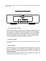
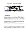
Operating instructions
For
MONO OUTPUT STAGE
TRETRE-50M
1
Preface
Short description
The output stage TRE-50M is a HiFi achievement amplifier for use in the home. The
output stage is constructed in mono technology, i.e. for a stereo application are
needed at least two devices.
The advantage over a power amplifier in stereo technology is that the output stages
can be set up close to the speaker and thus avoid long, expensive and loss-making
speaker cables. Furthermore results an unsurpassable channel separation, which
gains substantilly a spatial projection of the music.On principle each output stage has
of course their own power pack. Influences by a common use of the power pack are
therefore impossible. The 300VA strong power transformer and the more than
40000µF electrical capacity makes together sufficient energy available to supply the
output stage always in the intended capacity range with electricity and a stable
voltage.
The output stage has two entrances, which can be selected over a push-button on
the back of the device. Thereby is one entrance in asymmetrical technology (UNBAL)
and the other entrance in symmetrical technology (BAL) implemented.
Per a 3.5mm input jack the output stage can be activated remotely (AUTO) by a
control voltage (approx. 4-10V DC). This function is also selectable over a push
button attached on the back of the device.
The digital voltmeter on the front informs constantly about the actual level of the
mains voltage. This function can be switched on and off over a push-button on the
back of the output stage, too.
Useful is also the over-regulation announcement (PEAK), which calls your attention
to the fact that the output stage has arrived to its power limit and that a further
increase of the volume will lead to substantial distortions, this can harm your the
output stage and your speaker, too.
Start-up
Please arrange the output stages close to your speakers if it’s possible. Avoid direct
insolation or other heat sources in direct proximity of the output stages.
The output stages may be switched on only if all interwirings are manufactured. Make
sure that there is no short-circuit in the speakers conductor.
To avoid possible clicks of the preamplifier, you have to switch on at first always the
preamplifier and then the output stages.
And to switches off in the reverse order, i.e. you have to switch off at first the output
stages and then the preamplifier.
2
But it’s easier and safer if you use the automatic function (nearer information under
point 4, 10, 16)
The display on the front side
1
2
3
4
5
6
1. Three-figure digital voltmeter
This voltmeter indicates you the actual level of the mains voltage resting in the net
entrance socket. It can be switched on and/or off with the key 12 on the back of
the output stage. This display has an accuracy of approx.. 2%, i.e., fluctuations in
the last place around a digit are normal. This display is usefull for the qualitative
estimation of fluctuations of the mains voltages. You will soon find out at which
times of day this display stays relative constant, i.e. the mains voltage is stable
and sound falsifications by varying mains voltage is smallest.
2. LED display UNBAL
This display lights up, if you have selected the asymmetrical entrance (13) with
the key 11.
3. LED display BAL
This display lights up, if you have selected the symmetrical entrance (14) with the
key 11. Presupposed, your preamplifier has a symmetrical exit, should this
entrance be used whenever you use longer cables between preamplifiers and
output stage. Thus are external voltages, which can occur on a long cable run,
suppressed effectively.
Note: Usually a called 6dB level stroke would arose at the use of this entrance. To avoid a level
jump after switching to the asymmetrical entrance, we have asimilated the reinforcement of the
XLR entrance with the reinforcement of the Cinch entrance.
3
4. LED display AUTO ONE
This display lights up, if you have switched on the auto mode with the key 10.
Now the output stage automatically switches itself on, as soon as a control
voltage of 4 – 10 V is putting on over the socket 16.
You will appreciate this practical function soon, because now you haven’t to
activate each output stage separate for switching the output stages on and/or off.
5. LED display PROTECT
This display flashes, if dangerous DC voltage at the speaker exit were detected
by integrated protection electronics. If this display flashes, you should switch off
the output stage and after one minute you restart it. But if the display flashes
admittedly longer than a half minute, then a defect is present and you must bring
the output stage to the service.
Please have attention that this display flashes every time for approx. 15 seconds
after switching on, until all supply voltages and operating points have adjusted
themselves optimally. Afterwards the protect LED expired and the speaker relay is
switched on.
6. LED display PEAK.
Through strong dynamic jumps in the music it can come at times, depending from
the adjusted volume, to an lighting up of the PEAK-LED, but this is however
normal. Only if the display lights up more frequent, the volume at the preamplifier
have to be reduced, because now the power limit is reached. Reduce a little bit
the volume at the preamplifier, cause in the case of an over-regulation the tops of
the music signal become „amputated“. The consequence is that strong distortions
arises, whereby the high-pitched tones of the attached speaker can be damaged.
Usually an over-regulation is good hearable, so that these are fast noticed. Please
have a look at the PEAK-display from time to time to avoid a damage of your set if
there are large hearing volumes.
4
The connections and controls on the back
8
9
10 11 12
89
7
13
14
16
300
15
7. Net socket with fuse
Here the provided high-quality mains cable of the type TRIGON VOLT is put in.
Should there is the case that the fuse burned through, the mains cable has to be
pulled from the socket (and the wall socket). Now the safeguard subject can be
opened with a small screwdriver and a new fuse of same type can be used. But if
the fuse burns through immediately after switching on again, then the output
stage has to be send to the service.
Note: The name “fuse” is a bit confusing, because the fuse burns only through usually if an error
and/or a defect in the device arises, i.e. the fuse isn’t in this case for the security of the amplifier,
but rather for the avoidance of fire damage. Notice: The sequence is - at first the defect arises in
the output stage and that’s why the fuse burns through.
Without an fuse a defective device would be supplied further with electricity and damaged
construction units, from which the energy is not extracted, can catch fire fast. Please replace
burned through fuses only by fuses of same type!!!
8. Power switch.
This switch is the backbone network switch. If the output stage is not switched in
the auto mode (tracer 10), the output stage immediately switches on after
activating. If the output stage is in the auto mode (LED AUTO shines), the output
stage switches only after connecting the REMOTE control voltage.
5
9. Speaker exit
The speaker is attached to these clamps. Please make sure that the speaker
doesn’t fall below a minimum impedance of 2 Ohm. Make also sure that there is
no short-circuit at this socket no, so that the output stage doesn’t take a damage.
10. Key AUTO
With this key the automatic power up mode will be switched on and/or off. The
LED 4 on the front signals the auto mode.
11. Key BAL/UNBAL
With this key the symmetrical or asymmetrical entrance will be selected. The
display LED's 2 and 3 indicates each selected channel.
12. Key Display
With this key the digital mains voltage voltmeter can be switched on and/or off.
13. Cinch socket UNBAL INPUT
To this socket the asymmetrical exit of the preamplifier can be attached.
14. Cinch socket PRE-OUT INV
( Has no function.)
15. XLR – Input jack BAL INPUT
To this socket the symmetrical exit of the preamplifier can be attached.
6
16. REMOTE 10V DC
To this 3.5mm input jack the control voltage of 4-10V DC voltage (DC) will be
attached. If your preamplifier has a REMOTE exit, you can use the automatic
start-up function. It is like that, that if the preamplifier is switched on, a control
voltage of approx. 10V DC always rests against the remote sockets, which can be
used to switch on the output stages at the same time. Therefore increases this
function substantially the ease of use, because you haven’t switched on each
output stage individually.
Note: To avoid the so-called humming loops, you have to use only one wire for the setting up of a
control line and connect the contacts only at the cone point of the 3.5mm input jack. The return is
set up already over the signal lines (Cinch and/or XLR). The control cable hasn’t to be very thick,
because there is just a very low electricity flowing. It’s enough if you take a strand wire of the
strength 0,25 square millimetres.
An influence of the audio signal by the common use of the earth conductor is not given. Therefore
are sound influences not to be feared.
7
Technical data.
Power output
: 250 watt at 4 ohm, 135 watt at 8 ohm.
Entrances/input impedance
: 1x Cinch/47 kOhm, 1x XLR/47 kOhm.
Entrance sensitivity
: 1,2 Veff.
Distortion factor (THD + N)
: < 0.03%.
Frequency response
: 0,5 Hz – 200kHz -3dB.
Noise potential
unbal : 10µV (A-weighted) 14µV (unvalued).
bal : 15µV (A-weighted) 22µV (unvalued).
Distance of separate source voltage
: -103 dB related to 1 watt at 4 ohm.
Distance of weighted noise voltage
: -106 dB related to 1 watt at 4 ohm.
Weight
: 10.1 Kg
Dimensions
: 300 x 89 x 390 mm (b x h x t).
Subject to change.
Production and construction:
Trigon Elektronik GmbH
Crumbacher Str. 60
D-34277 Fuldabrück
Germany
Tel.: +49 (0) 561 - 20753880
FAX:+49 (0) 561 – 20753888
e-mail: [email protected]
web: www.trigon-audio.de
8