1
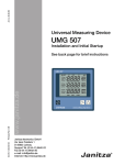
Universal Measuring Device UMG96L Operating Instructions Brief instructions see last page Mean value Programming mode Sum measurement Phase to phase L1-N / L1-L2 L2-N / L2-L3 L3-N / L3-L1 Dok Nr. 1.031.015.7 Peak value Password Voltage transformer Current transformer Minimum value Supply Key 1 Key 2 Table of contents The meaning of symbols Hints for the user Receipt control Contents of delivery Hints for maintenance Service 3 3 3 3 4 4 Product description 5 Intended use Functional description 5 5 Installation Mounting place Measuring and operating voltage Current measurement Sum current measurement Connecting options Putting into service 6 6 6 7 7 8 Indication mode Programming mode Key functions Table, measured value indication Current transformer Voltage transformer Averaging times Measured value indication Measured value rotation time Measured value selection Delete minimum and maximum values Delete energy Working hours counter LCD contrast Software Release User password Page 2 Safety guidelines Test voltage EMC requirements Technical data Ambient conditions Measurement Connectable cables Dimensions Connection example Brief instructions Change current transformer ratio Call up measured values 26 28 29 29 29 29 30 30 30 30 31 31 32 32 32 10 Installation 10 Attach measuring and operating voltage 10 Connect measuring current 11 Check phase assignment 11 Check current direction 11 Check measurement 11 Check phase power 11 Check sum power 11 Elimination of errors 12 Error messages 13 Usage and indication Uncertainty of measurement Configuration data Declaration of conformity 14 14 14 15 16 18 19 20 21 21 22 23 23 24 24 25 25 All rights reserved. No part of this manual may be reproduced or duplicated without the written permission of the author. Any contraventions are punishable and will be prosecuted with all legal means. No liability can be taken for the faultless condition of the manual or damage caused by the use of it. As failures cannot be avoided completely, we shall be very grateful for any advice. We are anxious to remove all failures as soon as possible. The mentioned software and hardware descriptions are registered trademarks in the most cases and are subject to the regulations by law. All registered trademarks are property of the corresponding companies and are fully recognized by us. Issue Note 13.01.04 First Edition. 15.04.04 Measurement uncertainly. 27.03.06 Page 10/12 marking voltage measurement. 11.01.07 Page 9, Abb.5, 6 and 8 been cancelled. 12.04.07 Storage temperature -25°C. The meaning of symbols Receipt control The symbols, which are used in this manual, have the following meaning: In order to ensure a perfect and safe use of the device, a proper transport, expert storage, erection and mounting and careful usage and maintenance is required. In case that a safe operation can no longer be granted, the device has to be put out of service and has to be protected against unintentional putting into service. A safe operation can no longer be assumed, if the device • shows visible damage, • does not work in spite of intact net supply, • has been exposed to disadvantageous conditions for a longer time (e.g. storage beyond allowed climate without adaption to the room climate, dew etc.) or transport use (e.g. falling from great height, even without visible damage). Ꮨ Beware of dangerous electrical voltage. symbol shall warn you about possi This ble danger, which can occur during installation, putting into service and usage. Hints for the user This device may be inserted and used by qualified personnel only according to the safety regulations. Please follow the legal and safety regulations for the corresponding application while using the device. Qualified personnel are persons, who are familiar with installation, mounting, putting into service and operation of the product and have qualifications according to their occupation, for example: - Education or instruction resp. the right to switch on or off, ground or characterize current circuits or devices according to the standards of safety techniques. - Education or instruction in care and use of safety equipment according to the standard safety techniques. Please test the contents of delivery for completion, before starting the installation of the device. Contents of delivery 1 pc. UMG96L, 2 pcs. fixing brackets, 1 pc. manual. As an option, a seal with part no. 29.01.907 can be delivered. All delivered options and versions are listed on the delivery papers. If the device is not used according to this Attention! manual, a safe use cannot be granted, and the instrument might cause danger. Ꮨ Attention! If a UMG 96L is installed in panels of metal, the panel must be earthed. manual also describes options, This which have not been delivered and do not belong to the contents of delivery. Page 3 Hints for maintenance Service Before delivery the device is tested in various safety checks and marked with a seal. If the device is opened, these checks must be repeated. For instruments, which are opened outside the manufacturing works, no warranty is granted whatsoever. If there are questions, which are not described in this manual, please contact us directly. For an efficient handling we need the following information: - Description of device (see type plate), - Serial digit (see type plate), - Software Release, - Measuring and operating voltage and - detailed description of error. Repairing and calibration Repairing and calibration work can be carried out in the manufacturing works only. Front foil The cleaning of the front foil has to be effected with a soft cloth using a common cleansing agent. Acid or acidic agents are not allowed for cleaning. Waste management The UMG96L can be disposed and recycled as electronical waste according to the legal regulations. Page 4 Product description Intended use Functional description The UMG96L is suitable for fix mounting and the measurement of voltage, current, power etc. in low voltage switchgear. The measurement is designed for 3 phase systems with neutral conductor (TN and TT-mains). The UMG96L is suitable for mounting in fix and weather protected panels. Conducting panels must be earthed. Due to the high resistance against interference, the UMG 96L is suitable for continous and unsupervised operation. The electronical three phase measurement system determines and digitalizes the effective values of voltages and currents in 50/60 Hz networks. The operating voltage for operation of UMG96L is generated by the measuring voltage L1-N. A random test measurement is carried out each second at all current and voltage inputs. Measuring signal interruptions, which last longer than one second are safely recognized. For each random test one period is scanned. From those sampled values the microprocessor calculates the electric quantities. These measured values are indicated within the programmable display. The energy as well as the minimum and maximum values are stored every 15 minutes whereas the programmed data are stored immedately is a none volatile memory (EEPROM). The scanning frequency for all measuring inputs is calculated from the net frequency of phase 1. At a net frequency of 50Hz the scanning frequency is 2,5kHz and for 60Hz it is 3,0kHz. L1 L2 L3 N 3M PE 3M The measuring and operating voltages must be connected to the UMG 96L via a separation (switch or power switch) and an overcurrent protection fuse (2-10A) in the building installation. The separation (switch or power switch) must be near the UMG 96L and easily accessible. 3M As the UMG96L receives its power from phase L1 of the measuring voltage, at least phase L1 and the neutral conductor N must be connected. The attached voltage must be within the range of the measuring and operation voltage shown on type plate. Either ../5A or ../1A current transformers can be connected to the current measuring inputs. The connection of the measuring and operating voltage is carried out on the back side of the UMG96L via all-insulated spring power clamps. Voltage measurement Generation of operating voltage UMG96L Diagr. Generation of the operating voltage from measurement voltage. Page 5 Installation Mounting place The UMG96L is suitable for a fix insertion into low and medium voltage switchgear. Any mounting position is possible. Measuring and operating voltage The operating voltage of the UMG96L is generated by the measuring voltage. The measurement is designed for three phase systems with neutral conductor (TN and TT mains). The measuring and operating voltages must be connected to the UMG 96L via a separation (switch or power switch) and an overcurrent protection (2-10A) within the building installation.The connection of the measuring and operating voltages is carried out at the back side of the UMG 96L via shock protected spring clamps. - The connection wires for the operating voltage leading to the UMG96L must be suitable for voltages up to 300V against ground. - The measuring and operating voltage has to be protected by a fuse, which must be in the range of 2A to 10A. - A switch or power switch for the operating voltage must be provided within the building installation. - The switch has to be near the instrument and easily accessible. - The switch must be marked as separation for this instrument. 230V/400V Standard version Phase L1 and the neutral conductor N must be connected, and the attached voltage must be within the range of the measuring and operating voltage. 120V/220V Special version Phase L1 and the neutral conductor N must be connected, and the attached voltage must be within the range of the measuring and operating voltage. 60V/110V Special version Phase L1 and the neutral conductor N must be connected, and the attached voltage must be within the range of the measuring and operating voltage. Ꮨ Page 6 Attention! The limits indicated in the technical data may not be exceeded, not even while checking and putting into service of the UMG 96L. Ꮨ Attention! Before the device is connected to voltage for the first time, it should be deposited the installation room for at least 2 hours, to create a temperature assimilation and avoid condensation and dew. Current measurement Sum current measurement The current measurement is carried out via ../ 5A or ../1A current transformers. In case that the current has to be measured by an Amperemeter in addition to the UMG96L, the Amperemeter has to be connected in series to the UMG96L. In mains with voltage up to 300VAC against ground, currents up to 5A can be connected and measured directly to the UMG 96L. If the current measurement is carried out via two current transformers, the total transformer ratio must be set to the UMG96L. Verbraucher Consumer Example: Sum current transformer A current measurement is carried out via one current transformer with a ratio of 1000/5A and another one with a ratio of 200/5A. The sum measurement is carried out with a sum transformer 5+5/5A. The UMG96L has to be programmed as follows: l L l UMG96L K k A k Einspeisung Supply Diagr. Connection example: UMG96L with Amperemeter in series. Inaccuracy The inaccuracy of the current measuring input is +- 1% of the measuring range (5A). Therefore, the inaccuracy of the current measurement is +-50mA. Example: Inaccuracy With a current transformer 200/5A, the measuring range is 200A. The inaccuracy is +-1% of 200A = +-2A. Resolution The maximum resolution of the current measuring inputs is 10mA. The indication changes in 0.01A steps. Example: Resolution current transformer 200/ 5A With a current transformer ratio of 200/5A, a resolution of 10mA*40 = 400mA is effected. The display changes in 0.4A steps. Small currents The minimum working current is 20mA. At short circuited or open current measurement input, the UMG 96L can indicate a small current. This current is within the range of the allowed measurement inaccuracy. Primary current: Secondary current: 1000A + 200A = 1200A 5A Verbraucher 1 Consumer 1 Verbraucher 1 Consumer 1 L l K k L l K k AK AL BK Bl Einspeisung 1 Supply 1 K l k l UMG96L Einspeisung 1 Supply 1 Ꮨ Attention! Current transformers may not be han- dled in open condition of the secondary, as the secondary clamps can lead live voltage. Ꮨ Attention! Prior to connecting or exchanging the UMG 96L, the secondary clamps of the external current transformers have to be short circuited. The program allows current and voltage Attention! transformer ratio setting only, if the maximum phase power can reach up to 50.0MW and the sum power can reach a maximum value of 150.0MW. Page 7 Connecting options UMG96L UMG96L Voltage MeasureCurrent ment measurement see type plate 0,02 .. 5A k L1 L2 L3 N l l ../5(1)A k l ../5(1)A k ../5(1)A Diagr.: Connection example 1 Four wire measurement with three current transformers 1 2 3 4 5 6 7 8 9 10 L1 L2 L3 N 1k 1l 2k 2l 3k 3l 5 6 7 8 9 10 1k 1l 2k 2l 3k 3l x x x X X X l Verbraucher Consumer k l ../5(1)A k l ../5(1)A k ../5(1)A Diagr.: Connection example 3 Measurement with three voltage transformers and three current transformers. Page 8 l u u u x x x X X X U U U k ../5(1)A Diagr: Connection example 2. Four wire measurement with two current transformers. u u u L1 L2 L3 PEN l ../5(1)A Voltage MeasureCurrent ment measurement see type plate 0,02 .. 5A Voltage MeasureCurrent ment measurement see type plate 0,02 .. 5A L1 L2 L3 N k L1 L2 L3 PEN UMG96L UMG96L 1 2 3 4 5 6 7 8 9 10 1k 1l 2k 2l 3k 3l L1 L2 L3 PEN U U U k l ../5(1)A k ../5(1)A l Verbraucher Consumer L1 L2 L3 PEN 1 2 3 4 5 6 7 8 9 10 1k 1l 2k 2l 3k 3l Verbraucher Consumer 1 2 3 4 L1 L2 L3 N Verbraucher Consumer Voltage MeasureCurrent ment measurement see type plate 0,02 .. 5A Diagr.: Connection example 4 Measurement with three voltage transformers and two current transformers. UMG96L 1 2 3 4 L1 L2 L3 N L1 L2 L3 N Current measurement 0,02 .. 5A 5 6 7 8 9 10 1k 1l 2k 2l 3k 3l k l l ../5(1)A k l ../5(1)A k ../5(1)A Verbraucher Consumer Voltage Measurement see type plate PE Diagr.: Connection example 7 Measurement in IT networks via three current transformers. Page 9 Putting into service The putting into service of the UMG 96L should be carried out as follows: Installation The UMG96L is designed for mounting in low voltage distributions, which contain overvoltage in measurement category III. The UMG96L is suitable for installation in fixed and weather proof panels. Conducting panels must be earthed. Any mounting position is possible. For mounting on front panels or doors, the delivered fixing brackets have to be used. 123 123 123 123 123 123 123 123 123 123 123 123 123 123 123 123 123 123 123 123 123 123 123 123 123 123 123 123 123 123 42 Diagr. Side view Attention! do not correspond to the indication on the type plate, can lead to malfunction and damage of the instrument. The connection wires for measuring voltage leading to the UMG96L must be suitable for voltages up to 300V against ground and 520V phase to phase. After connecting the stated measuring and operating voltage to the UMG 96L, all segments of the display appear. After approx. two seconds, the UMG 96L switches to the first measured value indication. In case that no indication appears, please check, if the attached operating voltage is within the rated voltage range. Made in Germany IP20 S V J M A D E P UMG96L 45-65Hz 2,5VA 90 Fixing brackets Ꮨ Mesuring and operating voltage, which 96 Panel max. 6123 Attach measuring and operating voltage The allowed measuring and operating voltage of UMG 96L is indicated on the type plate. 4 3 N 1 2 L3 L2 L1 210A Spannungsmessung Voltage Measurement 6 Strommessung/Current Measurement L1 L2 L3 k 5 l 6 k 7 l 8 k l 9 10 Program current and voltage transformers When the device leaves the manufacturer, a current transformer of 5/5A is set. The set voltage transformer ratio has to be changed only, if a voltage transformer is connected. When connecting voltage transformers, please observe the allowed measuring and operating voltage stated on type plate! Page 10 Connect measuring current The UMG96L is designed for the connection of ../1A and ../5A current transformers. With the current inputs, only alternating current but no direct current can be measured. Ꮨ Current transformers may not be hanAttention! dled in open condition, as there might be live voltage at the secondaries. Made in Germany IP20 UMG96L 45-65Hz 2,5VA S V J M A D E P Please connect the current inputs one after the other, and compare the indicated current of the display with the actual current. Please note, that the current transformer ratio is set to 5/5A and has to be adapted to the existing current transformers. In case that the current transformer is short circuited on the secondary, the indicated current at the corresponding conductor at UMG 96L has to decrease to a value, that corresponds to the secondary current plus tolerance. The current indicated by UMG 96L, has to conform to the input current, under consideration of the current transformer and tolerance. 4 3 N 1 2 L3 L2 L1 210A Spannungsmessung Voltage Measurement Strommessung/Current Measurement L1 L2 L3 k 5 l 6 k 7 l 8 k l Check current direction Short circuit two current transformers on the secondary. The real power in the connected phase has to be: Positive (+) for consumption of real power and negative (-) for supply of real power (power station service). In case that no real power is indicated, the assignment of voltages and currents may be wrong. Check measurement Provided that all voltage and current inputs are connected correctly, the phase and sum power is calculated and displayed correctly. Check phase power In case that a current transformer is assigned to the wrong outer conductor, the corresponding power is measured and indicated incorrectly. The assignment of the outer conductor and current transformer is correct, if no voltage is measured between the outer conductor and the primary of the corresponding current transformer. To ensure that the outer conductor at the voltage input is assigned to the right current transformer, please short circuit the secondary of the corresponding current transformer. The apparent power of this phase at UMG 96L must be indicated by zero. If the apparent power is indicated correctly, but the real power has a „-“ sign, the current transformer clamps are interchanged, or power is supplied to the energy supplier. 9 10 Check phase assignment The assignment of the outer conductors to the current transformer is correct, if a current transformer is short circuited on the secondary, and the indicated current in the corresponding phase decreases to a value at the UMG96L, which corresponds to the secondary current plus tolerance. Check sum power Provided that all voltage, current and power in the corresponding phase is indicated correctly, the sum power must be displayed correctly by UMG 96L either. For verification, the sum power measured by UMG96L should be compared to the energy stated by the real and reactive energy counters of the supplier. Page 11 Elimination of errors Error Reason Elimination Display dark. Prefuse released. Device defective. Insert fuse. Send the device to the producer for repair. Measured value can- The indication has been deleted from measured value senot be called up. lection. Add the required measured value indication to the measured value selection. No current indication. Corresponding voltage is not connected. Connect corresponding voltage. Current too small. Current measurement in wrong phase Check and correct connection. Current incorrect. Current measurement in wrong phase Current transformer programmed incorrectly. Measuring range exceeded. Check and correct connection. The current peak at measuring input was exceeded caused by harmonic waves. Insert a current transformer with a higher ratio. Attention! Please ensure, that the measuring inputs are not overloaded. Insert a current transformer with a smaller ratio. Check and correct connection. The current at measuring input was below measuring range. Read ratio of current transformer and program accordingly. Insert a current transformer with a higher ratio. Voltage L-N incor- Measurement in wrong phase. rect. Voltage transformer ratio programmed incorrectly. Check and correct connection. conductors Voltage L-L too small Phase changed. / too high. Check and correct connection. Page 12 inter- Read the voltage transformer ratio at the voltage transformer and program accordingly. N not connected. Check and correct connection. Voltage transformer ratio programmed incorrectly. Read voltage transformer ratio at the voltage transformer and program accordingly. Error Reason Elimination Phase shift ind/cap. Current path is assigned to the wrong voltage path. Check and correct connection. data The device was exposed to electro magnetical disturbance, which was higher than those mentioned in the technical data. Improve external protection measures such as protection, filtering, earthing and local separation. Real power too small Current transformer ratio is programmed incorrectly. / too high. Current path is assigned to the wrong voltage path. Read current transformer ratio and program accordingly. Check and correct connection. Real power supply / At least one current transconsumption inter- former connection is interchanged. changed. Current path is assigned to the wrong voltage path. Check and correct connection. Programmed get lost. „Err“ in display. Check and correct connection. See „error messages“ The device does not Device defective. operate in spite of the above. Please send the device back to the producer with a detailed description of the error. Error messages While exceeding an allowed measured value range, the UMG 96L indicates the error message „Err“. An exceeding of a measured value range arises, if at least one of the three existing current or voltage inputs or the frequency is out of the specified measuring range. The symbols "V", "A" and „Hz“ indicate, which measured value is out of range. The phase is marked by the arrows upwards in which the exceeding occured. A = Current path V = Voltage path Hz = Frequency L1 VA Hz L2 L3 Exceeding of measuring range in phase L1/L2/L3 Attention! Voltage and current beyond the specifications may destroy the device. Page 13 Usage and indication The usage of the UMG96L is carried out via the keys one and two. Measured values and programming data are indicated on the liquid crystal display. You must distinguish between Indication mode and Programming mode. By entering a password, you can avoid unintentional change of programming data. Indication mode In indication mode please scroll through the programmed measured value indications by using the keys 1 and 2. When the device is delivered, you can call up all measured values shown in table 1. For each measured value indication, up to three measured values are indicated. The measured value rotation allows to indicate all selected measured values on an alternate basis with a selectable changing time. Programming mode cap L1 cos ϕ ind PRG MkWh MkVArh cap L2 cos ϕ ind Hz S cap L3 cos ϕ ind CT VT K1 K2 L-L 1 Key1 2 Key 2 Programming mode In programming mode the settings, which are necessary for the operation of the UMG96L, can be indicated and changed. Pressing the keys 1 and 2 simultaneously for about 1 second, you reach programming mode via the password indication. If no user password is programmed, you reach the first programming menu directly. The programming mode is marked with the text „PRG“ in the display. With key 2 you can shift between the programming menues. If you are in the programming mode and no keys are pressed for 60 seconds, or you press the keys 1 or 2 simultaneously for approx. 1 second, you return to the indication mode. Page 14 Programming menus: - Current transformer, - Voltage transformer, - Averaging times, Measured value indications - Changing time, - Measured value selection, - Measured value rotation, - Delete minimum and peak values, - Delete energy, - LCD contrast, - Software Release, - User pasword. Key functions Programming mode Password Indication mode simultaneous Change mode 1 2 simultaneous Measured values 2 Programming menu long long 1 2 Programming menu Measured values Measured values long Measured values 1 short short Scroll 2 Programming menu short Programming Programming menu 1 Confirm selection 2 short digit +1 long digit -1 2 short value *10 (decimal point to the right) 2 flashing long value /10 (decimal point to the left) Page 15 Table, measured value indication Measured values L1-N Voltage L2-N Voltage L3-N Voltage Maximum values L1-N Voltage L2-N Voltage L3-N Voltage Minimum values L1-N Voltage L2-N Voltage L3-N Voltage Measured values L1-L2 Voltage L2-L3 Voltage L3-L1 Voltage Maximum values L1 Real power L2 Real power L3 Real power Minimum values L1 Real power L2 Real power L3 Real power Measured values L1 Current L2 Current L3 Current Mean values L1 Current L2 Current L3 Current Maximum values L1 Current L2 Current L3 Current Max. values L1 Curr. mean val. L2 Curr. mean val. L3 Curr. mean val. Measured value Σ Current in N Mean value Σ Current in N Maximum value Σ Measured value current in N Maximum values Σ Mean value current in N Measured values L1 Real power L2 Real power L3 Real power Mean values L1 Real power L2 Real power L3 Real power Maximum values L1 Real power L2 Real power L3 Real power Measured value sum real power Mean value sum real power Maximum value (Consumption) sum real power meas. Measured values L1 Apparent power L2 Apparent power L3 Apparent power Mean values L1 Apparent power L2 Apparent power L3 Apparent power Maximum values L1 Apparent power L2 Apparent power L3 Apparent power Measured value sum apparent power Mean value sum apparent power Maximum value sum meas. value apparent power Page 16 Maximum value (Consumption) sum real power, mean Measured values L1 Reactive power L2 Reactive power L3 Reactive power Mean values L1 Reactive power L2 Reactive power L3 Reactive power Max. values (ind) L1 Reac. power L2 Reac. power L3 Reac. power Measured value Sum reactive power Mean value Sum reactive power Max. value (ind) Sum reactive power Measured value L1 cos(phi) L2 cos(phi) L3 cos(phi) Measured value Sum cos(phi) Measured value L1 Frequency Measured value (Consumption) Sum real energy Measured value Sum reactive energy(ind) Working hours counter Page 17 Current transformer Current transformers with either 1A or 5A secondary can be connected to the UMG96L. A transformer ratio of 5A/5A is preset by the manufacturer. In programming mode the current transformer setting is marked by the symbol „CT“. Programming In programming mode please scroll to the current transformer ratio by pressing key 2. Confirm the selection by pressing key 1. The first digit of the primary current flashes and can be changed by pressing key 2. If key 1 pressed again the next digit will be selected and flashes now. If the entire digit flashes, the decimal point can be moved. Press key 2 shortly - The decimal point moves to the right. Press key 2 longer - The decimal point moves to the left. If no digit flashes anymore, you can shift to the indication of the voltage transformer. Primary (5.00kA = 5000A) PRG L1 k A L2 CT L3 Secondary Current transformer symbol Example: Sum current transformer A current measurement is carried out via two current transformers, one with a ratio of 1000/ 5A and another transformer with a ratio of 200/ 5A. The sum measurement is carried out with a sum current transformer 5+5/5A. The UMG96L has to be programmed with the following values: Primary current: 1000A + 200A = 1200A Secondary current: 5A Attention! The program allows current and voltage transformer ratio setting only, if the maximum phase power can reach up to 50.0MW and the sum power can reach a maximum value of 150.0MW. Page 18 Voltage transformer The phase to phase voltage (L-L) is indicated on display of the UMG 96L as secondary and primary voltage. The transformer ratio is calculated from the programmed primary and secondary voltage. In programming mode, the voltage transformer settings are marked by the symbol „VT“. The standard version is preset by the manufacturer with a ratio of 400V/400V. The secondary voltage is always indicated in „V“. The corresponding symbol „V“ is not displayed. The primary voltage is indicated in „V“ or „kV“. The corresponding symbol is displayed in „V“ or „kV“. UMG96L Version Type plate Standard version Special version Special version 196 .. 255V 90 .. 160V 45 .. 80V Programming In programming mode, please scroll to the voltage transformer setting by pressing key 2. Confirm selection with key 1. Primary voltage PRG L1 V L2 L-L VT L3 Secondary voltage Phase to phase Voltage transformer ratio Setting range voltage transformer L-L secondary L-L primary 400V 200V, 220V 100V, 110V 100V .. 60kV (400V) 100V .. 60kV (200V) 100V .. 60kV (100V) Primary voltage is 10,0kV PRG L1 The first digit of the primary voltage flashes and can be changed by pressing key 2. If key 1 is pressed again the next digit will be selected and flashes. If the entire digit flashes, you can move the decimal point. If no digit flashes anymore, you may shift to indication and programming of the outputs by pressing key 2. kV L2 L-L VT L3 Secondary voltage is 100V Example: Voltage transformer ratio 100V/10kV The program allows current and voltage Attention! transformer ratio setting only, if the maximum phase power can reach up to 50.0MW and the sum power can reach a maximum value of 150.0MW. Page 19 Averaging times A mean value is calculated for the most at the current and power values. A common averaging time for the current measured values L1, L2, L3 and N , as well as one for power measured values, real power, apparent power and reactive power is programmable. Method of taking the mean The used exponential method reaches at least 95% of the measured value after the set averaging time. Presettings: Averaging time of currents = 900 seconds Averaging time of power = 900 seconds MEn MA n N The following averaging times are selectable: 5, 10, 30, 60, 300, 480, 900 seconds MEn = MEn-1 + (MA-MEn-1) / N = indicated mean value = measured value = consecutive digit = digit of measured values, of witch mean values shall be built. Programming of averaging time Averaging time for real power In programming mode please scroll to the averaging time for power with key 2. Confirm selection by pressing key 1. The averaging time flashes and can be changed by pressing key 2. Confirm changed averaging time with key 1. The averaging time stops flashing. The averaging time for power has been programmed. By using key 2 you can now shift to programming menu „Averaging time for current“. Averaging time for Currents In programming menu please scroll to the averaging time for currents. Confirm selection by pressing key 1. The averaging time flashes and can be changed by pressing key 2. Confirm changed averaging time with key 1. The averaging time stops flashing. The averaging time for currents has been programmed. By using key 2 you can now shift to programming menu „Rotation time“. Page 20 L1 PRG W L2 S L3 Example for the averaging time of real power mean value, here 900 seconds. L1 L2 PRG PRG MkWh A MkVArh S L3 Example for the averaging time of current mean value, here 30 seconds. Measured value indication Once in a second all measured values are calculated and can be indicated on the display. Two methods are available for calling up the measured value indications (see table 1). - The selection of measured value indications via the keys 1 and 2, herein called measured value selection. - The automatically rotating indications of selected measured value indications, herein called measured value rotation. A measured value rotation time has be programmed additionally for the measured value rotation. All mesured values for the measured value selection are preset by the manufactures. For the automatic rotation nothing is preset by the manufacturer. The rotation time is preset with 0 seconds. Measured value rotation time Both methods are available simultaneously. The measured value rotation is programmed, if at least one measured value indication and one measured value rotation time bigger than 0 seconds is programmed. If no key is pressed for about 60 seconds, an automatical change to rotation mode will be carried out, and all programmed measured values will be indicated one after the other. Setting range of measured value rotation time: 0 .. 250 seconds If 0 seconds are programmed, no rotation will be carried out. Nevertheless, measured value indications which are not programmed in the measured value selection, can be used for measured value rotation. Rotation time in seconds indicated PRG L1 L2 S L3 Abb. Programming In programming mode please scroll to the menu measured value rotation, by using key 2. Confirm selection with key 1. The first digit of the rotation time flashes and can be changed by pressing key 2. By pressing key 1 again the next digit will be selected and flashes. If no digit flashes anymore, you can shift to programming menu „Measured value selection“ by pressing key 2. Page 21 Measured value selection All measured values stated in table 1 (see page 16 and 17) can either be displayed via keep 1 and 2 measured value selection or automatically measured value rotation. All measured values for the measured value selection are preset by the manufakturer. For the automatical measured value rotation nothing is preset by the manufakturer. The condition of the selection is indicated by the output symbols. These symbols have the following meaning: PRG L1 L2 L3 Measured value selection K1 The indication can be reached via the keys. K1 The indication cannot be reached via keys. Measured value rotation K2 The indication changes automatically. K2 The indication does not change automatically. Programming In programming mode please scroll to programming menu mesured value indication by pressing key 2. Confirm selection by pressing key 1. The first measured value indicated stated in table 1 (see page 16 and 17) occurs. A selection of the measured value indication is carried out by pressing the keys quickly. Key 1 - Scroll to the right within the measured value indications. Key 2 - Scroll downwards within the measured value indications. Measured value indication of the current values PRG L1 A L2 L3 For the selected measured value indication, it can now be determined whether it will be available for measured value selection and for automatic rotation. The selection is carried out by an extended push on keys 1 or 2. Key 1 - Measured value selection. Key 2 - Automatic rotation. Once the programming is finished, you return to indication mode by pressing keys 1 and 2 simultaneously. Page 22 K1 K2 Measured value selection Measured value rotation Delete minimum and maximum values In programming mode, „Deletion of minimum and maximum values“ is marked by arrows upwards and downwards. All minimum and maximum values will be deleted simultaneously in menu „Deletion of minimum and maximum values“. An exception is the maximum value of the current mean value. The maximum value of the current mean value can also be deleted directly in indication menu by an extended pressing of key 2. Delete In programming mode please scroll to “Deletion of minimum and maximum values” by pressing key 2. With key 1 you can shift between the indicated digits 0 and 1. These digits have the following meaning: 0 = Minimum and maximum values not to be deleted. 1 = Minimum and maximum values to be deleted. PRG L1 L2 L3 PRG L1 L2 L3 Leave menu “Deletion of minimum and maximum values” by pressing key 2. In case that digit 1 was displayed, all minimum and maximum values were deleted. Delete energy The real and reactive energy can only be deleted together via the keys. L1 PRG Wh L2 L3 Delete In programming mode please scroll to the menu “delete energy” by using key 2. By pressing key 1 you can shift between digits 0 and 1. These digits have the following meaning: 0 = Real and reactive energy not to be deleted. 1 = Real and reactive energy to be deleted. Leave menu “Delete energy” by pressing key 2. In case that digit 1 was displayed real and reaktive energy were deleted. L1 PRG Wh L2 L3 Page 23 Working hours counter The working hours counter detects the time, in which the UMG96L measures and indicates data. The time is measured with a resolution of 15 minutes and is indicated in hours. The working hours counter cannot be deleted. L1 h L2 L3 Display example: The UMG96L indicates 40201 working hours. LCD contrast The favoured view for the LCD display is from below. The LCD contrast of the LCD display can be adapted by the user. The contrast setting is possible in the range from 0 to 7. 0 = very light 7 = very dark Programming In programming mode please scroll to LCD contrast by pressing key 2. Confirm selection with key 1. PRG L1 L2 L3 PRG The first digit of the contrast setting is flashing. Move to the right digit with key 1. Now you can change the digit with key 2. Afterwards you can shift to programming menu „user password“ by pressing key 2. L1 L2 L3 Page 24 Software Release The internal software of the UMG96L will be improved and extended continuously. The software update is registered in the device by a specific number the so called software release. The software release cannot be changed by the user. PRG L1 L2 L3 Example: In UMG96L, the software release 1.23 is installed. User password A user password can be programmed in order to avoid an unintentional change of programming data. Only after entering the correct password, a shifting into the following programming menues possible. No user password by the manufacturer is preset (000). In this case, the password menu will be skipped and you reach the current transformer menu directly. In case that a user password was programmed, a „000“ appears in the display of the password menu. The first digit of the password menu flashes and can be changed with key 2. By pressing key 1, the next digit will be selected and flashes. Only after the correct password was entered, you reach the programming menu for the current transformer. In case that a changed password is not known anymore, the device must be sent back to the manufacturer. PRG L1 L2 L3 User password Page 25 Uncertainty of measurement Quantity Indicating range Measuring range1) Measurement uncertainly2) Auxiliary voltage5) 196..255V Voltage L-N Voltage L-L Current Current in N Real power, consumption, sum Real power, supply, sum Apparent power, sum Reactive power (Q0), sum 0 .. 34kV 0 .. 60kV 0,00 .. 9,99kA 0,00 .. 9,99kA 0,00W .. 150MW -0,00W .. -150MW 0,00VA .. 150MVA 0,00var .. 150Mvar 50 .. 255V 87 .. 442V 0,02 .. 6,00A 0,06 .. 18,00A 3,9W .. 3,825kW -3,9W .. -3,825kW 3,9VA .. 3,825kVA 3,9var .. 3,825kvar +-1,5% +-2,0% +-1,0% +-3,0% +-1,5% +-1,5% +-1,5% +-1,5% rng rng rng rng rng rng rng rng Auxiliary voltage5) 90 .. 160V Voltage L-N Voltage L-L Current Current in N Real power, consumption, sum Real power, supply, sum Apparent power, sum Reactive power (Q0), sum 0 .. 34kV 0 .. 60kV 0,00 .. 9,99kA 0,00 .. 9,99kA 0,00W .. 150MW -0,00W .. -150MW 0,00VA .. 150MVA 0,00var .. 150Mvar 25 .. 160V 45 .. 277V 0,02 .. 6,00A 0,06 .. 18,00A 1,8W .. 2,4kW -1,8W .. -2,4kW 1,8VA .. 2,4kVA 1,8var .. 2,4kvar +-1,5% +-2,0% +-1,0% +-3,0% +-1,5% +-1,5% +-1,5% +-1,5% rng rng rng rng rng rng rng rng Auxiliary voltage5) 45 .. 80V Voltage L-N Voltage L-L Current Current in N Real power, consumption, sum Real power, supply, sum Apparent power, sum Reactive power (Q0), sum 0 .. 34kV 0 .. 60kV 0,00 .. 9,99kA 0,00 .. 9,99kA 0,00W .. 150MW -0,00W .. -150MW 0,00VA .. 150MVA 0,00var .. 150Mvar 16 .. 80V 28 .. 139V 0,02 .. 6,00A 0,06 .. 18,00A 0,9W .. 1,2kW -0,9W .. -1,2kW 0,9VA .. 1,2kVA 0,9var .. 1,2kvar +-1,5% +-2,0% +-1,0% +-3,0% +-1,5% +-1,5% +-1,5% +-1,5% rng rng rng rng rng rng rng rng cos(phi) Frequency (of voltage) Reactive energy, inductive v6) < 10 v6) < 100 v6) >= 100 Real energy, consumption v6) < 10 v6) < 100 v6) >= 100 Working hours counter 3) 0,00i .. 1.00 .. 0,00c 45,0 .. 65,0Hz +-1,5% rdg 0..999 999 9.99kvarh 0..999 999 99.9kvarh 0..999 999 999kvarh class 24) class 24) class 24) 0..999 0..999 0..999 0..999 class 24) class 24) class 24) +-2Min./Day 999 999 999 999 9.99kWh 99.9kWh 999kWh 999h The program allows current and voltage transformer ratio setting only, if the maximum phase Attention! power can reach up to 50.0MW and the sum power can reach a maximum value of 150.0MW. Page 26 These specifications presuppose a yearly calibration and a warm up time of 10 minutes. Used abbreviations: rng = of measuring range rdg = of measured value 1) Measuring range with scale factor = 1, (Current tranformer = 5/5A, 1/1A) In the range of -10..18°C and 28..55°C, an additional error of +-0,5‰ of measured value has to be considered per K. 3) If the measured apparent power is in the range of 1% .. 100% of the measuring range, cos(phi) is indicated with an accuracy of +-3%. 4) Accuracy class according to DIN EN61036:2001-01, VDE0418part 7, IEC61036:1996 + A1:2000 5) The auxiliary voltage is taken from the measuring voltage. 6) The maximum indication range and the resolution of real and reactive energy depends on Transformer ratio v = vi * vu. vi = Transformer ratio of current transformer. vu = Transformer ratio of voltage transformer. 2) Example: 200/5A -> vi = 40 1000/100V -> vu = 10 v = vi * vu v = 40 *10 v = 400 Indication range and resolution for real and reactive energy Energy /kvarh /kWh 999.999.999 210.000.000 21.000.000,0 2.100.000,00 1 10 100 400 v Transformer ratio v Page 27 Configuration data Description Current transf., primary Current transf., secondary Voltage transf., primary Type plate, 196 .. 255V Type plate, 90 .. 160V Type plate, 45 .. 80V Voltage transformer, sec. Type plate, 196.. 255V Type plate, 90 .. 160V Type plate, 45 .. 80V Averaging time, current Averaging time, power Measured value rotation Measured value selection LCD contrast Software Release User passwort Working hours counter Page 28 Display Setting range Presettings CT CT 1A .. 10,0kA 1A, 5A 5A 5A VT VT VT 100V .. 60.0kV 100V .. 60.0kV 100V .. 60.0kV 400V 200V 100V VT VT VT 400V (not changeable) 200V, 220V 100V, 110V 5, 10, .. 900Sec. 5, 10, .. 900Sec. 0 .. 250 seconds All indications 0 .. 7 not changeable 000 .. 999 not changeable 400V 200V 100V 900Sec. 900Sec. 0 = no rotation all indications 3 x.xx „000“ = no password 0h Declaration of conformity The UMG96L fulfills the protection guidelines of: Guideline 89/336/EWG in combination with DIN EN61326 (2002-03) as well as Guideline 73/23/EWG and 93/68/EWG in combination with EN 61010-1 (2002-08) Safety guidelines Safety requirements for electrical equipment for measurement, control, and laboratory use Part1: General requirements : EN61010-1:2001, IEC 61010-1:2001 Test voltage Enclosure against measuring inputs : 2kV AC Between the inputs for measuring and auxiliary voltage and the current inputs exists a functional separation of 2000V AC. EMC requirements Electromagnetic emission Electromagnetic immunity Enclosure AC-power line Current transformer inputs : DIN EN61326:2002-03, table 4, class B : DIN EN61326:2002-03, table A.1 : ESD test, IEC61000-4-2:2001 (4kV/8kV) : Electromagnetic RF-field, IEC61000-4-3:2002 (10V/m) : Netfrequent magnetic field, IEC61000-4-8:2000 (120A/m) : AC-Power variation and dropout, IEC61000-4-11:2000 : Fast transients (Burst), IEC61000-4-4:2001 (2kV) : Powerful pulse (Surge), IEC61000-4-5:2000 (1kV L- N) : RF induced on lines, IEC61000-4-6:2000 (3V) : Fast transients (Burst), IEC61000-4-4:2001 (2kV) : Powerful pulse (Surge), IEC61000-4-5:2000 (1kV) : RF induced on lines, IEC61000-4-6:2000 (3V) Page 29 Technical data Weight Calorific value : 250g : 2,2MJ (610Wh) Ambient conditions Measurement category Pollution degree Protection class Ambient temperature Storage temperature Humidity Protection class Front Front with seal (Option) Back side Mounting position Operating height : : : : : : III (Measurement within building installation) 2 II = with protective earth -10°C .. +55°C -25°C .. +70°C 15% up to 95% without dew : : : : : IP50 according to IEC60529 IP65 according to IEC60529 IP20 according to IEC60529 random 0 .. 2000m over sea level : : : : : : : : 1 measurement per second 4kV 45Hz .. 1000Hz 2,5kHz/3,0kHz (Net frequency 50Hz/60Hz) see type plate 2A .. 10A (medium time lag type) 45Hz .. 65Hz ca. 0,1VA per phase. Measurement Measuring inputs Measuring rate Rated pulse voltage Signal frequency Scanning frequency Measuring and operating voltage Fuse Frequency of fundamental Power consumption Phase (L-N) 230V/400V Standard version operating voltage Range 120V/220V Special version operating voltage Range 60V/120V Special version operating voltage Range Current measurement Power consumption Rated current at ../5A (../1A) Minimum working current Current limit at ../1A Current limit at ../5A Overload Accuracy class of energy measurement : 196 .. 255V AC : L-N 50V .. 255V, L-L 86V .. 442V : 90 .. 160V AC : L-N 25V .. 160V, L-L 45V .. 277V : 45 .. 80V AC : L-N 16V .. 80V, L-L 28V .. 139V : : : : : : : approx. 0,2VA 5A (1A) 20mA 1,2A (sinus shape) 6A (sinus shape) 150A for 2 Sec. class 2 Connectable cables One wire, multiple-wire, fine wire Pin contacts Page 30 : 0,08 - 2,5mm2 : 1,5mm2, only one conductor may be connected per terminal! Dimensions Cut out: 92+0,8 x 92+0,8 mm 123 123 123 123 123 123 123 123 123 123 123 123 123 123 123 123 123 123 123 123 123 123 123 123 123 123 123 123 123 123 123 42 Made in Germany IP20 UMG96L 45-65Hz 2,5VA 4 3 N L3 1 2 L2 L1 210A Spannungsmessung Voltage Measurement Type plate 96 90 Fixing angles S V J M A D E P Panel max. 6123 Strommessung/Current Measurement L1 L2 L3 k k k l l l 5 6 7 8 9 10 6 Diagr. Side view Diagr. Back view All dimensions in mm Connection example UMG96L Voltage MeasureCurrent ment measurement see type plate 0,02 .. 5A L1 L2 L3 N L1 L2 L3 PEN 5 6 7 8 9 10 1k 1l 2k 2l 3k 3l k l l ../5(1)A k l ../5(1)A k ../5(1)A Verbraucher Consumer 1 2 3 4 Diagr.: Connection example 1 Four wire measurement with three current transformers. Page 31 Brief instructions Change current transformer ratio Programming mode Shift to programming mode If you are in the indication mode please press the keys 1 and 2 simultaneously for approx. 1 second. Now you reach programming mode. The symbols for programming mode PRG and for the current transformer CT appear. Confirm selection with key 1. The first digit of the primary flashes. Change primary current: Change the flashing digit with key 2. Select the next digit to be changed by pressing key 1. The selected digit flashes. If the entire number flashes, the decimal point can be moved. PRG L1 k A L2 CT L3 Current transformer symbol 1 2 Primary current PRG L1 k A Change secondary current: Only 1A or 5A can be set as secondary current. Select secondary current with key 1. Change flashing digit with key 2. L2 CT L3 Leave programming mode: Press both keys simultaneously for approx. 1 second. The current transformer setting will be stored and you return to indication mode. Secondary current 1 2 Call up measured values Shift to indication mode If you are in programming mode please press the keys 1 and 2 simultaneously for approx. 1 second. Now you reach the indication mode. The symbol PRG for programming mode does not appear in the display and the first measured value indication, e.g. for the voltage appears. Key 2 With key 2 you scroll between the different measured value indications for current, voltage, power etc. Key 1 With key 1 you scroll between the mean values, maximum values etc., related to the corresponding measured value. Page 32 L1 V L2 L3 1 2