1
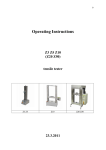
Operating Instructions
Tensile Testers
Z3, Z5, Z10, Z20, Z50
Z3 Z5
Z10
Z20 Z50
1/2015
1
Table of Content
1:
2:
3:
4:
5
6:
7:
Introduction
Checking Contents and the Number of Machine
Power on checks
Control Display Unit
Menue Keypad
Configuration
Load Cell
8:
9
10
11:
12
13
14
15
Interface USB
Upload Hex file
Special Programs
Accessories, Maintenance
Windows-Software
Electric plan, Mainboard
Dimensions
Declaration of Conformity
2
1)
Introduction
Danger Hints
Warning Danger of crushing!
By the accessible design of the machine there is a risk of crushing
Please make sure that during the adjustment and during
the test sequence no one comes to the area of the machine!
The device may only be operated by trained personnel.
Attention! The load cell can be destroyed by overload!
Especially upon moving the grips
or by lateral load is the danger that the load cell will be destroyed.
Install load cells carefully.
There must be no larger torque pull off the grips
pass through the load cell.
For smaller load cells, we recommend using pneumatic grips
3
Names
4
Notes
limit
The limit switch must be set so that the upper grip do not touch lower
grip
Transport
Disassemble load cell.
Z3 Z5 and Z10 machines are provided for voltages 230 VAC or 115
VAC See back side of machine
1)
INTRODUCTION
1.01 This manual is to help the operator understand the operation
principle of the testing machine electronic panel.
These new testing machines represent a range of easy-to-use
compact devices for determining Tension, Compression, Shear,
Flexure and other mechanical and physical properties of materials.
Due to variations in international standards of force and extension
units, the tensile test machines enable the operator to select one of
the two standards for Force Units (Newtons and Pounds) and either
Inches or Millimeters for the Extension Units.
1.02 All the controls are located on the front panel, which has a large,
easy-to-read backlit 2-line LCD display and a numeric keypad. The
display unit shows the force and displacement values. Crosshead
control keys are provided for moving crosshead up or down, for
starting a test, or for getting access to various test parameters, such
as, for example, displacement or speed of crosshead. The numeric
keypad permits the inputting of test data.
1.03 There may be many aspects of material testing not covered in
this operation manual in particular the type of grips used and
additional optional equipment (for more information see our webpage
http://www.grip.de/ )
Operating Environment – All machines are designed to operate in
temperatures of 0 to 38°C (32 to 100°F) with a non-condensing atmosphere
of 10 to 90% Relative Humidity.
5
2:
CHECKING CONTENTS
The machines are shipped completely assembled except for the optional
accessories. The basic machines are supplied with the following items (please
insure that these are included for the installation):
- Z-Beam Load Cell at or below the maximum capacity of the load frame;
- two Grip Pins (8 mm) for an adapter;
- operating instruction manual;
- load cell calibration certificate;
- one USB Serial Port Lead for external computer control;
- one 220 V cable.
The following diagrams are to help to identify each item:
Type Number Of Machine:
On the backside of each machine you will find a type number (Typ Nr.).
Please use it for future reference.
6
3)
POWER ON CHECKS
Power On / Off Switch.
The On (1) and Off (0) power switch is located on the back side of the machine and should be in the
Off (0) position before applying power to the machine.
The picture below indicates the location of the power switch:
1.3 Switching from 220 to 110 volts
Located on the back of the machine Plug inside allows to switch to 110 Volt
7
Change 220Volt to 110Volt
How to switch power supply voltage to 110V
Tooling: You need a flat screwdriver.
Look at backside of your machine. Here is a Power Switch. It looks like this:
Voltage Mark indicates what voltage is selected. Here is 220-240V.
With screwdriver open fuse box:
Now rotate it like it shown on picture below:
8
Now insert fuse box into switch. Also be attentive with voltage mark.
Now is selected to 110V. See Picture below. All done.
9
Emergency Stop Push-Button. The Emergency Stop push-button is located on the front panel of the
machine.
To activate the emergency stop you have to push the button. To deactivate the emergency stop turn
the button to the left and the button jumps out.
The picture below indicates the location of the emergency stop push-button:
10
Mechanical Limit Switches.
Before attempting to move the crosshead in either direction it will be required to set the mechanical
crosshead limit switches. The purpose of the limit switches is to reduce the travel of the crosshead
enabling a safe working area. A typical example is to protect the load cell and attachments for
unforeseen overtravel and in doing so avoid a collision. These limit switches are located on the left
hand side of the machine.
The figure below shows the location of the mechanical crosshead limit switches:
The limit switches are held in position by a locking screw. To set the limit switch, unlock it by turning
the locking screw in the counterclockwise direction and slide to the required new position. To lock the
limit switch, rotate the locking screw in the clockwise direction. (Note: To eliminate slippage, re-tighten
locking screw securely).
The diagrams below indicate mechanical crosshead limit switches:
Release Upper Limit Switch, move
crosshead to a new position, slide
limit switch to crosshead striker,
re-tighten.
Release Lower Limit Switch, move
crosshead to a new position, slide
limit switch to crosshead striker,
re-tighten.
11
4)
DISPLAY UNIT
Control Display Panel. This unit contains the LCD Display, the Numeric Keypad and
the Emergency Stop push-button.
LCD DISPLAY
When you switch on the machine, you get a message about the Firmware. You will
see the following:
actual force
test speed
1435.23 N 50 mm/min
327.12 mm 100 mm
crosshead displacement
test extension
When the test is finished (i.e. when the extension is reached, or the maximum force
is exceeded, or the break of the specimen is detected), you see the maximum force
of the last test.
Maximum force
Fmax = 1435.23 N
Xmax = 345.33
mm
Position where the maximum force
was reached
12
By pressing the [2] key the operator gets the information about the
force at break.
.
Force at break
Fbreak = 1435.23 N
Xbreak = 345.33
mm
Displacement at
break
13
5)
Menue Keypad
Numeric Keypad. These keys are used for entering numeric values on the LCDDisplay (Speeds, Extension, etc.).
Crosshead Control Keys. There are two crosshead directional arrows:
The down arrow is used for lowering the crosshead
and for inputting negative values.
The Up arrow is used for raising the crosshead.
S
This key starts and stops a running test. If the [Start – Stop] key
is pressed during a test, the procedure is interrupted. The same
happens if you press any other key.
M
0
With the menu key, the operator can make settings for the next
test. The adjusted settings should be confirmed with the Return
key.
By pressing the [Return] key, the operator stops or returns the
crosshead to zero extension after the test.
This key will zero the Force and Extension display.
14
1
This key shows the maximum Force and the referring Extension
of the last test.
2
This key shows the Force and the Extension of the Rupture.
3
This key has no function.
4
This key has no function.
5
This key is used to enter the configuration menu. This menu is
protected with the password (09122).
6
This key has no function.
7
This key has no function.
8
This key allows switching to constant force mode.
9
This key has no function.
15
MENU
M
The [Menu] Key
With this key the operator can make settings for the next test.
The adjusted settings should be confirmed with the [Return] key.
If you press the [Menu] key, you will see the following:
ENDPOS - means “Test Extension”.
The range is possible from 1 mm to 540 mm (for the smallest
version of the machine), except for the length of grips and a
specimen. Positive values mean tensile test; negative values
mean compression test. In order to change from “–“ to “+” you
have to press the [Down] key.
V means “Test Speed”.
The range is from 0,5 mm/Min to 500 mm/Min (only positive
values are possible).
F-LIMITS - means “Force Limit”.
The Force Limit can be used to protect tooling rated lower than
the load cell capacity, to end a test when that force is reached.
F-DELTA - means Force Delta.
Force Delta is the sensitivity for detecting the rupture of a
specimen, i.e. the value of 200N means, if during a tensile mode
the load decreases more than 200N/50ms, the rupture is
detected and the test is finished.
If the value is too low, rupture is not detected by the machine and
runs till the end of the set movement
F-MAN - means Jog Speed.
The range is possible from 1 mm/Min to 500 mm/Min.
16
6:
CONFIGURATION
Change of Configuration
by pressing "Menu" during power on or "5" key you activate the
config menu.
to prevent accidental change of configuration it protected by a
code
proceed as follows:
after pressing "5" key, the display shows: " Paßwort ? "
now type "09122". If you entered the code correctly,
you can either load the pre-set values or change them.
display shows: “Grundeinstellung ?”
“Ja”=0
by pressing "0" the machine load the following values:
by pressing "Return" you skip the defaults.
defaults values:
language (Sprache)
1=deutsch 2= english 3= italiano 4= français
UNITS
½ mm N / in lbf ( 1lbf = 4.44822 N
/ 1 in = 25.4 mm )
LOADCELL
[N]
load cell Sensitivity (“Lastzellenempfindlichkeit”) [mV/V]
Calibration factor (“Kalibrierfaktor”)
2000
3.165 (example)
[FAK] 1.000
by pressing "0" you start a Calibration program
F limit H (maximum force for Hardware)
repositioning speed („Rücklaufgeschwindigkeit“)
[N]
[VR]
F(0) [N]
1500 [N]
500mm/min
(preload) .
these settings are stored in a non volatile ROM and are re-established after
every power on.
We recommend to note all changes on a book.
17
Machine type
'Machine type' can be set to 1..6 value with following meaning:
'1' DC-Servo 40W 500mm
'2' DC-Servo 40W 1200 mm
'3' DC-Servo 80W 500mm
'4' DC-Servo 80W 1200 mm travel
'5' AC Servo 300W 10 kN 700mm travel
'6' AC Servo 300W) 10 kN 1200mm travel.
Z3-X500
Z3-X1200
Z5-X500
Z5-X1200
Z10-X700
Z10-X1200
In machine without program (empty) this parameter is automatic set to '1'.
For more information see info-hex-3-65.txt file.
18
By pressing the [M] key during the switching on the machine until the
“Password” is shown on the Display, or by pressing the [5] key the operator
enters the configuration menu. To prevent an accidental change of
configuration data, this menu is protected with the password.
The procedure is as follows:
By pressing the [5] key the display shows “Password?”; the operator should
press “09122” and after that the settings of the machine can be changed.
Language Selection:
LANGUAGE:
German =1
1
With these keys the operator can choose the desired language and with the
[Return] key confirm the choice.
The operator can also select the desired language:
1
2
3
4
5
6
=German
=English
=Italian
=French
=Spanish
=Danish
( add a new language
http://www.youtube.com/watch?v=LDNiQRc5TIQ&feature=youtu.be )
The Selection Of The Used Units:
Selected:1 (SI)
Units: 1 [1-SI,2-Eng]
new:
Here 1 for N and .mm
or 2 for lbf and.inch
If you use the system “Millimeters/Newtons (mm/N), you have to press [1]; if
you use the system “Inches/Pounds (in/lbf), press [2].
By pressing the [Return] key you go to the next Menu-Entry.
6.03 Load Cell Capacity:
Loadcell 2000 N is
Here enter the changed value and
confirm with the [Return] key
Load Cell Sensitivity:
19
Sensitivity of 3.145 mV/V is selected
mV/V:
new:
3.145
Here you have to enter the changed value from data sheet
and confirm with the [Return] key
Calibration Factor:
Calibration factor is 1.0
Cal =
neu:
1.0
Here you have to enter the changed value
and confirm with the [Return] key
If you enter [0]”, you start a calibration program (see: “Change of the load cell”).
Maximum Force of the Machine:
Maximum force is 1999 N
(maximum capacity of the load cell –1N)
FlimitH = 1999 N
new
Here you have to enter the changed value and confirm with the
[Return] key
When the amount of the force is exceeded, the machine is automatically switched off
and an emergency message is shown.
Return Speed: Return Speed is the speed for the Return key
(“Return home function”).
Return Speed is 500 mm/min
VR = 500 mm/min
new
Here you have to enter the changed value and confirm with the
[Return] key
20
Digits After The Decimal Point:
One digit after the decimal is shown
Prec : 1 [1.2]
new
Here you have to enter the changed value and confirm with the
[Return] key
“Prec” means “Precision.
Type Of The Machine:
The “Machine type” can be set from 1 to 6 with the following meaning:
1 for TH 2730 3 kN (40 W, 500mm);
2 for TH 2730 3 kN (40 W, up to 1200 mm (a long version));
3 for TH 2730 5kN (80 W, 500 mm);
4 for TH 2730 5 kN (80 W, up to 1200 mm (a long version));
5 for TH 3630 10 kN (2x80 W, 500 mm);
6 for TH 3630-1000 10 kN(2x80, up to 1200 mm (a long version)).
6.10 Pre-force setting:
Pre-force amounts 0.0 N
F0 = 0.0 N
new
Here you have to enter the changed value and confirm with the
[Return] key
If the actual force exceeds the pre-force during the tensile test, or drops below
the pre-force during the compression test, the extension measurement begins
with 0.00 mm. This function is ineffective when the pre-force amounts 0 N.
All settings are power-failure safe stored.
21
PreForce Function
tensile test
force
F0
displacement is set to zero
displacement
-3
-2 -1
0
0
1
2
3
displacement is set to zero
-F0
Compression test
22
7)
LOAD CELL
Limits of the Load Cell
The Load Cell may not be deformed more than max. 0.2 mm in pulling
direction!
Doing pressure tests, ensure that the Load Cell does not bend out to the side!
Specially using low force Load Cells there is a high risk of damage by
permanent bending of the Load Cell, which is due to the Load Cells construction
principle.
In case there is a danger of Load Cell Overload, we recommend using special
protection equipment.
After overload damage, the Load Cell may still show measurements, but is not
linear anymore.
To ensure the accuracy of a Load Cell a calibration test should be done with
multiple different weights.
If necessary adjust the calibration factor.
We only can provide the Load Cell Function as guaranteed by the
manufacturer.
Any warranty claims which are due to mal operation or overload will not be
accepted.
Zero adjustment
By pressing " 0 " before testing a Zero adjustment is done.
As the clamping of probes does already produce forces, a Zero adjustment
should always be done before testing.
23
change of load cells
In order to change the load cell you have to do the following:
Switch off power on the machine
-
loosen the screw at the cross bar
mount new load cell with the screw at the cross bar
put load cell plug into the connector at the back side of the machine
Switch on the machine again and wait to the end of the self-test procedure
press "5"
type Password: "09122"
save old parameters on a piece of paper and type the new values
set new parameter for ‘Loadcell’ e.g.: 2000 [N]
set new parameter for ‘mV/V’
(load cell sensitivity) e.g.: 3.165 [ mV/N]
set new parameter for ‘Cal’ (calibration factor) to "1"
set calibration factor with weight
put a calibration weight at the load cell, e.g. : 10 kg = 98.0665 N
(**
the display should show a similar value
E.g. the display shows 95.6 N the calibration factor must be
increased:
from 1 to 1.03745 (use calculator)
check the changes with the weight again!
** (this is dependent to your location and valid for 45° northern /
e.g. north pole 98.32 N / at the Equator 97.80 N
Mounting procedure of Load Cell
Caution!
Small type of load cells can easily be deformed especially by
torsion forces.
Never put torsion forces on the Load cell while tightening or
loosening probes and clamps
24
only hold the load cell at the upper part!-------------------------------right ↓
OK.
--------------------------------------------------------------------------------wrong↓
do not mount like this! Load cell is likely to be destroyed .
never
---------------------------------------------------------------------------------
Load cell have a fragile area with tiny parts and adjusted DMS strips inside.
These thin strips can easily be deformed permanently by torsion forces.
25
Fitting Load Cell:
The Z-Beam type load cell are mounted under the moving crosshead. Your
machine will be provided with a load cell equal to or less than the maximum
capacity of the machine. Connect the load cell by plugging the 5 pin connector
into the load cell socket on the rear side of the machine.
Limits of the Load Cell:
Load Cell should not be deformed more than maximum 0,2 mm in both
directions.
When doing pressure tests, be sure that you do not bend a load cell to the
side. Using a low force load cell, there is a high risk of its damage by
permanent bending of the load cell which is due to its constructive principle. If
there is danger of the load cell overload, we recommend using special
protection equipment which we also provide
After overload, the load cell still shows measurements but they are not linear
anymore.
That is why we recommend using pneumatic grips for low force tests to avoid
an accidental destruction of the load cell when tightening the clamps.
To ensure the accuracy of the load cell, a calibration test should be done with
different weights.
If it is necessary, adjust also the calibration factor.
We can only provide the load cell function as guaranteed by the manufacture.
Any claims which are due to false fixing or overload are not accepted.
Zero Adjustment:
By pressing the [1] key before testing zero adjustment is done.
As the clamping of a specimen already produces force zero, adjustment
should be always done before each test.
26
Calibration With a Weight:
In order to increase the accuracy of the machine you have to calibrate with a
known weight.
It is done as follows:
- remove load from the load cell (if there is any);
- set calibration factor to “0.
The display shows now:
(Do not be confused that the display shows the messages in German - this
program is used seldom, that is why we did not translate it into English. On the
right side of the page you see the messages translated into English).
mit Gewicht eichen
weight calibr. 1=ok
Calibrate with weight
Weight calibr. 1=ok
Confirm with the [1] key, then you see:
Lastzelle entlasten
weiter mit Taste
Remove load from the load
cell
Please care that there is no vibration - then press any key.
Last aufbringen
weiter mit Taste
Burden the load
Now hang a known weight on the load cell, wait - then press any key.
Faktor bestimmen
weiter mit Taste
The machine calculates the
factor
Press any key.
Faktor bestimmen
15%
The machine calculates the
factor
15%
The machine calculates now the factor automatically, it counts from 1 till 100%.
When the procedure is completed, the machine expects that the operator enters
the force that the load cell was loaded with.
Last: 38.460 N
Neu:
The pre-set force is 38.460
N
Enter the loaded force
27
Now you have to enter the force that the load cell was loaded with.
38.46 N
Last ok=1 again=9
The actual force is 38.46 N
Force ok =1 again=9
Because of the vibrations of the machine the last digit of the force reading is not
stable.
The average value should be the same as the weight. When you are satisfied
with the calibration, press the [1] key and you will end the routine. If you press
the [9] key, you start the procedure once again.
The display shows the calculated calibration factor.
Faktor ist gesetzt:
1.003
The factor is set:
1.003
Video
http://youtu.be/Kpsg_-LxmYM
calibrate with a weight ( balance )
28
Multiloadcellsystem
In case of usage of several load cells we recommend to active the Multiloadcell
Routine
activate Multiloadcell Routine
http://youtu.be/QTXwEAASxMQ
change of load cell with the
Multiloadcell Routine
http://youtu.be/UP3VIIoy_mo
with subtiteles
http://youtu.be/BRnBhRSHG2w
change load cell calibrate a second
load cell with Auto calibrating
http://youtu.be/4nMdiXiluKI
with subtitles
http://youtu.be/y_sCxeLPJkM
change load cell, calibrate and set
loadcellnumber in Multicalibration
Routine
http://youtu.be/fy9mkMBP9DM
29
8)
INTERFACE USB
Table of orders
ORDER
FUNCTION
EXAMPLE
RESULT
End of commands is always $
*
Decimal separator is '. '
'A'
Actual readings
A$
Force ;Way
'B'
Last readings (rupt. value)
B$
Frupt
'C'
Write configuration data block
C$
Receive Conf. Data
'Dxxx'
'E'
'Fxxx'
Set F delta
Return to zero position
Set limit of force in test (F limitS)
D20$
Xrupt
F delta=20N
E$
Return button (to 0,00mm)
F200$
F limitS=200N
'G'
Read configuration data block
G$
Send Confg. data to comp.
'H'
Stop machine
H$
Stop button
'H?'
Ask for listing command set
H?$
Command set listing
'Jxxx'
Set return speed
J200$
'K0'
Set normal mode
K0$
Machine in Normal mode
'K1'
Set Constant Force Regulation mode
K1$
Machine in CFR mode
'Lxxx'
Set end position for test
L100$
VR=200 mm/min
X=100mm
'M'
Last readings (max. value)
M$
Fmax
Xmax
'N'
Read nominal load
N$
2000 (Load cell = 2000N)
'O'
Reset Load cell and position counter
O$
0,0N 0,00mm (“0” button)
'O1'
Reset position counter only
O1$
2,0N 0,00mm
'O2'
Reset Load cell only
O2$
0,0N 7,34mm
*
'Pxxx'
Set preforce (F0)
P0.4$
'Qxxx'
Set constant force to keep (in CFM)
Q200$
Force to keep = 200N
'QTxxx'
Set time to keep (in CFM)
QT60$
Time to keep = 60sec
'QHxxx'
Set stiffness factor of sample (1..10)
QH1$
1 – slow regulation “hard”
'R'
Begin the Test
R$
F0=0.4N
Start button
'RHxx yy' Begin the Hysteresis Test with:
xx –delay time, yy –cycles (repeating)
RH10 2$
2 cycle with 10 sec waiting time
'RESET' Hard reset
RESET$
Reset of system
'S'
Ask for Status
'SER?'
Ask for serial number of machine
'SER:'
Set serial number in machine
S$
SER?$
Condition of machine
0001 (max 20char.)
SER:0001$ Set ser.# 0001 (max 20char.)
'T'
Read software ver. nr. in Flash mem.
T$
" HEX-4.35 7. 2005 "
'U'
Ask for actual units (US or SI)
U$
1-SI system, 0-Us system
'Vxxx'
Set speed testing speed
V100$
V=100mm/min
'Xxxx'
Move to position with “Return speed”
(Jxx)
X20$
Drive to position of 20mm
30
Serial communication port
8)
Interface USB
Serial communication port:
Pin 1=DCD
Pin2=RxD
Pin3=TxD
Pin4=DTR
Pin5=GND
Pin6=DSR
Pin7=RTS
Pin8=CTS
Pin9=RI
Data format :
Pin 1=DCD
Pin2=RxD
Pin3=TxD
Pin4=DTR
Pin5=GND
Pin6=DSR
Pin7=RTS
Pin8=CTS
Pin9=RI
Data format :
Baud rate
Data
Parity
Stop bits
Protocol
38400
8
None
1
noneranfer Example:
None Stop bittocol
RTS/CTS Handshake
examples:
Character possibility:
31
„A“ -actual readings
„M“ -last readings of max. value(Fmax ; Xmax)
„B“ -last readings of break(Fbreak
; Xbreak)
A23.3;45.60(CR/LF)
„S“ -status of machine
„E“ -machine return to zero
position
„R“ -test is running
Chracter
Force
Way
„OK“ -reset of Load cell and
position is done
EOF (ASCII=26)-end of data, end of test
Force
Way
Carriage Return
Line Feed
= 23.3N
= 45.60mm
C 251 Compiler
Communication procedure.
…
switch(combuffer[0])
{
case 'R':versuch(0);
break;
case 'E':moveto(wegoffset,Tconfig.VR);
printf("E\n\r");
break;
case 'H':mstop();
break;
case 'O':adnullen();
printf("OK\n\r");
break;
case 'A':printf("A% 6.*F;% 6.2F\n\r",Tconfig.nachkomma,getkraft(),getweg());
break;
case 'M':printf("M% 6.*F;% 6.2F\n\r",Tconfig.nachkomma,fmax,xmax);
break;
case 'B':printf("B% 6.*F;% 6.2F\n\r",Tconfig.nachkomma,frupt,xrupt);
break;
case '$':resetproc();
break;
case 'V':combuffer[0]=' ';
T=atof(combuffer);
if ((T>1)&&(T<1000)) Tparablock.SPEED=T;
break;
case 'L':combuffer[0]=' ';
T=atof(combuffer);
Tparablock.endpos=T;
break;
case 'X':combuffer[0]=' ';
T=atof(combuffer);
moveto(T,Tconfig.VR);
break;
32
case 'S':printf("S%d\n\r",status);
Delphi 3.0 Receive procedure (for exp.)
procedure Tform1.receive(s:string);
const status:word=0;
var s1,s2:string;
index1,index2:word;
y:tvaluesx;
begin
case s[1] of
'A':
Begin
index1:=pos(';',s);
s1:=copy(s,2,index1-2);
index2:=pos(#10,s);
s2:=copy(s,index1+1,index2-index1-1);
panel2.caption:=s2+'mm';
panel3.caption:=s1+' N';
end;
'R':
Begin
if status=0 then
begin
xychart1.clear;
timer1.enabled:=false;
inc(status);
end;
index1:=pos(';',s);
s1:=copy(s,2,index1-2);
index2:=pos(#10,s);
s2:=copy(s,index1+1,index2-index1-1);
panel2.caption:=s2+'mm';
panel3.caption:=s1+' N';
Y[0]:=strtofloat(s2);
Y[1]:=strtofloat(s1);
Y[2]:=0;
Y[3]:=0;
y[4]:=0;
xychart1.add(y);
end;
#26: begin
status:=0;
timer1.enabled:=true;
speichern1click(self);
end;
end;
end;
33
9)
Upload Hexfile
The HexProgramm in the single board computer can be changed (updated) .
For this, the program serves "Loader.exe" and the file ...... hex "
However, please observe the setting values of the tensile testing machine for safety's
note before!
After the loader is started, select port number then select the hex file.
The machine must be switched on, may not run in a test
The loader transfers the hex file to the machine and starts the program.
The current manuals and the latest software packages, see
http://www.grip-soft.de/
Questions or problems with the software, please send e-mail to
[email protected]
34
10)
Special Programs
F(0) Mode
if F(0) Mode is set to “ 1 “ x will automatically be set to 0
if load will come to a special value (after touching the sample )
used for compression tests
Constant Force Regulation
with key “8” you can switch to force regulation
with key “Menue” you can set force
for example, 5 N makes tension 5 N
for example,5N makes compression 5 N
if you press “Start” key, force regulation will be activated
machine drives slowly to this force
if you press again on key “8”, you will come back to normal
constant speed regulation
in constant force regulation modus you can change settings
depending on hardness of material from 1 to 10
Push button Menu of tensile tester
if material is weak push 1
reaction speed is high
if material is hard push 10 reaction speed is low
35
11)
Accessories, Maintenance
1 USB cable
1 110/220V cable
2 pins 8 mm for adapter
1 certification of load cell
grips see also
http://www.grip.de
Maintenance
Keep all parts clean. Work with vacuum cleaner not with compressed air.
Grease: We propose grease for bearings and ball screw Klüber ISOX NBU 15 ( all
300 hours of active usage – bal bearing has a greasing posibility in center of machine
remove cap in center of protection sheet ) do not use oil
36
12)
Windowssoftware
you can download actual software, manual and hexfile from our software homepage
http://www.grip-soft.de
see also
http://www.gripsoft.de/THSSD/THSSD.html
Software installation:
1. Download software here http://gripsoft.de/current/USB/THSSD_R1_USB.zip
2. Download USB FTDI chip driver here
http://www.ftdichip.com/Drivers/CDM/CDM%20v2.12.00%20WHQL%20Certified.exe
3. Install USB driver
4. Unpack software
5. Connect and power on ZPM machine
6. Run software (executable file). Software is portable.
Online help you can find here http://gripsoft.de/THSSD/THSSD.html
37
13)
Electric Plan
Main
Board
38
39
40
41
42
14)
Dimensions
Adapter Z3 and Z10
43
Adapter size Z20, Z30 Z50
44
Z3-X500 Z5-X500
45
Z3-X1200
Z3-1200 Z5-1200
46
Z10-X700
10kN
700mm
Z10-X700-W600
inner width 600mm
47
Z10-X1200-pdr
48
49
Z20 –1200
Z50-1200
50
15)
Declaration of Conformity
Test - Certificate
Testing machine: Z3, Z5, Z10, Z20, Z50
Serial number:
customer:
The testing machine listed above meets the requirements of DIN 51 221st
It is capable of acceptance by class 1
The load cells are used for calibration are approved as certified equipment, which will
be reviewed by the LGA Nuremberg.
Load cell: Nr
Non-linearity: 0.03%
Hysteresis: 0.015%
Manufacturer Nordic NTT
The load cell is capable of acceptance.
24.1.2014
Unterschrift
51
Thümler GmbH
grip - engineering
___________________________________________________________________
Hans Traut Str. 25
Tel.: 09122-78711
90455 Nürnberg
Fax.: 09122-73127
Germany
[email protected]
Declaration of Conformity
name and
location of producer::
Thümler GmbH 90455 Nürnberg Hans Traut Str. 25
name of machine
small tensile tester Z3, Z5, Z10,Z20, Z50
directives
compiled with
European CE Health and Safety Directives
EN 50081-1, 580081-1, und EN 61010-1 und EWG 91/368, EWG 93/44
VDE 0100, VDE 0106, DIN 57113 / EN 60204, VDE 0160, VDE 0660
BVG A1, BVG A3
2006/95/ EG low Voltage Directive
2006/95/EG Voltage limits
2004/108/EG electromagnetic compatibility
DIN EN 61000-4-2; VDE 0847-4-2:2009-12:2009-12 EMV
DIN EN 61496-1; VDE 0113-201:2009-03:2009-03 saftey of machines
responsible
M. Thümler Dipl. Ing. (Univ.) Maschinenbauing.
function
Line, development, conception, construction
registered into the following handicrafts registers
- Elektromechanikerhandwerk Lfd. Nr. 92/09/132 BNR 0052159
- Maschinenbauerhandwerk Lfd. Nr. 87/13/062 BNR 0052159
Nürnberg, den 24.12.2012
......................................................................................
52
MT15.1.2015
53