1
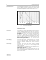
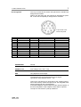
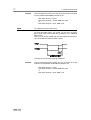
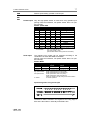
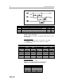
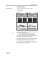
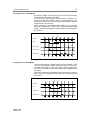
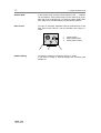
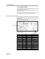
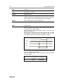
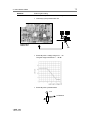
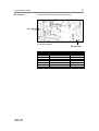
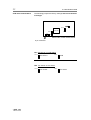
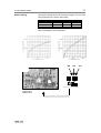
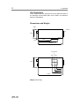
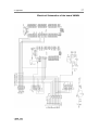
VC45 VM45 Operating Instructions 3 Safety Instructions Safety Instructions For your own safety and in order to guarantee a safe operation of the camera, please read carefully the following information prior to using the device. • Never operate the camera at places where water or dust might penetrate. • Place the camera on a sufficiently stable basis. Shocks like e.g. dropping the camera onto the floor, might cause serious damage to the device. Therefore exclusively the tripod attachment at the bottom side should be used for mounting the camera. • Always unplug the camera before cleaning it. Do not use cleaning liquids or sprays. Instead, use a dry, soft duster. • Make sure that the connecting cable is in good condition and that the link to the socket does not represent an obstacle. • Detach the camera and contact the customer service in the following cases: − When cable or plug are damaged or worn-out. − When water or other liquids have soaked into the device. − When the device is not properly working although you followed all instructions of the user's manual. − When the camera fell to the floor or the housing has been damaged. − When the device shows apparent deviations of normal operation. PCO 1999 VMC45-03/99 5 Contents Contents 1. Video Camera VC45 1.1 Features of the Camera ............................................6 Video Standard ........................................................................... 6 Shutter Control ............................................................................ 6 Long Exposure ............................................................................ 6 1.2 CCD Sensor..............................................................7 Overview of the used sensors ..................................................... 7 Lens-on-chip ............................................................................... 7 Spectral Response...................................................................... 8 1.3 Connections ..............................................................8 Lens Mount ................................................................................. 8 Power Supply .............................................................................. 8 Video Output ............................................................................... 8 Pin Assignment ........................................................................... 9 1.4 Mode Settings .........................................................14 Operating Mode ........................................................................ 14 Long Exposure in Frame Mode ................................................. 15 Long Exposure in Field Mode .................................................... 15 Shutter Mode ............................................................................ 16 Gain Control.............................................................................. 16 Gamma Setting ......................................................................... 16 2. Video Module VM45 Pinning of the I/O Connector ST1.............................................. 17 DIP switches ............................................................................. 21 CCD select and standard .......................................................... 22 Gamma Setting ......................................................................... 23 3. Servicing, Maintenance and Cleaning Instructions Servicing, Maintenance and Cleaning Instructions .................... 24 Cleaning Method for the Optical Part......................................... 24 4. Appendix Customer Service...................................................................... 25 Warranty ................................................................................... 25 CE-Certification ......................................................................... 26 Dimensions and Weight ............................................................ 26 Electrical Schematics of the board VMAIN ................................ 27 System Data ............................................................................. 28 Operating Instructions VC45/VM45 Version 03/99 Subject to change without prior notice!! Copyright by PCO, 1999 PCO 1999 VMC45-03/99 6 1. Video Camera VC45 VC45 VM45 This manual contains important information and instructions for the use of the Video Camera VC45 and the Video Module VM45. If you work with a Video Camera VC45, you will find all necessary information in Chapter 1. Chapter 2 includes additional information when working with a Video Module VM45 (= VC45 without housing). 1. Video Camera VC45 1.1 Features of the Camera The video camera VC45 is a high performance monochrome camera, based on a solid state image sensor. The high quality "lens-on-chip" CCD, combined with an advanced electronics, increases sensitivity of the VC45 substantially, compared with high standard video cameras. An absolute black level is achieved via special darkened reference pixels, yielding a perfect linear relation between light input and output signal. A great number of additional features makes the VC45 suitable for nearly every application. Video Standard Shutter Control Long Exposure The VC45 is easy to use. The analog video signal is a CCIR, respect. a RS170 standard signal and compatible to the whole video equipment on the market. With a potentiometer at the rear panel of the camera the gain can be set externally. An integrated shutter control allows exposure times from 100µs to 20ms (CCIR) respect. 16.7ms (RS170). It can be set by DIP switches, parallel or serial input. A long exposure time can be generated up to 20s by an external or serial input. When using the external input a special power down mode prevents the CCD from additional dark current. There are two integration modes possible: FRAME interlaced and FIELD interlaced. The sensor of the VC45 is absolutely insensitive against overexposure, i. e. too much light cannot damage the CCD sensor. PCO 1999 VMC45-03/99 7 1. Video Camera VC45 1.2 CCD Sensor Overview Lens-on-chip The following CCD sensors can be used in the camera: CCIR format 1/2“ 2/3“ resolution 741 x 576 pixel 741 x 576 pixel pixel size active sensor 8.6 x 8.3 µm 6.4 x 4.8 mm 11.6 x 11.2 µm 8.6 x 6.5 mm RS170 format 1/2“ 2/3“ resolution 756 x 486 pixel 756 x 486 pixel pixel size active sensor 8.4 x 9.8 µm 6.4 x 4.8 mm 11.6 x 13.5 µm 8.8 x 6.6 mm Each of the used CCD sensors have the “lens-on-chip“ integrated which increases the sensitivity of about factor 2. The following drawings show the principle function of the lenson-chip technical. PCO 1999 VMC45-03/99 8 Spectral Response 1. Video Camera VC45 The following drawing shows the spectral response of the used sensors. Optional the VC45 is available with an infrared cutting filter. All wavelength higher than about 680nm will be cut off. = without filter = with infrared cutting filter 1.3 Connections Lens Mount The VC45 uses a C-Mount with a standard back focal length of 17.52mm (distance between the front edge of the C-Mount insert and the focal plane of the CCD sensor). The C-Mount has a fine adjustment to allow for small variations in the focal length of instruments. To adjust to a different back focal length, just loosen the set screw at the bottom of C-Mount front plate. Rotate the C-Mount insert to the desired position. (The C-Mount insert has a 0.5 thread suitable for fine adjustment.) Then secure the insert again by tightening the set screw. Power Supply The power supply (230V), delivered with the VC44, provides 12V (-5%, +10%). At 12V the power consumption is about 300mA. On the power supply a 12-pin special connector is mounted. Video Output The analog video output (BNC socket) supplies a standard video signal (1Vpp, 0.3V Sync-Level on 75Ω) according to CCIR or RS170 standard. The video signal is compatible to all video equipment like recorder, printer, monitors, ... Please use only 75Ω cables (e.g. RG59)! Some monitors need an external Sync-signal. In this case you need a connection between VIDEO OUT of the monitor and SYNC IN of the monitor. PCO 1999 VMC45-03/99 9 1. Video Camera VC45 Pin Assignment The 12 pin socket at the camera rear panel has a standard pin assignment as follows. Please note that there are also special pin assignments possible. In this case a separate pin assignment is enclosed. 12 pin socket of the camera rear panel pin 1 2 3 4 5 6 7 8 9 10 11 12 signal name POWER GND POWER +12V EXP EXPD ENB ED0 ED1 ED2 CSYNC VSYNC MODE GENLOCK level +12V DC TTL TTL TTL TTL TTL TTL TTL TTL TTL Video, TTL* function ground input power exposure exposure power down enable shutter shutter control shutter control shutter control composite sync vertical sync frame / field integration genlock input / output input input input input input input input input output output input input * signal level from 1 ... 5V is accepted POWER GND Ground POWER +12V Input voltage 12V (+10% / -2%) EXP Long Exposure Control input TTL level The exposure time can be prolonged by a low signal. Typical time range between 40ms ... 10s. This input is checked at any rising edge of the VSYNC signal (= end of the VSYNC). When the input is low, the integration time will be prolonged for the next field/frame. In the field integration mode multiple of 20ms will be exposed, in the frame integration mode multiple of 40ms will be exposed. The input is connected to a pull-up resistance. PCO 1999 VMC45-03/99 10 1. Video Camera VC45 Remark The Long Exposure Control can only be active when the module is in the parallel mode and the shutter is off! DIP switch S1/pin 7 = open DIP switch S1/pin2 = closed; ENB don’t care or DIP switch S1/pin2 = open; ENB = low EXPD Long Exposure Power Down input TTL level For long integration times, the sensor can be set in a powerdown mode. This mode avoids the generating of an additional dark current. This input can be set parallel with the EXP input but must be reset at least 200ms before the EXP is reset. The input is connected to a pull-up resistance. Remark The Long Exposure Power Down can only be active when the module is in the parallel mode and the shutter is off! DIP switch S1/pin 7 = open DIP switch S1/pin2 = closed; ENB don’t care or DIP switch S1/pin2 = open; ENB = low PCO 1999 VMC45-03/99 11 1. Video Camera VC45 ENB ED0 ED1 ED2 Shutter speed setting, parallel or serial input. Parallel Input Only the high-speed shutter is used when using parallel input. (During frame accumulation, low-speed shutter does not operate normally). Shutter speed table JP1 ENB ED0 ED1 ED2 shutter speed X L X X X shutter off 1) L H H H H 1/60 1) H H H H H 1/50 L H L H H 1/100 H H L H H 1/120 X H H L H 1/250 X H L L H 1/500 X H H H L 1/1000 X H L H L 1/2000 X H H L L 1/4000 X H L L L 1/10000 1) Accumulation time is as follows regardless of field accumulation / frame accumulation: JP1 = low (EIA RS170), 1/60s JP2= high (CCIR), 1/50s (Pseudo field readout during frame accumulation) Serial Input The following four modes can be selected according to the combination of serial data SMD1 and SMD2. (During frame accumulation, low-speed shutter does not operate normally). Shutter Mode mode flickerless high-speed low-speed no shutter shutter shutter SMD1 L L H H SMD2 L H L H flickerless: eliminates flicker resulting from the frequency of fluorescent light high-speed shutter: shutter speed higher than 1/50 (CCIR) shutter speed higher than 1/60 (RS170) low-speed shutter: shutter speed lower than 1/50 (CCIR) shutter speed lower than 1/60 (RS170) (does not operate normally during frame accumulation no shutter no shutter operation Input timing when using serial input The data on ED2 is latched in the register at the rising edge of ED1 and is then taken in internally while ED0 is low. PCO 1999 VMC45-03/99 12 1. Video Camera VC45 symbol ts2 th2 ts1 tw0 ts0 ED2 setup time against the rising edge of ED1 ED2 hold time against the rising edge of ED1 ED1 rising setup time against the rising edge of ED0 ED0 pulse width ED0 rising setup time against the rising edge of ED1 min: 20ns 20ns 20ns 20ns 20ns max: 50µs Shutter speed calculation (During frame accumulation, low-speed shutter does not operate normally). High-speed shutter ... for CCIR: T=[31210-(1FF16-L16)] x 63.56 + 34.78µs ... for RS170: T=[26210-(1FF16-L16)] x 64 + 35.6µs (L16 = load value) load value 0C816 0CA16 0CE16 0D616 0E616 1o516 14316 14916 CCIR shutter speed 1/10000 1/4000 1/2000 1/1000 1/500 1/250 1/125 1/100 calculated value 1/10040 1/4394 1/2068 1/1004 1/495 1/250 1/125 1/120 load value 0FA16 0FC16 10016 10816 11816 13716 17616 19616 RS170 shutter speed 1/10000 1/4000 1/2000 1/1000 1/500 1/250 1/125 1/100 Low-speed shutter N = 2 x (1FF16-L16) FLD However, 1FF cannot be used as the load value. Maximum 1023 fields à 20ms (= 20 seconds). load value 1FE16 1FD16 ... 10116 10016 PCO 1999 VMC45-03/99 shutter speed (FLD) 2 4 ... 508 510 calculated value 1/10169 1/4435 1/2085 1/1012 1/499 1/252 1/125 1/100 13 1. Video Camera VC45 CSYNC Composite synchronisation output TTL level VSYNC Vertical synchronisation output TTL level MODE Switch between field-frame readout and integration TTL level mode low high GENLOCK readout field frame External synchronisation Input to synchronise the camera to an external video device. A video signal (75Ω) or a TTL signal, consisting of horizontal and vertical synchronize pulses (composite sync, CSYNC) is needed. (Internally there is no 75Ω termination.) The synchronisation is achieved by an internal PLL. The synchronisation with Genlock can be enabled/disabled by controlling LSW. This can be done with DIP switch S1: DIP switch S1/pin 8 = open DIP switch S1/pin 8 = closed PCO 1999 VMC45-03/99 Genlock disabled Genlock enabled 14 1. Video Camera VC45 1.4 Mode Settings Operating Mode The camera runs in two different operating modes: • FRAME interlaced • FIELD interlaced FRAME FIELD INTERLAFIELD 1 INTERLA- FIELD 2 1 FIELD 1 2 3 4 5 6 Integration Time: 2 x 40ms (CCIR) 2 x 33.4ms 1 2 3 4 5 6 Integration Time: 2 x 20ms (CCIR) 2 x 16.7ms Image 1 Image 1 Image 2 Image 2 Video Out Video Out 1 Hint FIELD 2 1 2 3 4 5 6 2 1 2 At continuous illumination the brightness of the image is the same in FIELD or FRAME mode: CCIR: 40ms with 1 pixel or 20ms with 2 pixels RS170: 33ms with 1 pixel or 16.5ms with 2 pixels However, with externally applied shuttering (e.g. flashlight or laser pulse), the FIELD mode generated image has double the brightness of a FRAME mode generated image. In the FRAME interlace mode the camera produces two fields generated with a time shift FIELD 1 and FIELD 2 (odd respect. even lines). These fields are each integrated for 40ms. The FIELD interlace mode combines 2 lines (1+2, 3+4, ... in FIELD 1 and 2+3, 4+5, ... in FIELD 2). FIELD 2 is shifted by one line in respect to FIELD 1 (line shifting). PCO 1999 VMC45-03/99 15 1. Video Camera VC45 Long Exposure in Frame Mode By using the EXP (= exposure) input (pin 3 of the 12-pin socket) the integration time can be controlled. In line 10 of the video signal a marker pulse is allocated. If in this moment the EXP signal is "high", the marker pulse is suppressed, the image is not shifted into the shift-register and the integration time is prolonged. When operating in the FRAME mode, always 2 x n marker pulses are suppressed, to achieve two evenly illuminated fields (40ms). During the integration, black pictures are released from the camera. *) *) 20ms VSYNC EXP odd 1 Integr. ODD even 1 Integr. EVEN VIDEO OUT odd 2 odd 3 even 2 even 3 black image even odd even odd even odd 1 even 1 odd 2 even 2 *) Marker pulse (in video line 10) is suppressed, thus yielding longer integration time. Long Exposure in Field Mode Via the EXP signal the integration time can be controlled. In line 10 of the video signal a marker pulse is allocated. If in this moment the EXP signal is "high", the marker pulse is suppressed, the picture not shifted in the shift register and integration time prolonged. The FIELD mode allows integration time prolongation in steps of 20ms. During the integration, black pictures are released from the camera. *) *) 20ms VSYNC EXP Integration VIDEO OUT field x field x+1 field x+2 black image field x field x+1 field x+2 *) Marker pulse (in video line 10) is suppressed, thus yielding longer integration time. PCO 1999 VMC45-03/99 16 1. Video Camera VC45 Shutter Mode In the shutter mode, exposure times between 1/50 ... 1/10000 s can be realized. These shutter times can be achieved by a parallel and serial programming via external signals (ENB, ED0, ED1, ED2) or by a parallel setting via internal DIP switches. Gain Control The gain is externally adjustable with the potentiometer at the back panel of the camera. It can be selected in the range of ± 12dB. 1 2 3 1 Gamma Setting PCO 1999 VMC45-03/99 2 12-pin Socket Gain Potentiometer Analog Video Output 3 The gamma correction is preset by factory to "linear". If you want to change it, internal changes are necessary (see Chapter 2). 17 2. Video Module VM45 2. Video Module VM45 The main features of the Video Module VM45 are identical to these of the Video Camera VC45. In this Chapter you will find some additional information to the Video Module VM45. Please note that there are parallels between the 12-pin socket at the camera rear panel and the internal connector ST1. Pinning of the I/O Connector ST1 The connector ST1 is placed on the lower (larger) board. Some signals has parallel wires to the I/O connector ST1 and to the DIP switch S1. When using the external interface (I/O connector ST1) all DIP switches must be set to off! ST1 lower board VMAIN DIP switch S1 pin at internal signal pin at 12-pin function connector ST1 name connector 1 GND X 1 ground 2 +12V X 2 input power 3 GND X 1 ground 4 +5Vout -input or output power 5 GND X 1 ground 6 VIDEO -video out 7 TRIG -trigger input 8 GAIN ext -external gain 9 ENB X 5 enable shutter 10 ED0 X 6 shutter control 11 ED1 X 7 shutter control 12 ED2 X 8 shutter control 13 EXPD X 4 exposure power down 14 EXP X 3 exposure 15 CSYNC X 9 composite sync 16 MODE X 11 frame / field integration 17 VSYNC X 10 vertical sync 18 HSYNC -horizontal sync 19 VR -vertical reset 20 GENLOCK X 12 genlock The ‘X’ marked signals are already described in Chapter 1 (see page 9). PCO 1999 VMC45-03/99 18 2. Video Module VM45 GND Ground +12V see Chapter 1, page 9 +5Vout Output of a +5V Regulated by an internal voltage regulator (7805). When the voltage regulator is not needed you can also use an external 5V power supply. In this case the regulator has to be bridged. VIDEO Video output signal, CCIR or EIA RS170 1Vpp, 0.3V Sync-Level on 75Ω TRIG Trigger mode Continuously variable shutter When using the normal shutter, either leave the TRIG pin open or connect it to the power supply. When using the continuous variable shutter, input the clock pulse to the TRIG pin When using the TRIG pin to control the exposure time, in order to broaden the control range it is necessary to use the ED=, ED1, and ED2 pins to set the shutter speed to 1/10000. VSYNC HSYNC TRIG XSG exposure time From the start of the TRIG input (falling edge) to the XSG pulse there is a variable exposure time. The XSG pulse is done in the following lines after the vertical sync has ended: CCIR EIA RS170 PCO 1999 VMC45-03/99 8 lines 8.5 lines 1.5 lines 1 line odd field even field odd field even field 19 2. Video Module VM45 GAIN ext External gain setting There are three possibilities to control the gain: • Internally by the potentiometer P2 GND upper board VIDEO SPC P2 • Externally with a voltage range of 0 ... 5V The gain range is between 5 ... 32 dB. • Externally with a potentiometer: +5 V to GAINext 10kΩ PCO 1999 VMC45-03/99 20 2. Video Module VM45 ENB see Chapter 1, page 11 ED0 see Chapter 1, page 11 ED1 see Chapter 1, page 11 ED2 see Chapter 1, page 11 EXPD see Chapter 1, page 10 EXP see Chapter 1, page 9 CSYNC Composite synchronisation output (CSYNC) TTL level MODE see Chapter 1, page 13 VSYNC see Chapter 1, page 13 HSYNC Horizontal synchronisation output (HSYNC) TTL level VR Vertical reset input (TTL level) A vertical image synchronisation can be made with a vertical sync signal GENLOCK External synchronisation Input to synchronise the camera to an external video device. A video signal (75Ω) or a TTL signal, consisting of horizontal and vertical synchronize pulses (composite sync, CSYNC) is needed. The synchronisation is achieved by an internal PPL. A second possibility is to input separately the horizontal sync and the vertical sync. In this case the horizontal sync must be connected to the GENLOCK and the vertical sync must be connected to the vertical reset (VR). The synchronisation with Genlock can be enabled/disabled by controlling LSW. This can be done with DIP switch S1: DIP switch S1/pin 8 = open DIP switch S1/pin 8 = closed PCO 1999 VMC45-03/99 Genlock disabled Genlock enabled 21 2. Video Module VM45 DIP switches The 8 DIP switches have the following function: ST1 lower board VMAIN DIP switch S1 DIP switch S1 1 2 3 4 5 6 7 8 PCO 1999 VMC45-03/99 function TRIG ENB ED0 ED1 ED2 Mode PS (parallel / serial) Genlock factory set open closed open open open open open open 22 CCD select and standard 2. Video Module VM45 The following jumpers are factory settings and are not allowed to change! Pin 1 CXD 1261 Pin 1 JP2 JP1 bottom side of lower board VMAIN 6 pin connector JP1: EIA RS170 or CCIR setting Pin 1 EIA RS170 Pin 1 CCIR JP2: 1/2“ sensor or 2/3“ sensor Pin 1 PCO 1999 VMC45-03/99 1/2“ sensor Pin 1 2/3“ sensor 23 2. Video Module VM45 Gamma Setting The gamma setting can be done with the jumpers JP3, JP4 and JP5, jumpered on the board "Video SPC". Linear Gamma 1 Gamma 2 JP3 off off on JP4 on off off JP5 off on on Other combinations are not allowed !! JP5 GND upper board VIDEO SPC PCO 1999 VMC45-03/99 JP4 JP3 24 3. Servicing, Maintenance and Cleaning Instructions 3. Servicing, Maintenance and Cleaning Instructions Servicing, Maintenance and Cleaning Instructions The camera is maintenance-free. Factory settings make any inspection and servicing superfluous. During use the camera should be protected from hard shocks or strong vibrations. Also should the camera be protected from high humidity and temperature shocks. Avoid exposing to sunlight, since it heats up the camera housing unnecessarily and prevents the cooling from reaching its optimum operating temperature. Keep apertures and slots free to allow air to circulate. Objective lens or lens adapter should be screwed in gently. Avoid forcing as it will damage the tread. Use a soft and dry cloth to clean the housing. Cleaning Method for the Optical Part In principle every cleaning method bears the danger of damaging an optical surface. Therefore clean only if it is strictly necessary. As a first step use dry air to blow out dust particles. Avoid strictly to wipe on a dry glass surface. In case dirt cannot be removed by blowing, use special optical cleaning fluids. Adequate fluids for optical surfaces are: pure dehydrogenated alcohol, pure acetone or cleaning fluids available in photo shops. Use a soaked cotton tip and take care to wipe only on glass surfaces, avoiding contact to metal surfaces, e.g. C-Mount thread, otherwise microscopic dirt and metallic chips are released, causing irreparable scratches on the glass surface. Never use aggressive cleaning substances, e.g. benzine, spirit, nitro solvents, etc. commonly found in labs. Such substances may destroy or damage the surface on which they are applied. The best is to avoid any dirt on optical parts, e.g. by replacing immediately the black protection cap when removing the objective lens. Do not leave the camera’s optical input window open, without lens or protecting cap. Our warranty does not cover damaged optical surfaces caused by improper cleaning methods. PCO 1999 VMC45-03/99 25 4. Appendix 4. Appendix Customer Service Having a problem or a question about matters not handled in these operating Instructions, we recommend to contact us : ... by phone +9441 / 2005-0 ... by fax +9441 / 2005-20 ...by email [email protected] For a quicker reply we need following information: • Short description of the problem • experiment conditions • Camera serial-number (on the label placed on the bottom of the camera) Typ: VC45 S/N: .... Warranty PCO grants a 12 month warranty period for the camera. The warranty period starts on day of delivery ex-factory. In case of defect within the warranty period replacement or repair will be made (at PCO’s discretion) free of charge. The device shall be returned on customer’s expenses to PCO, preferably in the original package. PCO is not liable for consequential damages. Before returning the camera, contact PCO via any of the Customer Services. Pay attention to use a sufficient package if you have to send the camera via mail (keep the original package). Attention PCO 1999 VMC45-03/99 Opening of the camera or improper handling (e.g. damage by electrostatic charge, wrong cleaning method) voids the warranty. 26 4. Appendix CE-Certification VC45 complies with the requirements of the „EMC Directions of the European Communities (089 / 336 / EWG)“ and therefore bears the CE-Marking. Dimensions and Weight BNC C-Mount 39mm 8,3mm 12mm 75mm 110mm 130mm 1/4”-20 UNC M6 M6 47mm 25mm 37mm 50mm 130mm Weight: about 300g PCO 1999 VMC45-03/99 27 4. Appendix Electrical Schematics of the board VMAIN PCO 1999 VMC45-03/99 28 4. Appendix System Data Model VC45-C-12 VC45-C-23 Sensor format 1/2“ sensor 2/3“ sensor Video Standard CCIR Pixel Resolution 741 x 576 741 x 576 Pixel Size 8.6 x 8.3µm 11.6 x 11.2µm Active Sensing Area 6.4 x 4.8mm 8.6 x 6.5mm Horizontal Scanning Fre- 15.625 kHz 15.625 kHz quency Vertical Scanning Fre- 50Hz 50Hz quency Aspect Ratio 4/3 (hor./ver.) max. S/N ratio > 55dB Gamma linear, gamma 1, gamma 2 Shutter Control 100µs ... 20ms Long Exposure Internal: up to 20s External: up to DC Gain Control internally or externally Operating Mode FRAME or FIELD interlaced Power Supply 12V DC Weight 290g Dimensions 47(W) x 39(H) x 130(L) mm PCO 1999 VMC45-03/99 VC45-N-12 VC45-N-23 1/2“ sensor 2/3“ sensor EIA RS170 756 x 486 756 x 486 8.4 x 9.8µm 11.6 x 13.5µm 6.4 x 4.8mm 8.8 x 6.6mm 15.734 kHz 15.734 kHz 60Hz 60Hz 4/3 (hor./ver.) > 55dB linear, gamma 1, gamma 2 100µs ... 16.7ms Internal: up to 20s External: up to DC internally or externally FRAME or FIELD interlaced 12V DC 290g 47(W) x 39(H) x 130(L) mm Dear Customer, We hope the VC45 / VM45 will be an always valuable tool for your scientific day in, day out work. Comments, suggestions or any new idea on our system are welcome. We are at your disposal at any time, also after your buying of this camera. Your PCO Team