1
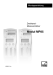
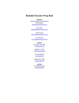
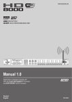
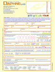
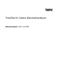
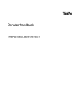
Jaw Motion
Analysis System
Specifications
and
Operating Instructions
zebris Medical GmbH
www.zebris.de
Text-Release: 24/07/2013
Inhalt
1
USER NOTES ........................................................................................................................... 3
1.1
INTRODUCTION ........................................................................................................................ 3
1.2
MANUFACTURER AND SALES ...................................................................................................... 4
1.3
LAYOUT OF THE USER MANUAL FOR THE FDM SYSTEM ................................................................. 4
1.4
CONVENTIONS AND SYMBOLS USED ........................................................................................... 5
2
AREA OF USE AND SAFETY ................................................................................................... 6
2.1
INTENDED USE......................................................................................................................... 6
2.1.1 USE ........................................................................................................................................ 6
2.1.2 ARTICULATORS ........................................................................................................................ 7
2.1.3 DATA EXPORT ......................................................................................................................... 7
2.2
SAFETY................................................................................................................................... 8
2.2.1 ENVIRONMENTAL CONDITIONS ................................................................................................... 8
2.2.2 STORAGE AND TRANSPORT ....................................................................................................... 8
2.2.3 OBLIGATIONS OF THE USER ....................................................................................................... 9
2.2.4 GENERAL SAFETY INFORMATION .............................................................................................. 10
2.2.5 SAFETY INFORMATION ON HEART PACEMAKERS/DEFIBRILLATORS................................................. 11
2.2.6 PROHIBITED USE ................................................................................................................... 11
3
PRODUCT DESCRIPTION ...................................................................................................... 12
3.1
SYSTEM COMPONENTS ........................................................................................................... 12
3.2
TECHNICAL DATA OF THE JMANALYSER MEASUREMENT SYSTEM ................................................. 12
3.3
MEASURING PRINCIPLE ........................................................................................................... 13
3.4
CONTROL ELEMENTS AND CONNECTORS .................................................................................. 14
3.5
MEANING OF THE DISPLAY LIGHTS............................................................................................ 15
3.6
ASSIGNMENT OF THE CONNECTING SOCKETS............................................................................. 16
3.1
DIGITAL INPUTS...................................................................................................................... 17
3.2
EMG FOR THE DETERMINATION OF THE MUSCLE TONE OF THE JAW MUSCLES ................................ 17
3.3
ACCESSORIES AND SPARE PARTS ............................................................................................ 18
4
PUTTING THE MEASUREMENT SYSTEM INTO OPERATION............................................... 21
4.1
POWER SUPPLY AND CHARGING THE BATTERY (ONLY JMANALYSER BT) ...................................... 21
4.2
COMPUTER REQUIREMENTS .................................................................................................... 22
4.3
INSTALLING THE ZEBRIS DENTAL SOFTWARE ........................................................................... 23
4.4
CONNECTING THE ACCESSORY PARTS ...................................................................................... 23
4.5
CONNECTION OF THE BASIC UNIT VIA USB INTERFACE................................................................ 24
4.6
CONNECTION OF THE BASIC UNIT VIA BLUETOOTH INTERFACE ..................................................... 25
4.7
TAKING THE MEASUREMENT SYSTEM OUT OF OPERATION ............................................................ 25
5
CONTROL MEASURES, PREPARATION, DISPOSAL .......................................................... 26
5.1
MANDATORY PERIODIC INSPECTIONS AND STK ......................................................................... 26
5.2
CHECKING THE MEASUREMENT FUNCTION ................................................................................. 27
5.3
TROUBLESHOOTING................................................................................................................ 28
5.4
PREPARATION METHODS ........................................................................................................ 29
5.4.1 MANUAL CLEANING ................................................................................................................. 29
5.4.2 MANUAL DISINFECTION ........................................................................................................... 30
5.4.3 STERILIZATION ....................................................................................................................... 30
5.6
DISPOSAL ............................................................................................................................. 31
5.6.1 PACKAGING ........................................................................................................................... 31
5.6.2 DISPOSAL OF ELECTRONICS .................................................................................................... 31
6
SAFETY STANDARDS AND SYSTEM CLASSIFICATION ...................................................... 32
6.1
CLASSIFICATION ACC. TO ANNEX IX OF DIRECTIVE 93/42/EEC ................................................... 32
6.2
SAFETY OF MEDICAL ELECTRICAL DEVICES ................................................................................ 32
6.2.1 CONNECTING THE JMANALYSER - SYSTEM TO OTHER ELECTRICAL DEVICES.................................. 32
6.2.2 VICINITY OF THE PATIENT / TEST PERSON .................................................................................. 33
6.3
ELECTROMAGNETIC COMPATIBILITY GUIDELINE & MANUFACTURER DECLARATION ......................... 34
6.4
KONFORMITÄTSERKLÄRUNG .................................................................................................... 37
7
NOTE ...................................................................................................................................... 38
zebris Medical GmbH
JMAnalyser Technische Daten und Gebrauchsanweisung
Seite 2/38
1 User Notes
1.1 Introduction
Welcome to the User Manual for Jaw Motion Analysis.
This User Manual provides a basic understanding for operating the JMAnalyser+ measuring system for the contact-free analysis of all the 3D movements of the lower jaw, using
the method for measuring the travel-time of ultrasound pulses. It explains the basic set-up
and operation of the system, and provides tips on preparation for measuring and data
acquisition. Technical information on the system and safety precautions can be found in
this technical User Manual.
All particulars about the measurement system, in this book, were prepared, compiled, and
edited with the greatest of care. Nevertheless, we cannot guarantee that mistakes do not
appear. We advise the user that zebris Medical GmbH neither provides a guarantee
against, nor accepts any legal responsibility or any liability for consequences resulting from
incorrect statements.
The company zebris Medical GmbH does not assume any liability whatsoever for injury to
personnel or patients, or damage to the device caused by improper use of the
JMAnalyser+ System.
If you notice any mistakes in this manual, or should you have any suggestions for the
improvement, we would be very grateful for giving us a short message any time.
In the interests of continuous product development, the manufacturer reserves the right to
carry out improvements to this manual and the product described therein at any time and
without any further obligation.
Registered trade marks
Several brand names are referred within this User Manual. All these product names are
used only for clarity’s sake or for editorial reasons and are trademarks belonging to the
respective companies. When using the brand names, the trade marks them and also the
rights of the respective proprietors remain protected.
The name zebris is a registered trade mark and JMAnalyser+ identifies a product of the
company, zebris Medical GmbH.
Copyright
This document and extracts taken from it may on no account be duplicated without the
explicit consent of zebris Medical GmbH. The content of this document may on no account
be used for purposes that have not undergone approval by zebris Medical GmbH. Any infringement of the copyright is a punishable offence.
© Copyright zebris Medical GmbH
All rights reserved.
zebris Medical GmbH
JMAnalyser Technische Daten und Gebrauchsanweisung
Seite 3/38
1.2 Manufacturer and sales
zebris Medical GmbH
Max-Eyth-Weg 43
Phone
+49 (0)7562 9726 0
88316 Isny im Allgäu
Telefax +49 (0)7562 9726 50
Deutschland
E-Mail
[email protected]
Web: www.zebris.de
1.3 Layout of the user manual for the FDM System
The user manual of the JMAnalyser+ Jaw Motion System consists of several parts:
1. JMAnalyser system technical specifications and user manual
2. zebris DENTAL user manual of the application software
The section JMAnalyser Specifications and Operating Instructions and user manual primarily contains information on technical data and the operation of the JMAnalyser system
sensor technology as well as on their safe operation. Notes regarding the accessories are
limited to essential safety and maintenance measures and hygiene procedures.
WARNING
zebris Medical GmbH
The exact adherence to the instructions in all sections of the operating Instructions for the measuring system is a precondition for its
intended use.
JMAnalyser Technische Daten und Gebrauchsanweisung
Seite 4/38
1.4 Conventions and Symbols Used
The green markings in the margin of the User Manual denote
new information about the product safety.
“WARNING” symbols indicate a potential hazard to the health
and safety of the users and/or patients. The warnings describe
the risks involved and those can be avoided.
“NOTE” symbols indicate a potential risk which could lead to
damaging of the device. These NOTE symbols describe the risks
involved and how those can be avoided.
The CE mark on the type plate confirms the conformity of the
measuring system with the Directive 73/23/EEC and Directive
89/366/EEC (Low Voltage Directive and EMC Directive).
The CE mark with reference number 0535 of notified body BSI
(formerly EUROCAT) on the type plate confirms the conformity
of the system with the Directive 93/42/EEC for Medical Devices.
Symbol for manufacturer and date of production.
Device of type BF according to DIN EN 60601-1
Symbol for the connection of the external power supply unit
(DC voltage 15-20V with indicated polarity)
USB-Interface
The symbol indicates that in accordance with the Directive
2002/96/EEC (Waste Electronic and Electrical Equipment Directive) and national laws, a product must not be disposed of in
the household waste, and that within Europe it has to be disposed of in a special way.
Carefully read the accompanying documentation, particularly all
information concerning product safety
zebris Medical GmbH
JMAnalyser Technische Daten und Gebrauchsanweisung
Seite 5/38
2 Area of use and safety
2.1 Intended Use
The zebris JMAnalyser system calculates from the recorded jaw movements of the patient
all the necessary parameters with the objective of designing a functional prosthesis and
splints. The measuring system also allows the output of functional parameters for the programming of virtual and mechanical articulators and export of data for further processing
with CAD/CAM or DVT systems.
Furthermore, the system allows the therapeutic positioning of the mandible in a jaw relation.
The measuring system must only be used by trained dentists.
The application environment is limited to dental facilities.
A measurement is performed within 15 minutes, and should not be used on open wounds
in the oral and head area, where it may be used in patients of any age who are able to
mentally follow the operator instructions exactly.
2.1.1 Use
zebris JMAnalyser systems are electronic registration systems that are based on 3D ultrasound measurements. zebris JMAnalyser systems capture the individual mandibular
movements of patients in all degrees of freedom which are necessary for the production of
functional dentures and splints.
The 3D representation of the positions and movement traces occlusal or joint near measurement points are particularly important information on the movement behavior of the
temporomandibular joint and the lower or upper jaw teeth. The 3D representation of prominent positions in the face is a classification of the symmetry of the face to prepare the
denture.
In a preliminary functional assessment discoordinations and movement limitations can be
analyzed and documented. The system is able to determine a neuromuscular jaw relation
in the situation.
The electronic position analysis of the condyles allows the comparison of different occlusal
positions and can thus give indications of possible pain vectors in the joint.
By means of a separate software module, an analysis of chewing movements can be realized.
The system determines the adjustment of fully adjustable virtual or mechanical articulators.
In conjunction with the zebris DAB Bluetooth the JMAnalyser product family enables the
analysis of TMJ sounds by means of highly sensitive in the joint area placed borne noise
microphones and functional tests of various muscle groups such as temporalis anterior
and masseter.
The XML export function allows the use of the determined jaw movements in CAD/CAM
systems and CBCT systems for functional optimization of dental restorations and occlusal
splints.
zebris Medical GmbH
JMAnalyser Technische Daten und Gebrauchsanweisung
Seite 6/38
The zebris JMAnalyser system is used to support the functional diagnosis. The measuring
sensor consists of a receiver and a transmitter. It is attached to the patient's head. The
lower jaw sensor is equipped with a special locking mechanism for the attachment. The
face bow is put forward by means of support on the nasion and applied to the back of the
head above the ears. A measurement can then be carried out, according to the desired
settings and measured parameters on the software.
All measuring and analytical results of the zebris JMAnalyser system should always be
interpreted in the light of the clinical history of the patient and in the context of other diagnostically methods of a demonstrably trained person and examined for relevance. If invasive measures are taken, the measurement system should only be used as an additional
assessment method. Under no circumstances can or should invasive surgery or measures
that put the patient at risk be carried out based on the measurement result alone
2.1.2 Articulators
With the help of the zebris JMAnalyser+ system is it possible to adjust the following articulators:
·
Artex AR (Girrbach/Amann)
·
KaVo PROTAR 7
·
SAM
·
Stratos 300 (lvoclar)
2.1.3 Data Export
The XML export function allows the use of determined jaw movements in CAD/CAM systems and CBCT systems for functional optimization of dental restorations and occlusal
splints. As a reference for data matching serves a bite fork. This bears reference marks
which of imaging systems such as Surface scanner or DVT can be detected.
zebris Medical GmbH
JMAnalyser Technische Daten und Gebrauchsanweisung
Seite 7/38
2.2 Safety
2.2.1 Environmental conditions
The JMAnalyser +jaw motion analysis system is suitable for use in dry interior rooms, as
can be found in clinics, medical practices and laboratories.
Temperature range
10°C to 40°C
Relative humidity
30% to 70%
The Jaw motion systems must NOT be operated in wet zones, wet
rooms (swimming pools, saunas) or climatic chambers.
The measuring systems are not intended for operation in potentially
explosive atmospheres of medically used rooms or oxygen-enriched
atmospheres.
WARNING
The devices must not be operated in proximity to e.g. engines or
transformers with a high connected load as well as mains current
lines, as electrical or magnetic interference fields can falsify correct
measurements resp. turn them impossible.
To avoid reciprocal faults from occurring, two SICAT JMT+ systems
should never be operated in the same room or near other ultrasound
emitting devices (e.g. ultrasonic cleaners, bird scare devices, alarm
systems), as this can cause the measured values to be falsified.
2.2.2 Storage and Transport
Storage and transport of the measuring system are only to be effected in the original
packaging provided by zebris.
Storage temperature
-20°C to +70°C
Relative humidity
5% to 90%
Air pressure
700 hPa to 1060 hPa
zebris Medical GmbH
JMAnalyser Technische Daten und Gebrauchsanweisung
Seite 8/38
2.2.3 Obligations of the user
·
The general guidelines and/or national legislation, national regulations and technical
regulations pertaining to medical products are to be applied and fulfilled both with the
start-up and during the operation of the zebris product appropriate tot he stated purpose. In Germany, operators, those responsible for such devices, and users are
obliged to operate their devices in compliance with the MPG (Medical Devices Act)
regulations.
·
It is the obligation of the user:
ü to comply with all the safety instructions stated in the operating instructions.
ü to carry out all of the inspection and maintenance work regularly as specified in the
operating instructions
ü to only use fault free working equipment.
ü to ensure all the provided operating instructions that from part of the measurement
system, are accessible to all users at all time, and to keep them near the measurement system
ü to ensure that the device is functionally safe and in a proper stat prior to every instance of use of the device.
ü to protect oneself, the patients and third parties against dangers.
ü to prevent a contamination occurring due to the product
·
During use, it is necessary to comply with the legal regulations especially:
ü The current work safety regulations.
ü The current accident prevention measures.
·
Responsibility is assumed to ensure the safety, reliability and effective performance of
all measurement systems and accessories delivered by zebris, such that:
ü assembly work, extensions, new setting, changes or repairs are carried out by
zebris authorized, trained technicians or by personnel of authorized dealers. The
storage and transport should only be carried out in the original packaging, as provided by the manufacturer.
ü the product operated in compliance with the operating instructions.
ü the information technology components provided by the operator comply with the
technical requirements for hardware and software contained in these operating instructions, and that they are installed and set up according to the applicable descriptions for these components.
ü the place of installation corresponds with the specified environmental conditions for
the measurement system and the current installation regulations.
ü Only the software made available by zebris, as well as the components and accesory parts listed in these operating instructions are used with the system.
zebris Medical GmbH
JMAnalyser Technische Daten und Gebrauchsanweisung
Seite 9/38
2.2.4 General safety Information
·
The use and operation of the system and the evaluation of measurement data and its
interpretation should only be carried out by trained specialist personnel. The manufacturer assumes no liability for damage to persons or property, or the loss of data that
may occur due to the improper use of the software, the device, or its accessory parts.
·
Patients and measurement data may only be copied, moved or deleted with the help of
the database function that is provided by the zebris softwar application. In the case of
the deliberate changing of data without the database function, the user alone bears the
full risk.
·
Measurement and analysis results should always be interpreted in the light of the clinical history of the patient and in the context of other diagnostic tests by a trained person proven and tested for their relevance.
·
Should any measures for treatment be taken on the basis of the measuring results, the
measuring system may only be implemented as a supplementary means for evaluation
by an expert. On no account can, or may invasive measures, or measures endangering the patient be carried out solely on the basis of the measuring results without further verification of the measuring data by additional methods.
·
In the case of malfunctions and/or defects being suspected and/or ascertained, the
device has to be taken out of use immediately, labeled as ‚Out of Use‘, and secured to
prevent use. The manufacturer or authorized sales partner must always be contacted
in all cases of fault or doubt.
·
The measuring system must be checked at regular intervals to make sure it is functioning properly. More details on this can be found in the section, "Maintenance of the
Device" in this User Manual.
·
Do not install the jaw motion analysis system near a source of heat or in direct sunlight
behind a window, as excessive heating can lead to incorrect measurement results.
·
Be sure that all the mains and connection cables are laid safely and that they are protected against stepping on, so that nobody can trip over them. Check all the cables
and the connection plug regularly for any damage. Damaged power Supply’s and cables have to be replaced before further operation.
·
The measurement system is not protected against the penetration of fluids. If fluid
penetrates the measurement system, switch it off and please contact the zebris Medical GmbH technical service team.
·
Never introduce objects into components of the measurement system.
·
Before starting every measurement, it is necessary to ensure the correct choice and
correct position of the transmitters or application aids. The cables or the application
aids (e.g. Pointer) can present a risk of injury to the patient. In this context, please
consult the special instructions in the handbooks of the application software, and do
not allow children or mentally impaired patients to enter the proximity of the device
without supervision.
zebris Medical GmbH
JMAnalyser Technische Daten und Gebrauchsanweisung
Seite 10/38
2.2.5 Safety information on heart pacemakers/defibrillators
·
In the magnetic coupling for the attachment of the lower jaw sensor on the Tattachment there are strong permanent magnets, such as those that are used on
headphones on MP3 players. Under especially unfavorable circumstances, at short
distances (<15 cm), these magnets can have a negative impact on the functionality of
certain implanted heart pacemakers and defibrillators. Therefore, the lower Jaw - sensor should not be positioned on the upper body of the patient on patients with electronic implants.
·
Version BT devices contain a Bluetooth transmitter as an interface to the PC. Although
there is so far no evidence of a possible interference of heart pacemakers / defibrillators by Bluetooth transmitters, the JMAanalyser+ system is not recommended to be
used on patients with electronic implants using the neck strap, but with the
maintaining of a safety distance of at least 15 cm from the patients thorax.
·
No interference of electronic implants is to be expected from the ultrasonic transmitters
used in the measurement system, as the JMAnalyser+ system works with airborne
sound and very low sound power of a few millimeters. Due to the adverse connection
during the transition from the air into the human body, the noise intensity of the measurement signals is weakened strongly such that any interference with implants, as well
as any damage to issue, is excluded.
2.2.6 Prohibited Use
·
Improper and/or prohibited use of the measurement system is not permitted an express warning is herewith provided of such.
·
Do not under any circumstances attempt to maintain or prepare the measurement system in any way other than as described in the operating instructions. This could cause
the high sensitivity sensor technology to be in impaired terms of its measurement accuracy
·
In the case of malfunctions and/or defects being suspected and/or ascertained, the
device has to be taken out of use immediately, labeled as ‚Out of Use‘, and secured to
prevent use, with the on/off switch being covered and secured with adhesive tape.
·
Changing or modifying the measurement system or its accessory parts without the
written permission of zebris Medical is not allowed. If the device is changed without
permission, the operator is obliged to carry out suitable examinations and inspections
in order to guarantee the secure use.
·
zebris measurement systems must not be operated in environmental conditions other
than those stated in the ‚technical data‘ chapter (e.g. in an oxygen enriched environment, wet zones, damp rooms, climatic chambers, low pressure-,high pressure-, or altitude chambers, etc.).
zebris Medical GmbH
JMAnalyser Technische Daten und Gebrauchsanweisung
Seite 11/38
3 Product description
3.1 System components
In its basic configuration the JMAnalyser+ measuring system consists of the following
components:
·
JMAnalyser system basic unit
·
Lower jaw sensor (Transmitter)
·
Head bow (Receiver)
·
USB charger for supplying the measurement system for BT devices
·
USB cable adapter
·
zebris DENTAL application software
·
IBM® compatible computer or notebook
·
Zubehör (IR-Fernbedienung, Zeigerstift, Kopplungslöffel, Attachments)
·
User Manual for system and software, equipment and application software
3.2 Technical data of the JMAnalyser measurement system
Version
JMAnalyser
JMAnalyser BT
REF
1160010
1160015
Dimensions (W x H x D)
145 x 85 x 35 mm
145 x 85 x 35 mm
Weight
160 g
205 g
Power supply
5V DC / 1W (USB)
5V DC / 1W (USB to charge
battery)
Battery
no
yes
Measurement range
5 – 300 mm
5 – 300 mm
Ultrasonic frequency
40 kHz
40 kHz
Max. measurement rate
50 Hz
50 Hz
Positioning accuracy in the
± 0,1 mm (y); ± 0,2 mm (x,z)
occlusal area
± 0,1 mm (y); ± 0,2 mm (x,z)
accuracy articulator angles ± 2,0°
± 2,0°
USB-Schnittstelle
USB mini, USB Standard
USB mini, USB Standard
Bluetooth
no
yes
analog connectors
2
2
analog measurement area
+ 2,5V / resolution of 12 Bit
+ 2,5V / resolution of 12 Bit
analog measurement rate
100/s per canal
100/s per canal
zebris Medical GmbH
JMAnalyser Technische Daten und Gebrauchsanweisung
Seite 12/38
3.3 Measuring principle
The jaw registration system includes the lower jaw sensor and the ultrasonic receiver
module at the head bow as well as an foot pedal or an infra-red remote control. The sensory components of the receiver and transmitter modules are mounted in each geometrically defined position. The markers consist of small ultrasonic transmitters which are operated sequentially. The corresponding head bow contains eight ultrasonic microphones.
Both modules are connected via a cable to the transmitter in the JMAnalyser measurement system.
In operation, the ultrasonic transmitters provide continuous pulses. From the ultrasonic
transit time between the transmitter and receiver microphones, the system calculates by
means of an evaluation of a geometry triangulation method, the absolute coordinates of
the marker.
The calculation of the measured coordinates and other measurement parameters and the
compensation of disturbances are supported by a PC in the evaluation programs.
Block diagram of the measurement system
zebris Medical GmbH
JMAnalyser Technische Daten und Gebrauchsanweisung
Seite 13/38
3.4 Control elements and Connectors
analog right
Head bow
USB Mini
Lower jaw
sensor
Measurement
(orange)
Foot pedal
Bluetooth
(blue)
On/Off Switch
analog left
IR-Sync
Operating display (green)
Power supply/battery
(yellow)
Bracket for neck strap
¼ inch tripod connection
zebris Medical GmbH
Name plate
USB standard
JMAnalyser Technische Daten und Gebrauchsanweisung
Seite 14/38
3.5 Meaning of the Display lights
LED
ON/OFF Switch
Meaning
Green / operational status indicator
off
0 (off)
The measurement system is
NOT in operation
lit up
I (on)
The measurement system is in
operation
Orange / measurement
off
I (on)
flashes
I (on)
lit up
I (on)
The measurement system is
initializing and ready for measurement.
The measurement system is
waiting for initialization, measurement not possible yet.
The measurement has started /
ultrasonic transmitters are active.
Yellow / battery charging status (only JMAnalyser BT)
off
I (on)
USB cable and/or charger
connected, reduced charging as
soon as charging status > 95%
flashes
0 (off)
USB cable and/or charger
connected, battery charging,
charging status < 95%
I (on)
Battery level critical < 20%
Connect the USB cable or
charger immediately, as it is
possible that data will be lost if
the measurement is continued.
lit up
0 (off)
USB cable and/or charger
connected, battery fully charged, charging status 100%
Blue / Bluetooth connection (only JMAnalyser BT)
off
I (on)
lit up
I (on)
zebris Medical GmbH
The measurement system
Initializes and is ready for measurement.
The measurement has started /
the measurement system is
connected with the PC via Bluetooth
JMAnalyser Technische Daten und Gebrauchsanweisung
Seite 15/38
3.6 Assignment of the connecting sockets
Foot pedal / digital input (black)
Lower jaw Sensor / digital input (light green)
Head bow / digital input (white)
analog input (black)
zebris Medical GmbH
Signal
GND
BSL_START
+3,3 Volt
n.c.
START_in
n.c.
Dig. Input
Pin
Pin 1
Pin 2
Pin 3
Pin 4
Pin 5
Pin 6
Pin 7
Signal
Marker 1
Marker 2
Marker 3
Marker 4
SSWBus
n.c.
SDA (I²C)
SCL (I²C)
+3,3 Volt
DRY_A
DRY_G
Dig. Input
GND
GND
Pin
Pin 1
Pin 2
Pin 3
Pin 4
Pin 5
Pin 6
Pin 7
Pin 8
Pin 9
Pin 10
Pin 11
Pin 12
Pin 13
Pin 14
Signal
Microphone 1
Microphone 2
Microphone 3
Microphone 4
SSWBus
Mik-Select
SDA (I²C)
SCL (I²C)
+3,6 - 12Volt
DRY_A
DRY_G
Dig. Input
GND
GND
Pin
Pin 1
Pin 2
Pin 3
Pin 4
Pin 5
Pin 6
Pin 7
Pin 8
Pin 9
Pin 10
Pin 11
Pin 12
Pin 13
Pin 14
Signal
Power (+)
Signal
GND
n.c.
Pin
Pin 1
Pin 2
Pin 3
Pin 4
JMAnalyser Technische Daten und Gebrauchsanweisung
Seite 16/38
3.1 Digital inputs
The measuring system JMAnalyser is equipped in standard specification with an, against
reverse polarity protected digital input. It allows digital events such as are transmitted to
the application programs from the footswitch.
To activate the inputs they are connected to the ground provided on each terminal.
Input resistance
VIH (High-Level Input Voltage)
VIL (Low-Level Input Voltage)
Min. signal duration in order to cause a triggering
10 KW (pull-up)
> 2,0V
< 0,8V
1mS
The digital input is set to +5V („1“) with an internal pull-up resistor. By pulling this input up
to 0V („0“) through a switch, relay contact or similar, the input is triggered.
3.2 EMG for the determination of the muscle tone of the jaw muscles
For the synchronous recording of the EMG data, zebris offers EMG differential electrodes
amplifier cables as an accessory that are optimally adjusted to the JMAnalyser system:
REF: 126.0031 / EMG-DENTAL2N amplifier
REF: 126.0041 / EMG-DENTAL2 amplifier
The EMG differential electrodes amplifier cables are directly connected to the JMAnalyser
system and thanks to their particularly small electrode contacts are particularly suitable for
the use in dental medicine. The EMG data is evaluated in envelopes. Please find further
notes on the application of the EMG module in the zebris DENTAL software manual.
Connections for
analogue
amplifier cable
Technical specifications analogue inputs
Input resistance
10E + 12 W
CMRR
110 dB
Noise referring to the input signal
0.28 mV pp
Bandwidth
7 Hz to 500Hz
Output voltage
power supply -1 V
The EMG double electrodes (REF 810.0020) are not reusable and
intended for single use only.
WARNING
zebris Medical GmbH
If other EMG electrodes are used than those recommended by
zebris, the user shall bear sole responsibility for their biological
compatibility.
JMAnalyser Technische Daten und Gebrauchsanweisung
Seite 17/38
3.3 Accessories and spare parts
REF-No.
Description
Illustrations
116.0010 JMAnalyser basic unit
for direct connection with USB interface
116.0015 JMAnalyser BT basic unit
for battery operation with Bluetooth interface
126.0010 Head bow type 14R
for measurement systems JMAnalyser and JMAnalyser BT
With all application parts
196.0130 Nasion support
fitting for all zebris head bows
196.0140 Bearing seat
fitting for all zebris head bows
196.0012 Bearing cushion green
for bearing seat 196.0140
packaging unit 5 pieces
196.0013 Nose cushion green
packaging unit 5 pieces
196.0014 Elastic neckband green
packaging unit 5 pieces
1860420
USB adapter for JMAnalyer+
For connection to the PC
zebris Medical GmbH
JMAnalyser Technische Daten und Gebrauchsanweisung
Seite 18/38
REF-No.
Description
Illustrations
196.0112 Headband green
196.0092 Lanyard green
146.0010 Lower jaw Sensor type 14T
for measuring systems JMAnalyser and JMAnalyser BT
191.0025 pointer 80
medical steel, sterilize able
length 80mm, ball aperture 1,5 mm
196.0260 Para-occlusal attachment 90
for the fixation on the front teeth
L = 60 mm / W = 90 mm,
medical steel, sterilize able
196.0271 occlusal adapter
for the fixation of the lower jaw sensor at the
occlusal attachment
medical steel, sterilize able, length =60mm
196.0270
occlusal attachment
made from LEXAN, suitable
for gas and steam sterilization
Hint: single use item,
not intended for multiple use
196.0320
bite fork type SD
made from LEXAN, suitable
for gas and steam sterilization
Hint: single use item,
not intended for multiple use
196.0400 Bite for adapter
for attachment of the LJ-sensor to the bite fork
126.0031 EMG-DENTAL2N amplifier
With N electrode, amplification 1000,
particularly small electrode contacts, especially
suitable for the use in dental medicine.
zebris Medical GmbH
JMAnalyser Technische Daten und Gebrauchsanweisung
Seite 19/38
REF-No.
Description
126.0041
EMG-DENTAL2N amplifier
Illustrations
Without N electrode, amplification 1000,
particularly small electrode contacts, especially
suitable for the use in dental medicine.
810.0020
EMG double electrodes
1 pack à 25x8 pieces
Note: For single use only, not
designed for reuse.
181.0702
Foot pedal
for measuring systems JMAnalyser and JMAnalyser BT
186.0010
IR- remote control
for all JMAnalyser-Messsysteme
3310.1110 USBpower supply unit with country adapter
For charging JMAnalyser BT
3310.1115
3310.1117
3310.1116
3310.1118
3310.1119
800.0510
EU - Adapter USB power supply unit
UK - Adapter USB power supply unit
USA - Adapter USB power supply unit
Australia - Adapter USB power supply
World - Adapter USB power supply
USB cable A-B, 3m long
Data connection of measurement system and PC
800.0220
Bluetooth USB-Stick
mit Plug and Play Funktion
720.0001
zebris DENTAL Software
for operation system Windows 7 32/64 Bit
Download of Updates from zebris Service Center:
http://www.zebris.de/deutsch/extranet/
890.0510
User Manual
Printing version is liable to be charged.
Free download of PDF-Files from zebris Service
Center:
http://www.zebris.de/deutsch/extranet/
zebris Medical GmbH
JMAnalyser Technische Daten und Gebrauchsanweisung
Seite 20/38
4 Putting the measurement system into operation
For the commissioning of the jaw motion analysis system, a USB cable of type A to Mini-B,
as well as the installation CD is required with the JMAnalyser+ application software. All
components are included in the scope of delivery for the JMAnalyser+ system.
4.1 Power supply and charging the battery (only JMAnalyser BT)
For the rapid charging of the battery of the SICAT JMT+ measurement system when it is in
the deactivated state, connect the charger with an AC outlet and a USB cable of type A to
Mini-B with the Mini-USB socket on the measurement system.
Alternatively, the measurement system can also be charged or operated directly on the
USB socket of a PC. To do this, connect the PC directly using a USB cable (type A to B or
type A to Mini-B).
WARNING
Only connect the USB charger that is approved and supplied by
SICAT, and arrange the measurement system such that the plug for
the power socket is easily accessible at all times and the device can
be easily disconnected from the mains.
USB charging power supply / REF 3310.1110
NOTE
WARNING
zebris Medical GmbH
Before connecting the charger to the mains, consult the name plate
information on the power supply unit, checking that the voltage and
frequency is consistent with the local data. Only connect if such consistency is given.
Carry out a full visual inspection to the power supply unit, power cable
and plug, as well as the protective contacts before the connection
and/or operation of the measurement system. Damaged power supply
units, cables or plug connectors must be replaced immediately by an
authorized person.
JMAnalyser Technische Daten und Gebrauchsanweisung
Seite 21/38
4.2 Computer requirements
As a rule, the measuring system JMAnalyser is supplied together with a computer. If the
system is to be operated using other computers or components, the user must then inquire
whether the intended coupling guarantees the necessary safety for the test person, the
operator and the surroundings by consulting the manufacturer, the authorized zebris sales
partner or by asking a specialist.
Please refer to the zebris DENTAL Software Manual for informations according to PC requirements.
If the computer is not supplied with the measuring system, the manufacturer shall not be held liable for any damage or malfunctions
arising from a faulty coupling. Should additional hardware be built
into the computer or software installed, the manufacturer shall not be
liable for any malfunctions or damage occurring.
WARNING
WARNING
zebris Medical GmbH
The computer must be CE marked and fulfil the requirements of DIN
EN 60950 resp. DIN EN 60601-1.
The JMAnalyser measuring system is not designed for the operation
within a network/data network. The connection of the system with a
networtk/data network can cause unforeseen risks for patients or
third parties. If the zebris DENTAL software shall be installed in a
network/data network, the operator is obliged to determine, analyse,
evaluate and control the risks that are connected with doing so –
particularly with regard to the aspects data protection, virus security,
updates of the operating system and regular backups. Risk considerations have to include subsequent changes of the network/data
network, like e.g. update/upgrade of devices and components that
are connected to the network.
JMAnalyser Technische Daten und Gebrauchsanweisung
Seite 22/38
4.3 Installing the zebris DENTAL software
If your measuring system is delivered without PC/laptop, please install the application
software before connecting the measuring system to the computer. Please find information
on the installation in the user manual of the zebris DENTAL software.
NOTE
Please make absolutely sure that you have installed the zebris
software before connecting the JMAnalyser system to the computer using the USB cable.
If the platform is connected without installing the software before, problems when installing
the device driver may occur and the system does not work, for the Windows operating system registered in the initial connection of the JMAnalyser system and the PC the location
of the driver on the hard disk.
If no corresponding zebris software installed on the PC yet, the mapping of the driver will
fail for the above reasons, and the JMAnalyser system may not function correctly.
How to solve problems with the hardware driver
NOTE
Should problems with the hardware driver of the JMAnalyser system
occur then disconnect the platform from the PC and restart it. Now
proceed with installing the zebris DENTAL software another time
and reconnect the platform when the installation procedure has been
finalized.
4.4 Connecting the accessory Parts
Connect the head bow,lower jaw sensor and possible foot switch with the corresponding
colored socket on the measurement system.
NOTE
Bitte beachten Sie beim Anschluss von Kopfbogen, UK-Sensor und
Fußschalter an das Messsystem, dass die Stecker mittels KodierNasen gegen Verpolung bzw. Einstecken in der falschen Buchse
geschützt sind. Alle Stecker sollten stets leichtgängig und ohne größere Krafteinwirkung in die Buchsen gleiten.
Next, connect the measurement system and a USB interface on your computer with the
USB cable provided, or set up the Bluetooth connection. In this context, it is necessary to
ensure that the measurement system is switched on. Your measurement system is now
ready to use. Detailed instructions on the operation of the JMAnalyser+ system are provided in the operating instructions for the zebris DENTAL software.
zebris Medical GmbH
JMAnalyser Technische Daten und Gebrauchsanweisung
Seite 23/38
4.5 Connection of the basic unit via USB Interface
If the measuring system is operated via USB interface, the device is automatically recognized by the zebris DENTAL software. Wait until the hardware installation process has finished and the following massage appears.
Now the measuring system is ready for use and can be found in the software under device
settings.
For more information on installation please refer to the operating instructions for zebris
DENTAL Software.
zebris Medical GmbH
JMAnalyser Technische Daten und Gebrauchsanweisung
Seite 24/38
4.6 Connection of the basic unit via Bluetooth interface
Select the “Start” button on the desktop and then select "Devices and printers".
Under “Control Panel” > “Devices and Printers” you will find the button “Add device”.Through the recognition of the “1160015 zebris JMAnalyser ” this device can now be
paired with your PC and added to the bluetooth capable systems.
When clicking on the JMAnalyser symbol, it is highlighted. Click on the symbol again with
the left mouse button and select “Settings“ under the section “Services“, so that the following system configuration information is read out.
In addition, the “COM port” for the JMAnalyser BT to which the device is connected has to
be selected within the device settings. This one can be found, as described under “PC
settings with JMAnalyser BT ”, in the system configuration. Confirm by clicking “OK”. The
operational readiness of the device is confirmed through the flashing blue bluetooth LED.
4.7 Taking the measurement system out of operation
To take the measurement system out of operation, please start by connecting the SICAT
JMT+ software, shutting the PC down, and switching it off. Next, switch the SICAT JMT+
measurement system off and decouple the USB connection from the PC or charger. Next,
unplug the charger from the socket.
zebris Medical GmbH
JMAnalyser Technische Daten und Gebrauchsanweisung
Seite 25/38
5 Control measures, Preparation, Disposal
·
Scheduled maintenance of the system is essential in order to prevent
damage and guarantees the safety of the device. All methods concerning the system’s maintenance and disinfection mentioned in this user manual should be carried out on a regular basis.
·
Should any malfunctions and/or defects be determined or suspected, the device
must be put out of operation immediately, marked as "Out Of Service" and prevented from being used by removing the mains cable. In such case be sure to contact
the manufacturer or an authorized sales partner.
·
The maintenance of the device or its accessories, going beyond the procedures described in this user manual, must exclusively be carried out by zebris Medical
GmbH or a person who has been explicitly authorized by zebris to do this.
·
Be sure to switch of the measuring system and disconnect it from mains supply before starting any maintenance work.
5.1 Mandatory periodic inspections and STK
·
The zebris Medical GmbH does not stipulate any safety-related control
for the JMAnalyser system.
·
For maintaining the correct state of the electrical equipment, checks and technical
safety inspections have to be carried out repeatedly (e.g. within Germany, acc. to
BGV A3, and accident prevention regulations and technical safety tests according
to the Medical Device Operating Regulations). Here it should be noted that standard
regulations for electrical devices are concerned here and not measures that are
specific to zebris.
·
For safety reasons it is recommended before each use of the measuring system, to
check the correct state of all the connection leads, as well as the mains cable,
mains plug and mains socket. Should certain parts be damaged, these must be replaced before continuing to use the measuring system.
·
Immediate maintenance measures are to be carried out if:
a)
b)
c)
d)
e)
·
Fluid enters the device
Cable or cable connections have been damaged
Parts of the sensors were damaged
Covers have been damaged
A malfunction or a fault is suspected or has been detected
If the type plate or other important labels (warning notices) are damaged or obliterated they have to be replaced by the manufacturer for safety reasons.
zebris Medical GmbH
JMAnalyser Technische Daten und Gebrauchsanweisung
Seite 26/38
5.2 Checking the measurement function
WARNING
To guarantee long-term patient safety, the SICAT JMT+ system has to
be inspected at regular intervals to ensure its proper measurement
function. After hard knocks, such as if the head bow or LJ-sensor
should fall on the floor, it is necessary to check the measurement function immediately. In the event of evident damage to system components (warping, dents, cracks), no further measurements should be
carried out.
·
The ultrasonic transmitters of the lower jaw sensor can be inspected for this function
during a measurement by listening to see whether a regular cracking is emitted from
each of the transmitters.
·
To inspect the system, for known jaw function measurements (e.g. known maximum
opening width, known condylar range of motion with protrusion, known horizontal
condylar guidance inclination), the user can measure himself with the measurement
system. These measurement results should correspond with the known values.
·
When the sensors do not move, the zebris DENTAL software should show an unmoving image of the lower jaw. Possible deviations (spikes or jumps in the measurement curve in spite of unmoved markers, incorrect presentation of the lower jaw,
etc.) indicate a faulty measurement and impair the evaluation
·
Should doubts surround the measurement accuracy, inspecting the JMAnalyser
system at zebris is recommended in order o ensure the stated measurement accuracy.
zebris Medical GmbH
JMAnalyser Technische Daten und Gebrauchsanweisung
Seite 27/38
5.3 Troubleshooting
Please check the following points if technical malfunctions should occur:
ü Is the JMAnalyser system switched on and being supplied with electricity? (green
operating display LED is lit on the measurement system, batteries are charged or
charger and/or USB cable is connected)
ü Has the USB connection and/or Bluetooth connection between the measurement
system and measuring PC been made correctly?
ü Are all the other components in the measurements system (head bow, lower jaw
sensor, foot pedal) connected correctly?
Please find further information on error messages and troubleshooting in the user manual of the zebris DENTAL software.
NOTE
Checklist for the reception of error messages
NOTE
In order to support you the best way possible in case of malfunction
of your JMAnalyser measuring system, our service employees need
the following information:
ü Serial number of the JMAnalyser System and the lower jaw sensor/head bow
The serial numbers are on the name plates on the rear of the measurement system and/or on the
cables for the head bow and lower jaw sensor
ü zebris DENTAL software version
ü Operating system version of your measurement PC
e.g. Windows 7 Professional Service pack 1
(to find under Windows 7: Windows Start button à Control Panel à System)
ü Further components connected to the measurement system
zebris DAB-Bluetooth, Video-Kamera
ü List of all USB/Bluetooth devices connected to the measurement system
e.g. mouse, printer, other measuring systems, etc.
ü Screen shot of the error message, or exact wording
e.g. „Timeout reading from USB“
ü Precise and detailed description of the procedure that has led to the error message.
e.g. Measurement “Type A” started, then clicked on button “B”, afterwards carried out movement “C”,
switched to function “D”, when switching back, the error message xyz occurred etc.
zebris Medical GmbH
JMAnalyser Technische Daten und Gebrauchsanweisung
Seite 28/38
5.4 Preparation Methods
NOTE
WARNING
After every case of use of the JMAnalyser+ system, a re-preparation is
required according to DIN EN ISO 17664. All accessory parts that
come into contact with the patient's mucosa have to be sterilized before use.
Before starting cleaning work or disinfection, switch the measurement
system off under all circumstances and disconnect it completely from
the power supply network.
The following accessory parts are only intended for one-off use on a patient, and should
not be prepared again after use.
·
Occlusale attachment (REF 196.0270)
·
Bitefork type SD (REF 196.0320)
·
EMG double electrode (REF 810.0020)
5.4.1 Manual cleaning
·
Before sterilization, clean the accessory parts by hand under running water (drinking water quality, 30°C ± 5 °C, flow rate 2 liters/min.) with a medium strength toothbrush for 30 seconds.
·
Complete the sterilization immediately subsequent to the cleaning
·
The cleaning of measurement systems and electrical accessories (head bow, lower
jaw sensor, foot pedal, IR remote control) should only be carried out when the system is switched off and the charger and/or USB cable are unplugged, and using a
damp cloth.
zebris Medical GmbH
JMAnalyser Technische Daten und Gebrauchsanweisung
Seite 29/38
5.4.2 Manual disinfection
The measurement system can be wipe-disinfected with suitable solutions. Disinfect all
components with a cloth that has been dampened with a disinfection solution.
No spray disinfection!
WARNING
Spray disinfection can destroy the highly precise
measurement sensors of the platform.
Recommended disinfection agent
Composition approx. 25% ethanol, 35% Propanol
E.g. Mikrozid Liquid / Schülke & Mayr or similar agents
NOTE
WARNING
If you apply disinfection agent be sure to follow the recommendations given by the manufacturer of the disinfection agent strictly. Especially consider the rules concerning the commended application
time of the agent.
Due to danger of confusion, chemicals that are necessary for the
disinfection or cleansing exclusively must be stored, prepared and
provided in containers that are appropriate for this purpose.
5.4.3 Sterilization
All accessory parts that come into contact with the patient’s mucosa have to be sterilized
before use.
The sterilization its o be completed immediately subsequent to the
cleaning.
NOTE
Sterilize the bite-fork and lower jaw attachment with a fractionated pre-vacuum for four
minutes at 134 °C and 3.04 bar (can be sterilized up to max. of 138 °C).
It is necessary to sterilize the following accessory parts:
·
Para-occlusal attachment 90 (REF 196.0260)
·
Occlusal adapter (REF 196.0271)
·
Occlusal attachment (REF 196.0270)
·
Biteforke type SD (REF 196.0320)
zebris Medical GmbH
JMAnalyser Technische Daten und Gebrauchsanweisung
Seite 30/38
5.6 Disposal
5.6.1 Packaging
All transport packaging’s delivered by zebris can be recycled within
Germany via the local recycling depots. In order to provide the reuse of
the recyclable material contained in the packaging, the zebris Medical
GmbH takes part in the dual ZENTEK system that takes over the proper
disposal of packaging.
5.6.2 Disposal of electronics
This symbol states that according to the directive on waste electrical and electronic equipment (2012/19/EEC) the product must not
be disposed by means of the domestic waste system. Within Europe this device must be forwarded to a specific waste disposal
system.
Therefore regular disposal is carried out by the manufacturer. For
this purpose the system should be shipped to the manufacturer
and will be forwarded to regular disposal by zebris.
The improper interaction with electronic waste could lead to negative effects for the environment and the public health because of
potential hazardous materials which are frequently contained within electric and electronic devices. Additionally with the proper disposal of this product you
will contribute to the effective use of natural resources.
Accumulators and batteries
Accumulators and batteries must not be disposed of with domestic waste! In the interest of
environmental protection, the consumer is legally obliged (battery regulation) to return old
and used batteries. Used accumulators and batteries can be disposed of at the collecting
points of the community or where batteries of the relevant kind are sold. For consumers,
the batteries are taken back free of charge.
zebris Medical GmbH
JMAnalyser Technische Daten und Gebrauchsanweisung
Seite 31/38
6 Safety standards and system classification
6.1 Classification acc. to Annex IX of Directive 93/42/EEC
The system is then classified as medical product Class I with measuring function.
6.2 Safety of medical electrical devices
The device fulfils the requirements of the standard DIN EN 60601-1:2006.
Classification according to DIN EN 60601-1
Type BF
Safety class II
Steady state conditions
Unsuitable for use in an oxygen-enriched atmosphere
6.2.1 Connecting the JMAnalyser - system to other electrical devices
(Quod vide DIN EN 60601-1:2006 section 16 medical electrical systems)
WARNING
The JMAnalyser System may only be coupled with other electrical
devices if these conform to the provisions of DIN EN 60950 or DIN
EN 60601-1 or zebris Medical GmbH has confirmed their compatibility.
When coupling several devices to one measuring station, please
note that no danger through summation of leakage currents can occur.
WARNING
Devices that are in direct contact with the patient and that are commonly used in a medical electrical system, as a whole have to fulfil
all requirements of DIN EN 60601-1:2006 section 11.
There is a danger of electric shock when touching devices that are
not grounded separately.
zebris Medical GmbH
JMAnalyser Technische Daten und Gebrauchsanweisung
Seite 32/38
6.2.2 Vicinity of the patient / test person
For the definition of the patient’s surroundings, experience shows that a value of 1,5 m
distance to the patient is optimal.
When operating the system, the user [2] must ensure that he does
not touch the PC [3] and the patient [1] at the same time. The same
applies for all other non-medical, electrical components; they may
only be used outside the patient's vicinity.
WARNING
Furthermore, the user must ensure, never to touch the contacts of
the connectors of the interface box and the patient at the same time.
In case of non-observance, dangerous leakage currents can occur.
The following components of the JMAnalyser system may be used in the vicinity of the
patient:
·
JMAnalyser including sensor technology
·
zebris Measuring Systems for medical purposes (e.g. CMS20, DAB Bluetooth)
WARNING
zebris Medical GmbH
The computer and other non-medical electrical equipment (e.g.
camera equipment, lights) have to be located beyond the reach of
the patients (1.5m).
JMAnalyser Technische Daten und Gebrauchsanweisung
Seite 33/38
6.3 Electromagnetic compatibility Guideline & Manufacturer Declaration
The JMAnalyser+ system satisfies the requirements of the EN 60601-1-2 standard. (Medical electrical devices – part 1-2: General concerning for safety including the key performance attributes – supplementary norm: Electromagnetic compatibility – requirements and
tests).
Inspecting authority:
SCHWILLE – ELEKTRONIK
Produktions- und Vertriebs GmbH
Benzstrasse 1A
85551 Kirchheim
Detailed information on EMC values and information supplied by the manufacturer can be
found in the tables in this Section of the User Manual.
Electrical equipment in the medical field is subject to particular precautionary measures as
regards the EMC (Electromagnetic Compatibility) and must be installed and put into operation in accordance with the instructions given below.
WARNING
Even though the motion analysis system JMAnalyser fully complies
with the requirements of the standard EN 60601-1 it cannot be totally excepted that portable and mobile RF communications equipment
can affect the system. If ever possible such devices should not be
operated within the system environment during measurements
WARNING
The use of accessories, particularly cables for connecting to the PC,
that are not supplied by zebris for use with the JMAnalyser system,
or explicitly recommended for use with the device, can lead to a reduced resistance to EMC interference of the JMAnalyser system.
WARNING
zebris Medical GmbH
The JMAnalyser measuring system should not be operated in the
vicinity of e.g. X-ray equipment, motors or transformers with a high
connected load, as electrical or magnetic interference fields can influence the measurements. The same is applicable for neighbouring
power lines and equipment without a CE mark. Should operation
next to possible sources of interferences be necessary it is mandatory to check and verify the correct function of the system.
JMAnalyser Technische Daten und Gebrauchsanweisung
Seite 34/38
Guidelines and Manufacturer's Statement - Electromagnetic Emission
The JMAnalyser jaw motion measuring system is intended for use in the electromagnetic environment described below. The customer
or user of the JMAnalyser jaw motion measuring system should ensure that it is operated in such an environment.
Emitted interference measurements
Compliance
Electromagnetic environment guidelines
RF emissions
acc. to CISPR 11
Group 1
The JMAnalyser jaw motion measuring system uses RF energy
exclusively for its internal functions. Therefore its RF emission is very
low and it is unlikely that electronic equipment in close proximity will
experience interference.
RF emissions
acc. to CISPR 11
class B
Emission of harmonic oscillations
acc. to IEC 61000-3-2
class B
The JMAnalyser jaw motion measuring system is intended for use in
all facilities including those in residential areas and those directly
connected to a public utility network also supplying buildings used for
residential purposes.
Emission of voltage fluctuations /
flickers acc. to IEC61000-3-3
in compliance
Guidelines and Manufacturer's Statement - Electromagnetic Interference Immunity
The JMAnalyser jaw motion measuring system is intended for use in the electromagnetic environment described below. The customer
or user of the JMAnalyser jaw motion measuring system should ensure that it is operated in such an environment.
Interference immunity
tests
IEC 60601 test levels
Compliance level
Electromagnetic environment guidelines
Electrostatic discharge
(ESD)
acc. to IEC 61000-4-2
± 6 kV contact discharge
± 6 kV contact discharge
± 8 kV atmospheric
discharge
± 8 kV atmospheric
discharge
Flooring should be of wood or concrete or
laid with ceramic tiles. If the flooring is
made of synthetic material, the relative
humidity must be at least 30%.
Fast transient
electrical interferences/bursts
acc. to IEC 61000-4-4
± 2 kV for power lines
± 2 kV for power lines
± 1 kV for input
and output lines
± 1 kV for input
and output lines
Surges acc. to
IEC 61000-4-5
± 1 kV differential mode
voltage
± 1 kV differential mode
voltage
± 2 kV common mode
voltage
± 2 kV common mode
voltage
< 5% U T
(> 95% crash of the U T)
for ½ period
< 5% U T
(> 95% crash of the U T)
for ½ period
40% U T
(60% crash of the UT)
for 5 periods
40% U T
(60% crash of the UT)
for 5 periods
70% U T
(30% crash of the UT)
for 25 periods
70% U T
(30% crash of the UT)
for 25 periods
< 5% U T
(> 95% crash of the U T)
for 5 s
< 5% U T
(> 95% crash of the U T)
for 5 s
3 A/m
Not tested as no influence
is possible on the device
within the specified test
level. (see Note B)
Blackouts, brownouts and
fluctuations of the power
supply acc. to
IEC 61000-4-11
Magnetic field with supply
frequency (50/60 Hz)
acc. to IEC 61000-4-8
NOTE
The quality of the supply voltage should be
the same as the voltage of a typical business or hospital environment.
The quality of the supply voltage should be
the same as the voltage of a typical business or hospital environment.
The quality of the supply voltage should be
the same as the voltage of a typical business or hospital environment. If the user of
the JMAnalyser jaw motion measuring
system requires the continuation of functionality
also after power interruptions/disruptions, it is recommended to
provide the JMAnalyser jaw motion measuring system with power from an uninterruptible power supply.
Magnetic fields of the mains power frequency should comply with the typical
values of a business and hospital environment.
UT is the AC main voltage prior to applying the test levels.
zebris Medical GmbH
JMAnalyser Technische Daten und Gebrauchsanweisung
Seite 35/38
Guidelines and Manufacturer's Statement - Electromagnetic Interference Immunity
The JMAnalyser jaw motion measuring system is intended for use in the electromagnetic environment described below. The customer
or user of the JMAnalyser jaw motion measuring system should ensure that it is operated in such an environment.
Interference immunity
tests
IEC 60601
test levels
Compliance
level
Electromagnetic environment guidelines
Portable and mobile wireless sets should not be used in closer proximity to the JMAnalyser jaw motion measuring system, including the
cables, than the recommended safety distance, that is calculated on
the basis of the formula suitable for the transmitting frequency.
Recommended safety distance:
Conducted RF interference
quantities acc. to IEC
61000-4-6
3 Veff
150 kHz
to 80 MHz
3 Veff
d = 1. 2 P
Radiated RF interference
quantities acc. to IEC
61000-4-3
3 V/m
80 MHz
to 2.5 GHz
3 V/m
d = 1. 2 P
80 MHz to 800 MHz
d = 2.3 P
800 MHz to 2.5 GHz
With P as the rated output of the transmitter in watts (W) according to
the information provided by the manufacturer of the transmitter und d
as the recommended safety distance in meters (m).
The field strength from fixed RF transmitters as determined by an
a
b
electromagnetic site survey is less than the compliance level in all
the frequencies.
Interference is possible in the proximity of devices featuring the following pictograph
NOTE 1
The higher value applies in the case of 80 MHz and 800 MHz
NOTE 2
These guidelines may not be applicable in all situations. The spread of electromagnetic waves is influenced
by absorption and the reflections of buildings, objects, and people
a
The field strength of stationary transmitters, such as the base stations of mobile phones and land mobile services, ham radio
stations, AM and FM radio and TV broadcasters is theoretically not 100% predictable. A site study is recommended to determine the electromagnetic environment as a result of stationary RF transmitters. If the measured field strength at the site of the
FDM-T force distribution measuring system exceeds the compliance levels listed above, the FDM-T force distribution measuring
system must be monitored to document its proper functionality at every place of application. Additional measures might become
necessary, e.g. modifying the orientation or moving the location of the JMAnalyser jaw motion measuring system, if unusual
performance characteristics are observed.
b
The field strength is less than 3 V/m for the frequency range of 150 kHz to 80 MHz
Recommended Safety Distances between Portable and Mobile RF Telecommunications Devices and
the JMAnalyser jaw motion measuring system
The JMAnalyser jaw motion measuring system is intended for use in an electromagnetic environment where RF interference quantities are controlled. The customer or user of the JMAnalyser jaw motion measuring system can contribute towards preventing electromagnetic emissions by complying with the minimum distance between portable and mobile RF telecommunications devices (transmitters) and the JMAnalyser jaw motion measuring system, as recommended below in accordance with the maximum output power of
the communication device.
Rated output of the
transmitter (W)
Safety distance based on the transmitting frequency (m)
150 kHz to 80 MHz
80 MHz to 800 MHz
800 MHz to 2.5 GHz
d = 1. 2 P
d = 1. 2 P
d = 2.3 P
0.01
0.12
0.12
0.23
0.1
0.38
0.38
0.73
1
1.2
1.2
2.3
10
3.8
3.8
7.3
100
12
12
23
The safety distance for transmitters with a rated output not listed in the table above, can be calculated by applying the formula corresponding to the
respective column, whereby P is the rated output of the transmitter in watts (W) as specified by the transmitter manufacturer.
NOTE 1
For calculating the recommended safety distance of transmitters in the frequency range of 80 MHz to 2.5
GHz, an additional factor of 10/3 was used to reduce the probability of a mobile/portable telecommunications
device taken unintentionally into the patient's area, causing interference.
NOTE 2
These guidelines may not be applicable in all situations. The spread of electromagnetic waves is influenced
by absorption and the reflections of buildings, objects, and people.
zebris Medical GmbH
JMAnalyser Technische Daten und Gebrauchsanweisung
Seite 36/38
6.4 Konformitätserklärung
zebris Medical GmbH
JMAnalyser Technische Daten und Gebrauchsanweisung
Seite 37/38
7 Note
zebris Medical GmbH
JMAnalyser Technische Daten und Gebrauchsanweisung
Seite 38/38