1
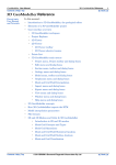
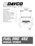
DaimlerChrysler Prop Rod Sponsor Paint Department Management Rudy Birney [email protected] Steve Kosc [email protected] Matt Savage [email protected] Tom Webster [email protected] Team 4 Rosemary Kowalski [email protected] Meghan O’Leary [email protected] Jason Reinhardt [email protected] Stephen M. Walls [email protected] Advisor Dr. Michael Keefe [email protected] Executive Summary A new redesigned Prop Rod is vital to provide improvements and to create a more efficient paint line at the Dodge Durango assembly plant. Team 4’s mission is to redesign the Rod, while satisfying the wants and constraints imposed by the paint department of DaimlerChrysler. To achieve these goals, Team 4 has complied a listing of the customers and their wants, prioritizing and ranking the results with the most important customer. From these results, a top ten list of wants was assembled, which were used in a wants to metrics cross correlation. With these new conclusions and those obtained through a comparative performance scale of benchmarking, Team 4 was capable of providing a concept evaluation and selection. The initial concept for the Prop Rod was a T-attachment with an angled solid bar. The Tattachment would provide a new method for attachment, which would eliminate the need for a hinge and also fulfill the want for no moving parts. This attachment in conjunction with an angled bar would allow the Liftgate to achieve all four necessary positions, while also being lighter than the current rod. As the design progressed, the rod became rounded, instead of angled. The two-curve design would allow the rod to reach the lower positions and not interfere with the floor of the Dodge Durango trunk area. The team scheduled to meet with the management of Chrysler and tool engineers to discuss the design before the prototype was machined. Taking into account that one thousand Prop Rods will be produced, several modifications were made to ease the manufacturing. The largest change was made to the actual rod. The manufacturing engineers felt that although the design was technically correct and would get the job done, the bending necessary to create the design would be excessive for the quantity of rods that needed to be produced. With that in mind, the team redesigned to produce a Prop Rod composed of a straight bar with the T-attachment. A straight Rod proved to be lighter and quicker to install than the old designs, and correctly realized the four positions. Slight modifications were then made to enhance the movement of the rod, such as decreasing the overall size and also rounding the edges of the disk of the T-attachment. Drawings were completed and resubmitted for machining. The second prototype proved to be a successful improvement over the first. The team’s second round of testing incorporated operators from the line whom provided feedback based on ergonomics, ease of use and overall pros and cons of the design. The testing also involved the Millwrights who provided us with comments ands suggestions based on a manufacturing/process point of view. Some of the various concerns and comments included a different fourth angle and safety concerns. Taking the testing into account, the team redesigned to create the final design prototype. It is similar to our second prototype with slight modifications. The full package is discussed in the report and drawing packages. Overall, team 4 was successful in creating a new design, which adhered to the wants and needs of Chrysler and the other customers. 2 Table of Contents Introduction ……………………………………………………………………………… Purpose ………………………………………………………………………….. Final Product ……………………………………………………………………. Report Plan ……………………………………………………………………… Project Description ………………………………………………………………………. Brief Overview ………………………………………………………………….. Mission ………………………………………………………………………….. Four Positions …………………………………………………………………... Key Word Definition ……………………………………………………………. Problem Statement ……………………………………………………………… Problem Importance …………………………………………………………….. Customers ……………………………………………………………………….. Critical Issues …………………………………………………………………… Start and Completion Dates …………………………………………………….. Design Process …………………………………………………………………………... Defining Customers …………………………………………………………….. Wants …………………………………………………………………………… Constraints ……………………………………………………………………… Metrics and Target Values ……………………………………………………… Benchmarking …………………………………………………………………... Initial Concept Generation and Selection ………………………………………. Criteria for Top Choice …………………………………………………………. Management …………………………………………………………………… Work Plan and Schedule ………………………………………………………... Budget …………………………………………………………………………... Final Product …………………………………………………………………………….. Concept …………………………………………………………………………. Analysis and Development Testing …………………………………………….. Test Results ……………………………………………………………………... Stresses ………………………………………………………………………….. Prototype ………………………………………………………………………... Manufacturing Redesign ………………………………………………………... Verification Testing ……………………………………………………………. Redesign ………………………………………………………………………… Verification of Redesign ………………………………………………………... Redesign II ……………………………………………………………………… Verification of Redesign II ……………………………………………………… Handoff and Recommendations …………………………………………………………. Appendix A: References Appendix B: Benchmarking Appendix C: Concepts Appendix D: UDesign Worksheets Appendix E: Calculations Appendix F: Drawing Packages Appendix G: Test Plans and Results Appendix H: Detailed Schedule Appendix I: Detailed Budget Appendix J: Hand-Off to Sponsor 4 4 4 4 4 4 5 5 7 7 7 8 8 8 9 9 10 11 11 13 13 14 15 15 16 17 17 17 18 18 18 19 19 19 19 20 20 20 3 Introduction Purpose This report presents the work performed by Team 4 in the design development of the Prop Rod for the senior design project sponsored by DaimlerChrysler. It documents the current work being done and the status of the project to date. It is intended to show a chronological progression of our design process. Our intended audience is DaimlerChrysler Employee’s, Paint Department Management including: Rudy Birney, Steve Kosc, Matt Savage, and Tom Webster; and the Senior Design Staff. The main points which will be covered in this report include: an introduction to the problem, the design development of the concept, a thorough analysis of the concept chosen and an overall evaluation of the final prototype, illustrating the application of the design to Chrysler’s wants, needs and metrics. A path forward is also included which will help to demonstrate Team 4’s understanding of the design to DaimlerChrysler’s business applications. Final Product After much testing and redesign, the final product was a modification of our first prototype. The complete drawings are found in Appendix F. It is a straight bar with a handle and T-attachment. Report Plan The basic structure of this report is to show the progression of our design. However, to make things clear to everyone involved, it has been broken into four sections: Project Description, Design Process, Final Product, and Hand-Off and Recommendations. Project Description will go more in depth on what the problem really is. Most of this information is what the DaimlerChrysler Paint Department came to us with. It contains information on the current prop rod, as well as what improvements they are looking for. The Design Process section will give a detailed description of how we came to our final design. The wants and metrics, concept generation, testing, management, scheduling and budget are covered here. The Final Product section will cover in detail the final design. This includes detailed information on the prototype, validating the prototype, redesign, and validating any redesigns. Hand-Off and Recommendations will cover the user’s manual, and how we intend to present our final product to our sponsors. This includes scale-up and production information. Project Description Brief Overview The DaimlerChrysler Newark Assembly Plant has produced over 7.5 million vehicles starting with tanks in the early 1950’s to the present Dodge Durango. The plant floor covers 3.4 million square feet over a 244 acre facility, and employs ~2500 employees. The plant is split into three main departments: Body, Paint, and Assembly. The Prop Rod project comes from the Paint Department. 4 Mission Team 4’s mission is to redesign the Prop Rod, while satisfying the wants and constraints imposed by the Paint Department of DaimlerChrysler. The purpose of the Prop Rod is to support the Liftgate of the Dodge Durango in four positions through the paint process applications. The four positions are shown in Figure 1a-d. These positions specified because of programmed robot arms that apply paint, and operators that need to seal areas of the rear cargo compartment. A redesigned Prop Rod is vital to provide improvements and to create a more efficient paint line. Four Positions There are four main positions that the Liftgate will be rotated through during the painting process. The first position is approximately twenty degrees above the horizontal, the origin being measured at the point of attachment. The positions then move downward, so that the fourth position would be located eighty degrees below the horizontal. Fig. 1-a First Position Fig. 1-b Second Position Fig. 1-c Third Position Fig. 1-d Fourth Position 5 At the Durango plant, the Prop Rod is installed after the Durango has been through the phosphate E-coat. The Rod is installed by one employee and placed in the second position. The Durango then travels in the second position along the paint line, allowing clearance for doorways. When the Durango reaches the sealer area of the plant, the Liftgate is hoisted into the first position. This position allows the paint line employees access to the trunk area, thus being able to apply sealer. After sealer, the Liftgate will be adjusted into the third position in preparation for the powder coat and also for transfer to the second floor of the paint line. After the powder coating, the Durango moves to the automated paint booth. In the booth, the Liftgate is adjusted multiple times to allow for the paint process application, both manually and by robotics. The positioning of the Liftgate is very important in the paint booth. The opening angle of the Liftgate must be accurate in order for the robot to work properly and the paint process to be efficient. The Liftgate will leave the booth in the fourth position. After painting, the Liftgate sees a minor adjustment into the third position at finesse, before it is removed at the end of the paint line. The fourth position will be discussed further in the Redesign II and Handoff sections, because it was a source of error for our design. When we originally talked to management and the operators on the line, we were told that the fourth position was much higher than what it really was. It was not until we brought the operators from the line that they informed us of this. Figure 2 shows what was originally given to us as the fourth position. Fig. 2 The “original” position four The current Prop Rod being used by the Paint Department is shown in Figure 2. It weighs 8 lbs. and is made of low-carbon steel from the Paint Department’s machine shop. This is a redesign from a previous 2-piece prop rod. Both designs use bolts to attach to the Liftgate. This is a problem because the rod collects paint during the process that causes the bolts to strip the threaded rear windshield wiper holes. This the progresses into a bigger problem further down the line in Assembly because they will have trouble attaching the rear windshield wipers. Since the rod collects paint during the paint process applications, after 2 – 3 times through the entire paint 6 line, it must be cleaned. If this is not done, paint chips could get onto the body of the Durango, causing more work to be done so that it can be buffed out. Fig. 3 DaimlerChrysler current Prop Rod (Not to scale) The Dynomac is a large sand bath, into which the Prop Rods are immersed. The sand is then heated to 1400°F for a period of one half hour and agitated. This process removes the paint buildup. Sand, like any dirt, is bad for the Paint Department environment. On the current Prop Rod, there is a hinge where the attachment and the rod meet. The moving parts and small voids created allow sand to get into the rod. Improvements have been made on the current hinge, but the ideal situation would be no moving parts, hence no hinge. Keyword Definition For clarification purposes, the following key words will be defined: Liftgate – back door of the Dodge Durango Prop Rod – a metal rod used to support the Liftgate Painting Process – various automated and manual operations requiring four Liftgate positions Problem Statement To support a load in four positions. Problem Importance This project was assigned to Team 4 by the Paint Department at DaimlerChrysler. Chrysler presently uses a Prop Rod, which has undergone multiple revisions over the years. A new redesigned Prop Rod is vital to provide improvements and to create a more efficient paint line. 7 Top issues relating to the Prop Rod are safety, elimination of damage to the Liftgate, and exclusion of contamination (dirt, paint chips, etc.) by engineering a new attachment with no moving parts. Customers Our customers are, in order of importance: • Paint Department Management • Employee Installing the Prop Rod • Paint Booth Adjustor • Worker Adjusting the Prop Rod • Employee Removing the Prop Rod • Cleaner • Machinist • DaimlerChrysler • Car Industry • Senior Design Staff The ranking of our customers becomes important later when we discuss the wants and the concept selection. Also, it should be noted, that the distinction was made between the Paint Booth Adjustor and the Worker Adjusting the Prop Rod because Paint Booth Adjustor must quickly move the Liftgate in one swift motion without touching the painted surface. Critical Issues Critical issues are those issues that would cause the team hardships and stumbling blocks while designing the Prop Rod. Damage to the Liftgate is a major critical issue associated with this project. Any dents caused to the Liftgate will cause that Durango body to be pulled off line. Also, any damage now could cause problems in Assembly. Another critical issue is to have no moving parts as was mentioned earlier. The current Prop Rod utilizes a bolted connection with a simple hinge joint. These moving parts allow for the possibility of dirt and paint buildup. If there are no moving parts, there is less chance of dirt and paint becoming attached to the rod and getting into the paint. The final critical issue deals with BASF testing. Depending on what material the team chooses to machine the Prop Rod out of, there exists a possibility for BASF testing. This is necessary to make sure that any material in the rod will not react with or contaminate the paint. If this should happen, the paint on the body of the Durango could be damaged. However, it was stated by the management, that if we used materials that were already approved, we could skip this testing. Testing would only be necessary in the case of exotic materials. For example, if the team has time, it is desired to consider coating for the Prop Rod, which will reduce cleaning cost and time. This paint resistant coating is considered to be a potential problem because it has the possibility of affecting the paint adhesiveness. Start and Completion Dates Our group started preparing for the project on August 28, 2001. We received our project on August 30, 2001, and the completion date is December 7, 2001. 8 Design Process The first thing that we did after receiving our project was to visit DaimlerChrysler Newark Assembly Plant to gather more information about the project and its problems. To get a better idea of how the Prop Rod had to perform, we walked the paint line and talked with various employees. The information in the sections concerning customers, wants, constraints, metrics, and target values came from these visits. All of the detailed information is found in the UDesign worksheets in Appendix D. Defining Customers Determining whom we were making this Prop Rod for was one of our first tasks. We have shown the rankings of these customers in Table 1. Our primary customers were our sponsors, the Paint Department Management consisting of Rudy, Steve, Matt and Tom. Our other immediate customers would be the employees who would handle the Prop Rod on the line. Although the Prop Rod was handled many times through the whole line, we determined three main customers: employee installing the rod, employee adjusting the rod and the paint booth adjustor. The reason for the distinction of the paint booth adjustor was clarified in the Project Description Section. The other two people in the Paint Department whom were impacted by the Prop Rod would be the cleaner and the machinist. Name Rudy Birney Employee Installing Prop Rod Paint Booth Adjustor Workers Adjusting Prop Rod Employee Removing Prop Rod Cleaner Machinist Daimler Chrysler Car Industry Dr. Keefe Organization Daimler Chrysler Rank 1 Daimler Chrysler 2 Daimler Chrysler 3 Daimler Chrysler 4 Daimler Chrysler 5 Daimler Chrysler Daimler Chrysler 6 7 8 9 University of Delaware 10 Table 1 Customer Ranking The other customers that we determined for the Prop Rod were outside the Paint Department. DaimlerChrysler as a whole would be one of our customers, because they would want a Prop Rod that would not affect the quality of their vehicles. The car industry is also a distant customer. If designed a certain way, it could be used in various vehicles, not just DaimlerChrysler’s Dodge Durango. Our final customer would then be the Senior Design Staff, because they want a good product to bring back sponsors for next year. 9 Wants The final list of wants, constraints, metrics, and target values came from a combination of things. When we went to visit DaimlerChrysler for the first time, we talked to the management and various people on the line. Since there are three shifts during the course of a day, it was hard to pinpoint a specific person as the one who installed the Prop Rod, etc. That is why we classified them generally and talked to at least two shifts. The results of these conversations are shown in Table 2. Rate of Importance User Friendly 20.24 Work with Current Line 17 Lightweight 15.16 Cost Effective 12.01 Paint Resistant 10.21 Quick Installation 5.26 No Moving Parts 5.05 New Attachment 4.5 Bulkiness/Overall Size 3.01 In-House Manufacture 2.33 Dirt Resistant 1.81 Ease of Adjustment 1.81 Fufill Req of Sr. Design 1.63 Wants Table 2 Top Customer Wants From this we determined that the top want was safety. After presenting this to the Paint Department Management, we found that it fit in with the theory of DaimlerChrysler as a company. However, to mold this to Senior Design, safety cannot be a want. We felt that implementing a want of User Friendly would cover the issue of safety, and Chrysler agreed with us. This chart was also developed in Phase 1. After presenting it at the Phase Review to the Paint Department Management, we had to reevaluate our wants. Doing so gave us a different ranking, shown in Table 3. Ranking 1 2 3 4 5 6 7 8 9 Want Description I mportance User Friendly Work with Current Line Lightweight Quick Installation No Moving Parts Cost Effective Bulkiness/Overall Size Manufacture In-house Fullfill Req. of Senior Design 21 18 15 14 13 7 4 3 2 Table 3 Finalized Top Customer Wants 10 As we expected from the beginning, a major want was for the Prop Rod to work with the current line. We were assured that some reprogramming could be done to the robots, but we felt that we would make changing the positions a last resort. Part of the benchmarking that we did was on paint resistant materials, however, this was not a high priority. We decided that we would look into this after we finalized the design of our Prop Rod. Constraints There are three main constraints that also must be considered in the design of the Prop Rod. The first constraint is the paint booth environment. Within this, there are three main points to be considered: positioning, heat resistance, and process friendly. The Liftgate must be able to obtain the four necessary opening angles. This allows for operators to access the trunk area during sealing, and avoids interference with the robots during painting. It also has to be heat resistant. During the paint process it has to withstand temperatures of up to 13008F. Last but not least, it must be process friendly. DaimlerChrysler does not want to add any additional manpower. The Prop Rod must work with the current line and robotic systems. While designing something that will be beneficial to DaimlerChrysler, we also have to take into consideration the operators that will be working with and around this Prop Rod. There are OSHA regulations that need to be followed. There are also ergonomic concerns. There cannot be the potential to have an operator injuring him or herself while working with the Prop Rod. Both of these are related to our top want, user friendly that deals with safety. The final constraint was also a critical issue, BASF testing. The paint booth environment cannot be contaminated. Thus, the team must verify that any material used is safe for the paint booth environment. Metrics and Target Values In order to evaluate our concepts, we determined a list of quantifiable metrics that matched up with our wants. Table 4 illustrates each of the top wants with its corresponding metric, target value and the origin of the target value. 11 Want Metric Target Value User Friendly OSHA Specifications Quick Installation Ergonomics Incident of Injury Noise Size/Dimensions Angles Weight Overall Size Time No Moving Parts Static 0 DOF Cost Effective Reduce Overall Size Cost Size Weight Yes/No ≈ $10.00 16 in x 54 in <8 lb. Yes Work with current line Lightweight Manufacture In-House 16 in x 54 in Liftgate 208 to -808 <8 lb. 16 in x 54 in <12 seconds Origin of Target Value OSHA/Chrysler Current Rod/OSHA Paint booth Robot Current Rod/OSHA Current Rod Installation Time Engineering Mechanics Current Prop Rod Current Rod/OSHA Union Millwrights Table 4 Correlation of Wants, Metrics, Target values and their origins. Again, using UDesign worksheets, we developed a list in rank of priority, of criteria to evaluate our concepts. Table 3 shows the top metrics and how they ranked. The complete worksheet is shown in Appendix D. Metrics Width Length Weight Strength of Material Incidence of Injury Installation Time Area of Part Noise Degree of Freedom Repostioning Time Cost per 1 Use Millage of Paint Adhearance Thickness of Prop Rod Manufacturing Time % 15 14 14 12 11 8 8 4 4 3 3 2 1 1 Target value <1 ft. < 5 ft. < 7 lbs > 35 ksi 1 injury/5 years <10 Sec < 250 square in. < 90 dB 0 or static < 2 sec. < $10 < 5 mils < .75 in < 30 min Obtained From Current Rod Current Rod Current Rod Eng. Mechanics Chrysler Current Rod Current Rod Chrysler Eng. Mechanics Chrysler Chrysler Chrysler Chrysler Chrysler Table 3 Prioritized Metrics Width and length turned out to be the top metrics for our design. What this correlated into was that it had to be able to place the Liftgate in the same positions. So if you took the current Prop Rod and formed a rectangle from the bottom to the top, these would be the dimensions. The strength of the material used and incidence of injury were also considered important. This went right along with the top want of safety. 12 Benchmarking After developing the list of customers and top wants, the next thing to do was benchmarking. This was to see if there were any part of the prop rod could be made from items already being manufactured. While doing this research, we came across three existing prop rods. Two of them were from the Paint Department that we were working with. One of these was the current one that they wanted us to redesign and was shown in Figure 2, the other was a two-piece rod, which was previously used by DaimlerChrysler-Newark. The remaining rods were from other DaimlerChrysler divisions, the Windsor Minivan and the Jeep Grand Cherokee SUV. However, since we broke the Prop Rod into three areas: attachment, hinge and rod, we also looked into various attachments and hinges. A more detailed discussion of our benchmarking is located in Appendix B. Initial Concept Generation and Selection To more effectively design the Prop Rod, the design itself was broken into three main areas. These areas are the attachment, the hinge and the rod. The top concept of each area would give us an ideal rod. Tables 4, 5, and 6 show the UDesign worksheet for each area, and how each concept ranked. A more detailed discussion of each of the concepts for each area can be found in Appendix C. Hinge Concepts Bench A B C Concept Descriptions Bolted Hinge No Hinge Ball and Socket Enclosed in Flexible Housing Spring Hinge Conceptual Solutions Hinges B A C 4.60 0.80 1.6 Table 4 Hinge concepts compared to current simple hinge. Attachment Concepts Concept Descriptions Bench D E F G Attachment Utilizing Two Bolts Spring Clamp Used in Woodworking Magnetic Disc T-Connector Attachment using the Liftgate Lock Housing Suction Cup Attachmnet D 3.20 Conceptual Solutions Attachments F E 2.00 4.00 G 0.80 Table 5 Attachment concepts compared to the current bolted attachment. 13 Rod Concepts Concept Descriptions Bench G H I Straight Rod with Square Secondary Arm Straight Rod with Curved Secondary Arm Curve Rod with Straight Secondary Arm Angled Rod with Straight Secondary Arm Conceptual Solutions Rods I H 4 5.2 J 7.6 Table 6 Rod concepts compared to current Prop Rod. Criteria for Top Choice For each area, the team rated the conceptual idea against the benchmark. The hinge concepts A, B, and C were ranked against the benchmark simple hinge. This method was repeated for the attachments and rods. The highest-ranking concept or benchmark in each area gave us the ideal rod that would fit the wants and constraints of DaimlerChrysler. The T-attachment, using the Liftgate lock housing (can), the elimination of the hinge, and an angled bar ranked the highest. 8.00 7.00 6.00 5.00 4.00 3.00 2.00 1.00 0.00 1 No Hinge Ball and Socket Enclosed in Flexible Housing Spring Hinge Spring Clamp Used in Woodworking Magnetic Disc T-Connector Attachment using the Liftgate Lock Housing Suction Cup Attachmnet Straight Rod with Curved Secondary Arm Curve Rod with Straight Secondary Arm Angled Rod with Straight Secondary Arm Current Rod Graph 1 Comparative Analysis of Concept Designs It is established that the T-attachment, and angled bar with no hinge still rank best. The graph more clearly illustrates this ranking. The first three bars, starting on the left of the bar graph, 14 relate to hinge concepts A, B, and C. the next four bars correspond to concept ideas D, E, F, and G of the attachment. Finally, the last four bars correspond to the concepts for the rod design. These top concepts, T-attachment, no hinge, and angled bar, will be the makeup of the initial design. The Team feels that the main focus should first be on design and engineering of the Tattachment. Then after the attachment is prototyped, the team would move onto completion of the rod. This approach was discussed with the Paint Department sponsors, and they agree with the plan of action. A more detailed discussion of each of the concepts for each area can be found in Appendix D. Management We worked as a team and the work was divided as evenly as possible. Each teammate contributed an equal amount of hours. We visited Chrysler often to do testing and validation, as well as get feedback. We kept our sponsors up to date with weekly emails. Figure 3 shows the management structure, with Dr. Keefe acting as an intermediate advisor. Rudy Birney Steve Kosc Matt Savage Tom Webster Paint Department Management Team 4 Fig. 3 Organizational Structure Work Plan and Schedule When the project was initiated, we came up with a schedule that would later be modified as the semester went on. The work plan was simple, we would complete a stage and then inform Chrysler of the results. The major dates are listed below in Table 8. A more detailed schedule can be found in Appendix H. 15 Task Mission Statement Problem Statement Wants and Customers Concept Generation Concept Selection Approval of Prototype Validation Redesign Validation Adjustments Hand-off to Sponsor Start Date 9-4-01 9-4-01 9-5-01 9-12-01 11-12-01 11-20-01 11-27-01 11-28-01 11-28-01 11-28-01 12-10-01 End Date 9-11-01 9-11-01 9-14-01 11-15-01 11-17-01 11-20-01 11-27-01 12-5-01 12-5-01 12-5-01 12-10-01 Table 7 Work schedule with major dates. Team Hours Total hours = 500 $35/hour Development Assembly 17% Validation 3% 4% 76% Conceptual Table 8 Project hours. Budget Material costs made the final project budget come to $493.08. Table 9 shows the division between the different stages our design. Overhead costs for this project can be ignored since they come out to only approximately $0.23. Taking that into consideration, the price per Prop Rod will come out to $54.27. A more detailed budget can be found in Appendix I. 16 Prototype Rod Prototype T-attachment 3% 12% 50% 35% Redesigned Prototype Rod Testing / Presentation Table 9 Project Budget Final Product Concept The concept chosen for the attachment design is the T-attachment. In order to design the attachment, the force acting upon the Prop Rod must first be calculated for. Analysis and Developmental Testing Impact Force Analysis In order to determine the maximum force acting upon the Prop Rod, two types of loading were considered. There is the loading due to the static weight of the Liftgate and the loading due to a dynamic impact of the Liftgate against the Prop Rod as it is moved through its required positions. Velocity Analysis The velocity of the Liftgate can be determined from the principle of conservation of energy. The law for conservation of energy states that when the mechanical energy of a system, in this case the Liftgate, is conserved, the total kinetic energy of the system can be related to the potential energy without consideration of in-between motion. Using this, we found a maximum impact force of 2,603 N. The full calculations and explanation are in Appendix E. Impact Time In order to solve for the impact force, the time of impact must be determined. A schematic of the test setup used to obtain the time variable is as follows: 17 A high-speed camera is used to video the impact observed when the Liftgate of the Durango is raised to the highest position and then released. Connected to the camera is a time generator analyzer that will provide a running time code. This time count in conjunction with the image will be recorded in a regular VCR and displayed on a monitor. Digital Camera TC Generator VCR Monitor Fig. 4 Schematic of experimental setup used to measure the time of impact Test Results The impact test provided impact times of 0.03 seconds. The time was used to determine the impact force. The data is shown in Appendix G. Stresses The T-attachment will encounter two forms of stress when under load. If the disk is modeled as a beam, the load applied will cause a moment, and form the governing equations that the sum of the moments must equal zero, an equal but opposite internal resisting moment will also occur. It is these moments that tend to bend the beam. The bending stress was found to be 36.6 Mpa. It is noted that this is the maximum bending stress. Shear stress will be occurring in the disk round juncture. An internal vertical shear force, V, will be present to maintain the connection. The shear stress present is 2.56 Mpa. Again this is the maximum. The equations for both forms of stress on the attachment are located in Appendix E. Prototype The initial design of the Prop Rod centered on the T-attachment. To complete the design of the Prop Rod, and thus achieve the desired positions for the Liftgate, a rod section, composed of ½” diameter low-carbon steel rod, following long sweeping curves was designed. The curves would allow the rod to reach the lower positions and not interfere with the floor of the Dodge Durango trunk area. In order to develop the lengths and angles of the rod necessary to realize the four positions, the rear floor of the Dodge Durango was created in AutoCAD 2002. The Liftgate was drawn in all four of the desired positions, using measurements taken by the team with the current Prop Rod installed. Our desired attachment point, the Liftgate Can, was then marked on the AutoCAD drawing. Using the lowest position of the Liftgate, the curvature of the lower arm was determined such that it would clear the first bump in the profile and contact the body in our desired location. Choosing a point on the lower arm to attach to, and then making the upper arm meet the desired contact location, created the second curvature. The drawings for this prototype are located in Appendix F. The cost per unit rod and for the entire project is located in Appendix I. 18 Manufacturing Redesign The initial prototype drawings were submitted to DaimlerChrysler for evaluation. The team then scheduled to meet with the management and tool engineers at Chrysler to discuss the design before machining began. Some modifications were to the design of the Prop Rod to ease the manufacturing. These revisions include: changing the rounded bar to a straight rod, making the disk on the T-attachment round and smaller in size, considering the use of tubing, and elimination of the throat cut on the T-attachment. The rounded bar was changed to a straight bar because of the fact that potentially one thousand Prop Rods will be produced. The straight bar only requires one length cut, versus the extensive bending that would be required with the rounded bar. The T-attachment disk will also be rounded to prevent damage to the Liftgate Can. The overall size was also reduced to decrease the weight. The throat cut was eliminated, for it was not necessary – it would actually increase the amount of welding needed. Finally, the tool engineers suggested the use of hollow stock in the design. This could further reduce the overall weight of the Prop Rod. The drawings for the manufacturing redesign are found in Appendix F. Verification Testing The modifications were made to the drawings and resubmitted to Chrysler for machining. Once the Prop Rod was manufactured, the Team tested the prototype. The Prop Rod was tested to ensure that it obtained the proper positions and angles necessary for the paint line. The Rod was installed, adjusted and removed, taking note of potential problems, damage, and improvements. Overall, the Prop Rod achieved all the necessary positions. Problem areas that need to be addressed include rotation of the bar during a change of position and damage to the paint on the Liftgate can. Redesign The rotation will be eliminated by decreasing the distance between the cross and the disk of the T-attachment from 1 ½ to 1 inch. Rounding over the edges of the disk will reduce the damage to the paint on the Can. The overall length of the Rod will also be shortened by three inches. This will enable all the necessary positions to be obtained, while allowing easier installation and operation. Verification of Redesign The second prototype proved to be a successful improvement over the first. The team’s second round of testing incorporated operators from the line whom provided feedback based on ergonomics, ease of use and overall pros and cons of the design. Overall the operators were very excited about the new Prop Rod and provided a great source of feedback. The installer and operators in the beginning of the line were really pleased with the new design. The installer especially liked the T-attachment, in that there were no bolts, so he felt it was safer in this aspect since there would be no shearing of the bolts. It was very user-friendly, 19 in that it was easy to install and adjust. It is also much quieter, because the T-attachment does not require any mechanical tools to install. However, he had some concern in that the rod might be too thin, a thicker material might be easier to grab onto and adjust. Our sponsors Steve and Matt also iterated this. Another operator, who is very petite, especially liked the Prop Rod design because it was lighter and easier for her to position the Liftgate. In addition to these operators, we also had the paint booth operators there to give us their feedback. Their job is a little different than the other operators, in the fact that the paint is wet over much of the Liftgate and rear cargo area. They have a small space about 1.5’ x1.5’ that they can touch near the base on the right and left sides of the Liftgate. Although we had talked to them before and asked them what types of things they would like to see in the Prop Rod, it was not until this verification that they actually informed us of some items. Since they have to quickly move the Liftgate from the third to fourth position, they lift the Liftgate by the small patch at the base, and let it fall down. Although our Prop Rod is designed to withstand the force of being dropped like that, we feel that to correctly achieve the fourth position that we had designed for, there must be a change in how this position is obtained. Please see the handoff section for a more in-depth discussion. The testing also involved the Millwrights who provided us with comments ands suggestions based on a manufacturing/process point of view. Some of the various concerns and comments included maybe making the rod out of a heavier stock. However, most of our verification was from the user standpoint. After we finished with the operators, we sat down with our sponsors Steve and Matt to discuss what was to be done now. Matt really expressed a concern over having the Prop Rod being made out of a wider stock. We explained that this would add to the bulkiness and add weight, something that Chrysler was trying to get away from. Their reasoning was safety and legal concerns. We suggested that instead of using low carbon steel, we might switch to higher strength steel so that not too much weight would be added. They seemed to accept this, but still wanted us to make modifications to the design before looking into changing the material. Redesign II Based on the input of the operators, changes were made to the Prop Rod design. These changes include incorporating a handle onto the Prop Rod for easier adjusting, while also reducing the overall size by two inches. The T-attachment was also reduced in size to further stabilize the rod. This is the rod that we are handing off to Chrysler with our recommendations. Final Design Our final design is a result of two redesigns and three prototypes. It is a straight bar with a handle and T-attachment. These changes have been discussed and the drawings can be seen in Appendix F. Handoff and Recommendation At the conclusion of our project, we have designed a final prototype Prop Rod that fulfills all of the original customer feasibility criteria. In getting to this final stage, we prototyped, redesigned, and tested a T-attachment and three complete Prop Rods. 20 It was not until the second prototype was tested that the paint booth adjustors felt that we had designed for the wrong fourth position. This was the first time that anyone had brought this to our attention. Paint Booth adjustors drop the Prop Rod arm underneath the bumper instead of placing it inside the trunk area as we had designed it for. Upon looking at pictures of both positions and analyzing geometry, it was determined that the opening angles were the same for both positions. Therefore, we recommend that DaimlerChrysler adopt a standardized method for the fourth position adjustment. Upon examination the team feels that there is no real benefit for placing the second arm of the current Prop Rod underneath the bumper. In fact, we feel that placing the second arm under the bumper causes more damage. There is a potential of damage to the Liftgate (dropping it from the first position) as well as damage to the rear bumper. The Prop Rod undergoes more stress being dropped like this, than if it was placed inside the rear trunk area. Also the Prop Rod has the potential to crack and eventually break and injure an operator or damage the vehicle. Therefore the handoff for this project is to keep the inside fourth position. This will require the possibility of retraining the Paint Booth adjustors to implement this fourth position. As mentioned above, we do not feel that any geometric changes are necessary to the Prop Rod. Instead the retraining would involve applying a new method of positioning the Prop Rod inside the trunk area without touching the paint. This could be achieved by demonstrating to the Paint Booth adjustors that by using the handle one the final design, that you can lift the Prop Rod and place it into the inner fourth position without touching the Liftgate. There would be no potential to touch the wet paint on the Liftgate. Although this change might take time for the adjustors to get used to, we feel that our Prop Rod design fits the needs and wants of DaimlerChrysler, while being safer to the operators and the Liftgate. 21 Appendix A References 22 The references that we used for this project are as follows: Matthews, Clifford. ASME Engineer's Data Book. New York: ASME Press, 2001 Cost Estimating: Christopher Pezzica Black & Decker Baltimore, MD Manufacturing: Machinists DaimlerChrysler Newark Plant Materials: Dr. Ian Hall Mechanical Engineering Department University of Delaware 23 Appendix B Benchmarking 24 Our group conducting benchmarking by searching the Internet, catalogs, and company references. We grouped our benchmarking into previous Prop Rods, materials, attachments, and hinges. Previous Prop Rods First DaimlerChrysler-Newark Prop Rod (Two-Piece Prop Rod) This was the Prop Rod that was used prior to the current one. It consisted of two pieces, one of which was bolted to the Liftgate. It was operator friendly, and many operators expressed this feeling when we spoke to them. Figures B-1 and B-2 show drawings of the Two-Piece Prop Rod. Fig. B-1 Two-Piece Prop Rod. 25 Fig. B-2 Another view of the Two-Piece Prop Rod. Current DaimlerChrysler-Newark Prop Rod This was our main benchmark, and the rod that we redesigned. It was a redesign of the two-piece Prop Rod. It is once piece and consists of an attachment, hinge and rod. The attachment is bolted onto the Liftgate at the threaded windshield wiper holes. Figure B-3 shows an isometric view of the current rod. Fig. B-3 Current Prop Rod 26 Windsor Minivan and Jeep Grand Cherokee The Windsor Minivan plant and the Jeep Grand Cherokee plant both had their own versions of a Prop Rod. Figure B-4 shows the Windsor Prop Rod. It looks similar to our Prop Rod design, except that there is a handle and it is made of thinner stock. Fig. B-4 Windsor Minivan Prop Rod. The Jeep Grand Cherokee Prop Rod is a single rod that does not move. It does not allow the Liftgate to be positioned, as Chrysler would like it. Therefore, we did not really consider the Jeep Prop Rod an option in this situation. Attachments Another area that we benchmarked was new attachments. This was because the bolted attachment was becoming unsafe when it got coated with paint. Although some attachments seemed like they would be excellent, most of them would not agree with the paint booth environment. The web pages below are where we got information on attachments. www.uwm.edu/Universityoutreach/catalog/ENG_Plastics/snapfit.shtml www.techstandards.co.uk/pages/plb_050.htm www.3m.com/profile/pressbox/mech.html www.bikelift.com/mag_beam_fittings.htm www.boltproducts.com/tinnpage.htm We also tried to design our own attachments. We brainstormed and recorded them in the Logbooks. Figure B-5 shows the magnet, suction cup, spring clamp, and rod attachments. Mechanics One are that we tried to benchmark, but did not go in depth was mechanics. The reasons being that the rods were breaking in the middle after going through a few cycles. The following web page was one that we explored is listed below. www.hanford.gov/lessons/sitell/funccats/mechanic.htm 27 Paint Resistant Materials In order to simplify the design and to also open more options as far as design was concerned, we decided to look into paint resistant materials. One thing that we did have to look out for though was that this would not cause the paint job to be ruined. However, it was determined that this would be the last item that we would be concerned with. The web pages below deal with paint resistant coatings. www.oberoncompany.com/OBEnglsh/SPHood.html www.maniaweb.com/pdf/EYESFACE.pdf 28 Appendix C Concepts 29 These are the concepts that the team came up with during the concept generation phase. They are broken up into hinge, attachment, and rod concepts. Hinge Concepts No Hinge When Chrysler presented us with the project, one of the main concerns was the dirt that was getting into the hinge and then into the paint line. After looking at the problem, we thought that the Prop Rod could actually be designed without any hinge. When we went though the evaluation, this would up being the best hinge and what we would incorporate in our design. Ball and Socket Enclosed in Flexible Housing This hinge looks similar to the joint in the human knee. One end is a rounded ball that fits into a rounded socket on another bar. To keep dirt from getting into it, there would be a flexible housing, possibly tubing, that would encase the hinge. Figure C-1 shows a conceptual picture of what the ball and socket hinge would look like. Fig. C-1 Ball and socket hinge (Not to scale) Spring Hinge The spring hinge would again separate the rod into two pieces. Flat, rectangular strips of springy steel would join them. This design would allow flexibility in the rod, but the current cleaning method would not affect it. Figure C-2 shows a side view of the proposed spring hinge. Fig. C-2 Spring hinge (not to scale) 30 Attachment Concepts Spring Clamp This spring clamp is the type that is used in woodworking. It would allow for a quick installation time and is very inexpensive. However, the problem that we foresaw was getting the clamp around the mounting position. Figure C-3 shows what the spring clamp attached to the Liftgate would look like. Fig. C-3 Spring clamp (not to scale) Magnetic Disc During our brainstorming we came up with a simple solution that uses magnets to attach the Prop Rod to the Liftgate. This would have an extremely quick installation time. However, there are several disadvantages to using a magnet. From what we could find, this would probably be a very expensive solution. There is also a question of the strength of the attachment and whether the magnet would slip. The magnet attachment is shown in Figure C-4. Fig. C-4 Magnetic disc (not to scale) T-connecter Attachment using Liftgate Lock Housing The T-attachment is a design of our own. Figure C-5 shows a 3-D rendering of the T-attachment. It would fit into the lock housing of the Liftgate. It would allow for quick installation and no hinge on the Prop Rod. However, there is a possibility of damage to the lock housing and a reduced life in the Prop Rod due to loading. 31 Fig. C-5 T-attachment (not to scale) Suction Cup The suction cup attachment also allows for quick installation. There was a question of whether there would be a hinge. Also, the suction cup might only work on flat nonporous surfaces. Figure C-6 shows a rendering of the suction cup attachment. Fig. C-6 Suction cup (not to scale) 32 Appendix D UDesign Worksheets 33 These are the initial customer data and wants forms that we did. After Phase 1, we had to redo the wants because there was a slight change. The finalized list is located after the first one. We did not have to redo the concept evaluation, since the change in wants did not really affect it. Customer Data and Wants Formulation Project Title: Diamler Chrysler Prop Rod To redesign the Prop Tool to support the Liftgate of the Dodge Durango during the paint process application, incorparating wants and constraints imposed by the Paint Department Mission Statement: Customer Information Rank=who is the most important customer? 10 0.45 Name Organization Rank 1st Want Work with Rudy Birney Daimler Chrysler 1 current line Employee Installing Daimler Chrysler Prop Rod Want Information Priority 0.25 0.15 2nd Want 3rd Want Cost Lightweight Effective Quick Installation/R New Attachment emoval 0.1 0.05 4th Want 5th Want Paint No Moving Parts Resistant 2 Safety Daimler Chrysler 3 Safety Lightweight Ease of Adjustment Workers Adjusting Daimler Chrysler Prop Rod 4 Safety Lightweight Bulkiness/Overall Size Bulkiness/Overall Size Quick Installation/R emoval Dirt Resistant Lightweight New Attachment Safety Paint Booth Adjustor Employee Removing Prop Rod Daimler Chrysler 5 Paint Resistant Lightweight Cleaner Daimler Chrysler 6 Paint Resistant Machinist Daimler Chrysler 7 In-House Manufacture Daimler Chrysler 8 Safety Car Industry 9 Cost Effective 10 Fufill Requirement of Senior Design Dr. Keefe University of Delaware No Moving Parts No Moving Parts Cost Effective New Attachment Partner Information Name Organization Steve Kosc Daimler Chrysler Matt Savage Daimler Chrysler Lightweight Dirt Resistant Bulkiness/Overall Size Bulkiness/Overall Size Work with current Line Paint Resistant No Moving Parts Lightweight Constraints 10 Rank 1st Allow Liftgate to Position at the Four Required Angles 2nd 3rd Withstand Temps of 400 deg F No Additional Manpower Required for Usage 34 Wants Score Safety 5.5804 Work with Current Line 4.6875 Lightweight 4.1806 Cost Effective 3.3125 Paint Resistant 2.8167 Quick Installation 1.4500 No Moving Parts 1.3849 New Attachment 1.2421 Bulkiness/Overall Size 0.8298 In-House Manufacture 0.6429 Dirt Resistant 0.5000 Ease of Adjustment 0.5000 Fufill Req of Sr. Design 0.4500 Total 27.5772 Rank 1 2 3 4 5 6 7 8 9 10 11 12 13 Rate of Importance 20.24 17 15.16 12.01 10.21 5.26 5.05 4.5 3.01 2.33 1.81 1.81 1.63 35 Appendix E Calculations 36 The calculations that we did were to find the maximum force and the stresses that the attachment and the Prop Rod would see. This was necessary in order to make sure that we designed the Prop Rod to stand up to everything. The data collected in order to finish the calculations is found in Appendix G. Velocity Analysis for Liftgate The velocity of the Liftgate can be determined from the principle of conservation of energy. The law for conservation of energy states that when the mechanical energy of a system, in this case the Liftgate, is conserved, the total kinetic energy of the system can be related to the potential energy without consideration of in-between motion. Thus, ∆PE = ∆KE 1 m ⋅ g (h1 − h2 ) = m (V22 − V12 ) 2 (1) If the motion of the Liftgate is compared to that of a simple pendulum, the Liftgate will start out with an initial velocity of zero. Here, at the highest position, the energy is strictly potential energy. As the Liftgate is released and dropped, the energy is being converted to kinetic energy where the Liftgate will gain speed and have the greatest velocity at the lowest point. In this system, the lowest point will be where the Liftgate contacts the back bumper of the car. Therefore, for the Liftgate system, m ⋅ g (h + R ⋅ sin θ1 ) − m ⋅ g (h − R ⋅ cos θ 2 ) = V2 = 2 ⋅ g ⋅ R (sin θ1 + cos θ 2 ) 1 m ⋅ V22 2 (2) m ⋅ V = Fimpact ⋅ timpact Fimpact = m 2 ⋅ g ⋅ R (sin θ1 + cos θ 2 ) timpact (3) Stresses The T-attachment will encounter two forms of stress when under load. If the disk is modeled as a beam, the load applied will cause a moment, and from the governing equations that the sum of the moments must equal zero, an equal but opposite internal resisting moment will also occur. It is these moments that tend to bend the beam. Shear stress will be occurring in the disk rod juncture. An internal vertical shear force, V, will be present to maintain the connection. Bending Stress due to Ring Loading 37 σ = 3 ⋅ Fimpact (1 − µ ) R 2 R 2 ln 2 2 π ⋅t r R −r (4) where t = thickness of the disk, R = outside diameter of the disk, r = inside diameter of the disk, and µ = Poisson’s ratio Shear Stress in the Disk/Rod Juncture V τ = , A = 2 ⋅ t ⋅π ⋅ r → τ = A Fimpact 2 2tπr (5) Maple Calculations restart: g:=9.81; g := 9.81 W:=155.6875; W := 155.6875 m:=W/g; m := 15.87028542 theta[1]:=3.14159/9; theta[2]:=3.14159/10; R:=.954532; m θ2 := .3141590000 R := .954532 t:=.03; F := θ1 := .3490655556 t := .03 2 g R ( sin( θ1 ) + cos( θ2 ) ) t F := 2603.276716 The maximum force acting on the attachment is 2603 Newtons, which corresponds to 585.2 lbs. F:=2603.3; F := 2603.3 Poisson's ration mu is .29 for steel; mu:=.29; 38 µ := .29 The outside radius of the disk is 0.0381 meters. R[o]:=.0381; Ro := .0381 The inside radius of the disk is 0.00635 meters. R[i]:=.00635; Ri := .00635 The thickness of the disk is .0127 meters. t[d]:=0.0127; td := .0127 The stress due to the ring loading of the disk is given by the following: 2 Ro Ro 3 F ( 1 + µ) 2 ln R 2 Ro − Ri i σd := 2 3.14159 td σd := .3664311624 10 8 evalf(%); .3664311624 10 8 The stress due to the ring loading is 36.6 MPa. The other area of concern is the shear stress in the attachment between the disk and the rod. tau:=V/A; V τ := A V:=F/2; V := 1301.650000 A:=t[d]*2*3.14159*R[i]; A := .0005067070511 tau:=V/A; τ := .2568841300 10 7 The shear stress due to the loading is then 2.56 MPa. 39 Appendix F Drawing Packages 40 41 42 43 44 45 46 47 48 49 Appendix G Test Plan 50 Testing Completed Test 1 Determine the impact time of the Liftgate when dropped from the highest position. Objective With the impact time we can determine the maximum force that the Liftgate would see when dropped from the highest position. The max force was used in the design of the attachment. This would be a worse case scenario, and would most likely only happen a few times in a shift. Equipment • • • • • High speed camera Time code generator VCR Small TV screen Tripod Procedure Since we were doing the test on the plant floor of Chrysler, our options of how to do testing were limited. That is why we decided to video tape the impacts. The procedure is as follows. 1) 2) 3) 4) 5) 6) 7) 8) First we set up our equipment. Figure G-1 shows a schematic of the equipment. The video camera was placed close to the bumper of the Durango so a good view of the impacts could be seen. We then let the video record for a short time without doing any tests, to make sure the setup was working. The time code generator displayed the time on the video so that when we went to play it back, getting the impact times would be easier. The Liftgate was then raised to the highest position and dropped. The impact was recorded on tape. 22 impacts were completed. Later the taped was viewed in slow motion and the impact times recorded. The average impact time was calculated and used to find the maximum force. 51 Data Angle 3 Angle 2 Angle 1 Impact Times Run / Trial Impact 1 1 0.030 2 0.020 3 0.020 4 0.035 5 0.025 6 0.040 7 0.035 8 0.025 9 0.020 10 0.030 11 0.030 12 0.025 13 0.030 14 0.035 15 0.035 16 0.020 17 0.030 18 0.025 19 0.030 20 0.040 21 0.035 22 0.030 0.029 Time (s) Impact 2 0.030 0.030 0.040 0.030 0.030 0.035 0.040 0.030 0.030 0.025 0.035 0.035 0.030 0.035 0.030 0.030 0.025 0.032 Impact 3 0.040 0.035 0.040 0.035 0.040 0.035 0.040 0.030 0.025 0.040 0.036 Avergage * Note: We are only concerned with the first impact for this test. Average Standard Variance Impact Deviation Time (s) 0.029 0.006229 0.0000370351 Conclusions and Recommendations Although the main reason from this test was to gather the impact time to use in our calculations, it also had another purpose. The Paint Department mentioned several times that one of our main concerns when designing the rod was that it could not damage the Liftgate. We had not actually seen how this damage occurred, or what the Liftgate looked like after this damage. After completing 22 trials, the Liftgate was damaged to the point where the impact times were not as reliable. We were able to tell this onsite because the gap between the Liftgate and the bumper had decreased considerably. We were interested in this because the damage looked to be in the area of the locking mechanism that we wanted to use for the attachment. After stopping the testing, we examined the locking mechanism area. The locking mechanism itself was not damaged or dented. However, the sheet metal around the mechanism, near the spot welds, was dented in. 52 We then talked to the Paint Department management, explaining to them that this was worse case scenario. After explaining the results of the test to them, they deemed that it wasn’t that serious. The Liftgate would probably not be dropped from that high of a position and hit the bumper. It might happen once or twice during the course of the day if the Liftgate slipped out of the hand of an operator. Therefore we can say, with the go ahead of the management, that placing the attachment here is ok. However, after testing the first Prop Rod on the line, it is recommended that the audit team look to verify that there is no unacceptable damage. Testing in Progress Test 2 Determine the reason the current Prop Rods were breaking in the center. (Materialography) Objective When we were talking to the operators on the line, the installer was showing us the Prop Rods that had to be pulled offline because something was wrong with them. About a third of them were broken in half. We are going to use Materialography to determine the cause. Conclusion and Recommendations The failure analysis concluded that the breaking of the rods were not due to any stresses that the rod was subjected too during the paint process, but the cleaning process. During the cleaning process, the rod is subjected to temperatures above the temperature at which phase transitions occur in the metal. This leads to a change in the structure of the steel on a microscopic level. This change causes thermal stress on the rods, which in turn leads to their failure. The only possible way to avoid this is to more closely determine the temperature required to remove the paint and not cause this phase transformation. However, if the paint is not removed at lower temperatures, and the higher temperature is then required, the rods will be stressed and fail. Validation Test 3 Determine how our Prop Rod design works. Objective We had a prototype of our initial design made up. Now we needed to verify that it would work as intended. If not, then we could make some changes. Equipment • • Redesigned Prop Rod One Durango Procedure 1) 2) 3) We attached the Prop Rod the Liftgate. Then we positioned the Liftgate in all four positions. We got Steve and Matt to look at it, and actually use it to get their opinion. 53 Conclusion and Recommendations After using completing this, we felt that it was actually worth pursuing this design. We found that the rod was 3 inches too long. Also, there was too much space between the disk on the attachment and the Liftgate. It was decided to decrease the space between the top of the attachment and the disk to ½ inch. Also, the short arm, we determined was no longer necessary. However we felt that we might shorten a little and move it closer to the attachment to use as a handle. Revalidation Test 4 Determine that the final redesign works as intended. Objective After performing the validation testing, we went back and made some changes to the design. Before handing it off to DaimlerChrysler, we wanted to verify that it worked as intended. Equipment • • Redesigned Prop Rod One Durango Procedure 1) We attached the Prop Rod to the Liftgate 2) Then we positioned the Liftgate in all four positions. 3) We had the Paint Department management and the operators there to give us input. Conclusions and Recommendations The recommendations for this are located in the report for Hand-off. 54 Appendix H Detailed Schedule 55 Appendix I Detailed Budget 56 The cost estimate is shown a few ways. First there is a list of all the costs associated with this project. It should be noted that no money actually was exchanged during this project. Second, there is a breakdown per phase on what was spent. Finally to show the cost to manufacture the rod, we figured a cost per rod for Chrysler. Detailed Cost Materials Unit Cost ($) Per Item Item Prototype T-attachment Prototype Prop Rod Redesigned Prototype Prop Rod Testing/Presentation Round Stock School Machine Shop Time Attachment Rod Chrysler Machine Shop Time Number Cost ($) of Items Charged to Incidentals ($) Cost to Sponsor ($) 2.50 / rod 1 2.50 2.50 25.00 / hour 0.5 12.50 12.50 2.50 10.00 / attachment / rod 1 1 2.50 10.00 2.50 10.00 44.27 / hour 1 44.27 44.27 Attachment 2.50 / attachment 3 7.50 7.50 Rod Chrysler Machine Shop Time 10.00 / rod 3 30.00 30.00 44.27 / hour 3 132.81 132.81 Liftgate 112.00 / Liftgate 2 224.00 Tape Poster 3.00 / tape 1 3.00 9.00 3.00 9.00 15.00 15.00 493.08 42.00 Posterboard 224.00 451.08 Totals Cost for Phase 2 Cost Estimate for Phase 2 Attachment Item Aluminum School Machine Shop Time Cost Per Unit 100 25 dollars/rod dollars/hour Total Cost ($) Unit 1 2 rod 100 hours 50 150 57 Cost Per Prop Rod Cost Estimate Per Rod Direct Labor Costs Per Unit Item School Machine Shop Time Chrysler Machine Shop Cost Per Unit Total ($ per prop rod) Unit 25.00 dollars/hour 0 hours 0.00 44.27 dollars/hour 1 hours 44.27 44.27 Total Direct Labor Costs Per Prop Rod Direct Material Costs Per Unit Item Aluminum/ Steel Cost Per Unit 10.00 Total ($ per prop rod) Unit dollars/rod 1 rod 10 10 Overhead Costs Per Unit Cost Per Unit Item Gate Tape Original Prop Rod for Materialog raphy Unit Total Direct Material Costs Per Prop Rod Total ($) 112.00 3.00 dollars/gate dollars/tape 2 1 gates tapes 224.00 3.00 10.00 dollars/rod 1 rods 10.00 237.00 Number of Prop Rods Produced Total Overhead Costs # Prop Rods Total Overhead Costs 1000 = Cost Per Prop Rod (with Overhead Costs) 54.507 Cost Per Prop Rod (without Overhead Costs) 54.27 0.237 58 Appendix J Hand-off to Sponsor 59 Instructions Insertion 1. Retrieve one Prop Rod. 2. Open Liftgate of Dodge Durango. 3. Locate Liftgate Can. 4. Insert Prop Rod T-attachment into slot in Liftgate Can. 5. Rotate Prop Rod 90°. 6. Prop Rod is now inserted. Adjustment 1. Remove pressure on Prop Rod by lifting Liftgate slightly. 2. Grab Prop Rod by handle. 3. Lift Liftgate by Prop Rod to desired position. 4. Lower Liftgate onto Prop Rod. Removal 1. Lift Liftgate and release pressure on the Prop Rod. 2. Rotate Prop Rod 90°. 3. Pull Prop Rod attachment out of slot in Liftgate Can. 4. Prop Rod is removed. 60