1
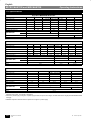
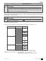
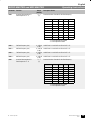
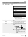
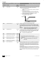
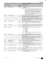
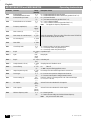
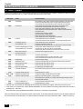
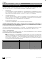
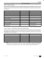
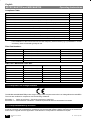
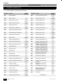
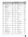
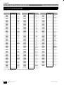
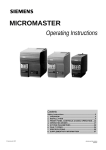
English Operating Instructions MICRO MASTER and MIDI MASTER Parameter Function Range [Default] P051 Selection control function, DIN1 (terminal 8), fixed frequency 5. 0 – 18 [1] P052 Selection control function, DIN2 (terminal 9), fixed frequency 4 0 – 18 [2] P053 Selection control function, DIN3 (terminal 10), fixed frequency 3. If set to 17, this enables the most significant bit of the 3–bit BCD (see table). 0 – 18 [6] P054 Selection control function, DIN4 (terminal 11), fixed frequency 2. If set to 17, this enables the middle bit of the 3–bit BCD (see table). 0 – 18 [6] P055 Selection control function, DIN5 (terminal 12), fixed frequency 1. If set to 17, this enables the least significant bit of the 3–bit BCD (see table). 0 – 18 [6] Description / Notes Value Function of P051 to P055 0 1 2 3 4 5 6 7 8 9 10 Input disabled ON right ON left Reverse OFF2 OFF3 Fixed frequencies 1 – 5 Jog right Jog left Remote operation Fault code reset 11 12 13 Increase frequency * Decrease frequency * Disable analogue input (setpoint is 0.0 Hz) Disable ‘P’ button Enable dc brake Use jog ramp times instead of normal ramp times Binary fixed frequency control (fixed frequencies 1 – 8) ** As 6, but input high will also request RUN 14 15 16 17 18 Function, low state – Off Off Normal OFF2 OFF3 Off Off Off Local Off Off Function, high state – On right On left Reverse On On On Jog right Jog left Remote Reset on rising edge Increase Decrease Analogue disabled ‘P’ disabled Brake on Jog ramp times On Off On Off Off Analogue on ‘P’ enabled Off Normal * Only effective when P007 = 0. ** Not available on P051 or P052. Binary Coded Fixed Frequency Mapping DIN3 (P053) DIN4 (P054) DIN5 (P055) FF5 (P046) 0 0 0 FF6 (P047) 0 0 1 FF7 (P048) 0 1 0 FF8 (P049) 0 1 1 FF1 (P041) 1 0 0 FF2 (P042) 1 0 1 FF3 (P043) 1 1 0 FF4 (P044) 1 1 1 Note: If P051 or P052 = 6 or 18 while P053 or P054 or P055 = 17 then the setpoints are added. Examples: (1) P053 = 17, P054 = 17, P055 = 17: All 8 fixed frequencies are available e.g. DIN3 = 1, DIN4 = 1, DIN5 = 0 ⇒ FF3 (P043) (2) P053 < 17, P054 = 17, P055 = 17: DIN3 is fixed at zero (only FF5 to 8 available) e.g. DIN4 = 1, DIN5 = 0 ⇒ FF7 (P048) P056 36 Digital input debounce time G85139–E1720–U325–B 07.96 0–2 [0] 0 = 12.5 ms 1 = 7.5 ms 2 = 2.5 ms The response time to a digital input = (debounce time + 7.5 ms). Siemens plc 1996