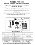
1
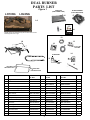
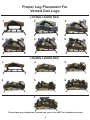
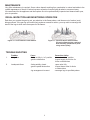
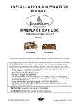
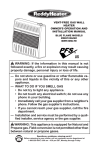
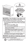
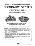
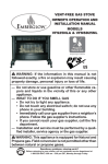
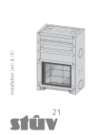
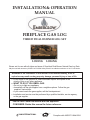
INSTALLATION & OPERATION
MANUAL
FIREPLACE GAS LOG
TIERED DUAL BURNER LOG SET
LO18NG
LO24NG
Burner set for use with all styles and sizes of SureHeat Dual Burner Natural Gas Log Sets.
May be used with accessory CVS303 or RVS304 Safety Pilot Kit for added convenience or for LP conversion.
WARNING:If the information in this manual is not followed exactly, a fire or
explosion may result causing property damage, personal injury or loss of life.
— Do not store or use gasoline or other flammable vapors and liquids in the
vicinity of this or any other appliance.
— WHAT TO DO IF YOU SMELL GAS
• Do not try to light any appliance
• Immediatly call the gas supplier from a neighbors phone. Follow the gas
supplier’s instructions.
• If you cannot reach the gas supplier, call the fire department.
— Installation and service must be performed by a qualified installer, service agency,
or the gas supplier.
INSTALLER: Leave this manual with the appliance.
CONSUMER: Retain this manual for future reference.
Listed By
Portland
Oregon USA
C SHM INTERNATIONAL
OMNI- Test Laboratores, Inc.
Complies with ANSI Z21-84b-2004
DUAL BURNER
PARTS LIST
Figure 1
LO18NG
GRANULES
(HEAVY WEIGHT BAG)
LO24NG
GLOWING EMBERS
(LIGHT WEIGHT BAG)
16
17
1-6
INSTALLATION & OPERATION
MANUAL
FIREPLACE GAS LOG
TIERED DUAL BURNER LOG SET
CCF18NG
CCF24NG
Burner set for use with all styles and sizes of SureHeat Dual Burner Natural Gas Log Sets.
19
May be used with accessory CVS 303 or RV S304 Safety Pilot Kit for added convenience or for LP conversion.
WARNING:If the information in this manual is not followed exactly, a fire or
explosion may result causing property damage, personal injury or loss of life.
— Do not store or use gasoline or other flammable vapors and liquids in the
vicinity of this or any other appliance.
— WHAT TO DO IF YOU SMELL GAS
• Do not try to light any appliance
• Immediatly call the gas supplier from a neighbors phone. Follow the gas
21
supplier’s instructions.
• If you cannot reach the gas supplier, call the fire department.
— Installation and service must be performed by a qualified installer, service agency,
or the gas supplier.
Number of logs are determined by the size and model chosen.
Sets range from 6 to 7 logs.
INSTALLER: Leave this manual with the appliance.
CONSUMER: Retain this manual for future reference.
Listed By
Portland
Oregon USA
C SHM INTERNATIONAL 2011
Complies with ANSI Z21-84b-2004
OMNI- Test Laboratores, Inc.
12
18
13
10
21
7
14
FLARED END
9
TO 1/2" NPT
GASLINE
11
TO
BURNER
BAR
8
LEFT SIDE
KNOCKOUT PLUG
15
RIGHT SIDE
KNOCKOUT PLUG
REF.
DESCRIPTION
PART NUMBER
18" SET
QTY. PART NUMBER
24" SET
1-6
Logs
—
—
7
Grate
RCORJ00003A
—
1
RCORJ00004A
QTY.
PART NUMBER
30" SET
QTY.
—
—
—
1
RCORJ00013A
1
8
Burner Pan
SBNCJ00365A
1
SBNCJ00367A
1
SBNCJ00366A
1
9
Dual Burner Bar
RC0CB00002A
1
RC0CB00003A
1
RC0CB00004A
1
10
3/4" Burner Support Spacer
RMH-120-00420
1
RMH-120-00420
1
RMH-120-00420
1
11
3/8" Brass Orifice Elbow
WIP-120-00350
1
WIP-120-00350
1
WIP-120-0035
1
12
3/8" Locknut
RMH-120-00963
1
RMH-120-00963
1
RMH-120-00963
1
13
3/8" Flare to 1/2" Gas Inlet Fitting R MH-120-00653
1
RMH-120-00653
1
RMH-120-00653
1
14
Damper Stop Clamp
RMH-120-00100
1
RMH-120-00100
1
RMH-120-00100
1
15
3/8" Flared Tubing
KHH-ACT16
1
KHH-ACT16
1
KHH-ACT16
1
16
Granules
WIP-130-00010
1
WIP-130-00010
1
WIP-130-00010
2
17
Glowing Embers
WIP-130-00300
1
WIP-130-00300
1
WIP-130-00300
2
18
Back Log Standoffs
SPSCJ00106A
2
SPSCJ00106A
2
SPSCJ00106A
2
19
Thread Sealant
RCSZZ00008A
1
RCSZZ00008A
1
RCSZZ00008A
1
20
Instruction Manual
R84026CC
1
R84026CC
1
R84026CC
1
21
Washer
RCODZ00145A
1
RCODZ00145A
1
RCODZ00145A
1
2
WARNING: Improper use or installation may cause Carbon Monoxide Poisoning. Carbon Monoxide,
is an colorless and odorless gas, and is a by- product of combustion. Caution must be taken to insure
thefireplace is properly vented when logs are in use To
. avoid having potentially dangerous fumes enter
the living area, be sure the chimney is drawing pro perly and has sufficient draft.
WARNING: Do not burn wood, solid fuels, or other material in any fireplace fitted with a gas log set.
Do not store gasoline ammable vapors and liquids in the vicinity of this or any other appliance.
Do not place clothing or other flammable material on or near the appliance.
Children and adults should be alearted to the hazards of high surface temperature and should
be kept clear to avoid burns or clothing ignition.
Young children should be carefully supervised when they are in the same room as the appliance.
Do not use this appliance if any part has been under water. Immediately call a qualified service
technician to inspect the appliance and to replace any part of the control system and any gas
control which has been under water.
A fireplace screen must be in place when appliance is operating. Unless other provisions are
made for combustion air, the fireplace screen must have provisions for combustion air.
Installation of this Energy Efficient Gas Log Set and provisions for combustion and ventilation air
must conform with the National Fuel Gas Code ANSI Z223.1/NFPA54, and any local codes.
This gas log set is only to be installed and burned in a fully vented fireplace with a fully functional
damper and chimney that is free of any obstructions. The fireplace must be constructed of noncombustible materials and approved to burn wood.
To operate this gas log set, the fireplace damper must be fully opened and
d locked.
The smallest or minimum dimension of the chimney flue must be 8 inches in diameter . Do not use an
Energy efficient Gas Log Set if it is smaller than 8 inches. Do not use an Energy Efficient Gas Log Set if
fumes from the burner emerge into the room when the damper is fully open. This indicates that there is
not adequate draft for this log set and it must not be used until the fireplace draft is corrected.
This appliance must be installed with a Damper Stop Clamp (Part #14). When operating this gas log set,
the flue damper must be fully open.
The nominal inlet gas pressure for this appliance i s 7” water column for natural gas.
This appliance must also be disconnected from the gas supply system by closing its individual manual
shutoff valve during any pressure testing at pressure equal to or less than 1/2 PSIG.
FIREPLACE PREPERATION
For installation in wood-burning fireplaces only. Keep damper wide open when in use. The appliance must be installed
with damper stop clamp. Minimum size chimney flue must
be 8"with a 6" stack. (See installation instructions for further
reference to stack height and appliancedimensions).
A. Professionally clean chimney and fireplace floor of any.
combustible material to limit the smell from the system
B. Open fireplace damper fully and install Damper Stop
Clamp with 1/4x2” set screw (Part 14#). This clamp is
Designed to allow any pilot combustion by-products to
vent (See Fig.2) Should the Damper Stop Clamp supplied not fit, a permenant damper stop clamp must be
installed that will keep the damper open at a distance of
not less than 1 1/2”.
The damper must be in the fully open position anytime
the unit is in operation.
C. Prior to connecting the gas log set, make sure that the
gas supply to the fireplace is completely shut off.
3
PART NO. 14
PREFABRIC ATED
FIREPLACE
Figure 2. Damper stop clamp
MASONRY
FIREPLACE
D. Prefabricated fireplace: Refer to the manufactures fireplace instruction manual for specific
information regarding the running of a gas line into that particular model. A typical installation
involves the insertion of a 1/2 inch gas pipe through the gas line tube provided by the manufacturer from outside the fireplace. The Knockout on the inside of the fireplace is removed
as the gas pipe is punched through the fireplace. (See Figure 3).
E. Masonry fireplace: A 1/2 inch gas supply line must be provided to the firebox. Most installations require drilling an access hole through the masonry wall. The supply line should be
secured and sealed by mortar within the access hole. The supply line should also have a
shutoff valve either in the wall or inside the fireplace (see Figure 4).
.
Figu r e 3. Gas line installation - Prefabricated Fireplace
Figure 4. Gas line installation - Masonry Fireplace
GAS LOG INSTALLATION
MINIMUM FIREPLACE SIZE
Siz e
18
24
Depth
12"
14"
Height
20"
24"
Width
20"
25"
NG-BTU
50,000
60,000
(See Figure 1 Parts List as a guide to reference part numbers.)
BURNER PAN INSTALLATION
NOTE: Use pipe compound on all male threads to seal join ts.
A. Determine if th
eplace has a right or left hand gas line feed.
The circular “Dimpled” hole covering must be knocked out on
the appropriate side (right or left) of the burner pan.
NOTE: Brace pan on workbench when removing burner
knock-out. Strike knock-out plug with a punch or drift.
B. Locate 3/8” locknut (Part #12) and washer (Part #21), and
attach them to the 3/8” brass ori fice elbow (Part #11) Do
not fasten the locknut on the “ flared” end.
C. Slide the 3/4” burner support spacer (Part # 10) over the
Dual Burner bar (Part #9) and move spacer to opposite
side of the gas inlet connection (See Figure 5).
D. Secure the intake end of the Dual burner bar (Part # 9)
to the burner pan (Part # 8) through the knock-out hole
selected (right or left hand) with the 3/8” brass orifice
elbow (Part # 11),3/8” locknut (Part # 12), and washer
(Part #21) previously assembled in Step B (See Figure 6).
E. T ighten elbow until firmly attached to the Dual burner bar.
Then, firmly tighten the attached lock-nut on the elbow to
seal the burner bar to the wall of the burner pan.
4
Figure 5. Burner bar placement
Figure 6. Burner bar connection
CONNECTING GAS SUPPLY TO BURNER ASSEMBLY
Natural Gas applications installed without a Safety Pilot Ki t. LP/NG Safety Pilot Kit available at your local store.
(If a Safety Pilot Kit is to be used, please refer to seperate instructions included with the kit.)
A. Place burner pan assembly in the center of the fireplace.
B. Attach 3/8” Flare X 1/2” NPT gas valve (Part #13) to the 1/2 inch gas supply stub already in fireplace.
Be certain connections are tight and use pipe compound on all male NPT (pipe) threads to seal
joints.
C. Attach 3/8” flared tubing (Part #15) to burner pan assembly.
.
Attach opposite end to gas supply line by
carefully bending the flared tubing as needed to make the connection. Avoid kinking the tubing while
bending. If tubing must be cut, use a tubing cutter. Flare the cut end of tube with a flaring tool.
NOTE: A good method of bending the tube is to fill it with sand, bending the tube as needed to make the
connection.This method will eliminate kinking in the line. Once the tube is in the desired configuration,
be sure to empty the tube completely of any sand before tube is connected to the gas supply line and
burner assembly.
D . Be certain all connections are tight. Only use pipe compound on all male NPT (pipe) threads.
Test all connections with a soapy water solution, and with the gas supply turned on. If bubbles appear
on any connection, tighten and re-test. Once it is determined there are no leaks whatsoever, turn off
gas supply and move to next assembly step.
GRANULE, EMBER AND GRATE PLACEMENT
A. Spread granules (Part # 16) over the installed burner pan. Granules
should be sloped to the same angle as the burner pan filling the entire
pan. (See Figure 7A.)
B. Spread glowing embers (Part # 17) evenly over the top of the granules
covering the entire surface area, concentrating on the front and sides
of the burner pan for the most realistic burning effect.
C. Place log grate (Part # 7) over the burner pan aligning as shown.
(See Figure 7B.)
D. Attach back log Standoff (Part # 18) to the back part of the grate.
(See Figure 7B.)
Figure 7 ( A & B) Granule and
Grate Placement
NOTE: A hammer may be used to tap the back log stand-off in place.
It may be necessary to squeeze the back log stand-off with pliers after
attaching to the grate.
WARNING: For installation in a solid-fuel burning fireplace only. The
fireplace chimney m ust have a permanent vent opening to atmosphere
of not less than 49.2 square inches, or as determined from the
manufacturer's installation instructions.
LIGHTING YOUR GAS LOG SET
Figure 8. Lighting the log set
(Manual Valve / match lit only)
A. Open chimney flue damper to the full open position.
B. Turn the gas control manual valve (Figure 9)clockwise
to the full
OFF position.
C. Wait five (5) minutes to clear out any gas. If you then smell gas, STOP!
Follow “A” in the safety Information above on this label. If you don't smell
gas, go to the next step.
D. Place a burning match on the surface of the burner embers (see figure 8)
. Do not hold match in hand.Turn the manual gas valve counterclockwise
to the ON position.
TO TURN OFF GAS TO APPLIANCE
Turn the manual gas control valve (Figure 9) clockwise
5
to the OFF position.
Figure 9. Manual gas valve
Proper Log Placement For
Vented Gas Logs
1
4
LO18NG LANIER OAK
2
5
3
6
LO24NG LANIER OAK
1
2
3
4
5
6
7
If you have any questions, please call (800) 229-5647 for customer service.
6
MAINTENANCE
Very little maintenance is required. Some carbon deposit resulting from combustion is natural and adds to the
realistic appearance of the set. If carbon becomes excessive it can be lightly brushed or vacuumed away.
We recommend for the appliance and the fireplace flue to be professionally inspected and cleaned each year,
prior to operation.
VISUAL INSPECTION AND MONITORING OPERATION
Each time you operate the gas log set, pay attention to the flame pattern, and the amount of carbon (soot)
being produced. If the gas log set continuously produces excessive carbon, you may wish to rearrange the
stack of the logs to allow more free space for the flames.
Figure 10 - Correct Burner Flame Pattern
Figure 11 - Incorrect Burner Flame Pattern
(Excessive flame height, combined
with extremely yellow flames producing carbon (soot)).
TROUBLE SHOOTING
1.
Problem
No Ignition
Cause
-Valve not fully in “on” position
-gas line obstruction
2.
Inadequate flame
-Valve partially closed
-gas line partial obstruction
-log arrangement incorrect
7
Corrective Action
-turn valve to “on” position
-inspect supply lines/ tube for
kinks or obstructions
-open valve fully
-inspect burner tube for kinks
or obstructions
-rearrange logs to specified pattern
LIMITED WARRANTY
Warranty shall apply to the original purchaser at the original installation point only.
All logs are guaranteed for three years against manufacturer’s defects.
The burner assembly system is guaranteed for a period of (3) years from the date of purchase and will be replaced
for freight costs only.
Pilot, valves and thermocouples are guaranteed for a period of one(1) year under the original manufacturers
warranty.
General Warranty: This warranty does not apply in the case of improper installation, neglect, accident.
misuse or as a result of modifications of the original product.
All costs for removal and re-installation are the expressed responsibility of the purchaser.
For repair, replacement, or service to defective part(s) please contact our Customer Service Hotline, number below.
Thereafter with valid warranty registration and proof of purchase, call the Customer Service Hotline for authorization
to ship defective part prepaid and insured in original carton to Sure Heat Manufacturing.
3140 Moon Station Road, Kennesaw GA 30144. Goods returned improperly packaged are the sole responsibility of
purchaser.
It is agreed that any repair or replacement is the exclusive remedy from Sure Heat Manufacturing. In no case shall
Sure Heat be liable for any consequential damage or breach of this or any other warranty expressed or implied
whatsoever. This limitation as to consequential damages shall not apply in states where prohibited.
Purchased From:
Size:
18"
Name:
Address:
City:
Date:
24"
30"
Model:
Phone:
State:
Zip:
Please photocopy and return to SHM International within 14 days of purchase.
If you have other questions, please contact the Customer Service Hotline - (800) 229-5647
R84026LO
Rev. 06/23/2014