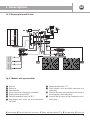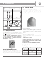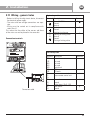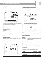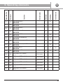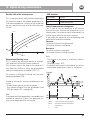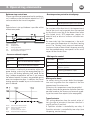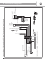
1
RC FH
GB
Installation and user manual / 01
GB
Thank you for your choice of ELECTRONIC CLIMATIC ADJUSTMENT KIT RC FH. Carefully read this manual
which contains the specifications and all useful information for correct operation of Thank you for your
choice of the ELECTRONIC CLIMATIC ADJUSTMENT KIT RC FH.
Index - ELECTRONIC CLIMATIC ADJUSTMENT KIT RC FH
GB
1 Description ..................4
3.2.1 Instructions for use Control unit................. 23
1.1 Function ............................................................ 4
3.2.2 Instructions for use Room remote control . 26
1.2 Fields of use .................................................... 4
3.3
1.3 Kit composition ................................................. 4
3.3.1 General rules .................................................. 27
1.4
Application diagrams ........................................ 5
3.3.2 Setting date and time ..................................... 27
1.4.1 Thermoregulation with mixing valve and
servo-control ...................................................... 5
3.3.3 User levels....................................................... 30
3.4
Programming of heating hours .................... 31
1.4.2 Thermoregulation with Floor Control Unit ............6
3.5
Display of parameters ................................. 32
1.4.3 Thermoregulation with Firstbox ......................... 7
3.6
Detail of parameters ................................... 44
2 Installation .................9
2.1
Three-way mixer valve .................................. 9
2.2
Servo-control .................................................. 9
2.3
Flow probe..................................................... 10
2.4
Flow probe on Floor Controlbox ................ 10
2.5
Flow probe on Firstbox ................................ 10
2.6
Safety thermostat ...................................... 11
2.7
External sensor ............................................. 11
2.8
Room remote control ................................... 13
2.9
Climatic adjustment device RC FH ............ 13
2.10 Control unit.................................................... 16
2.11 Wiring - General rules................................. 17
3 Operating elements ....19
3.1
Commissioning ............................................. 19
3.1.1 Control Unit ..................................................... 19
3.1.2 Getting Started............................................... 19
3.1.3 Language setting............................................. 19
3.1.4 Functional checks ............................................ 20
3.2
Methods of use ............................................ 23
Programming ................................................. 27
3.6.1 Date and time.................................................. 44
3.6.2 Control unit.................................................... 44
3.6.3 Programming ................................................. 45
3.6.4 Heating circuit .............................................. 45
3.6.5 Configuration ................................................ 53
3.6.6 LPB system..................................................... 55
3.6.7 Errors .............................................................. 58
3.6.8 Maintenance / Service................................ 58
3.6.9 Inputs/outputs test ...................................... 59
3.6.10 System status ............................................... 59
3.6.11 Diagnostics consumers ............................... 59
3.6.12 List of displays ............................................ 60
3.7
Adjustment and balancing of the system...... 62
3.8
Protective functions of the system ........... 62
3.9
Operating anomalies ................................... 63
4 Interface LPB Open
Therm ......................64
4.1
Instructions for installation and use
5 Connection diagrams .... 66
3
GB
1. Description
1.1 Function
The adjustment device managers a heating circuit controlled by a three-way mixer valve and circulator pump.
1.2 Fields of use
Residential and non-residential buildings, with floor heating, radiators, fan coils.
1.3 Kit composition
The kit is composed of the following components:
a) Control unit
b) Climatic adjustment device RC FH
RVS46.530/109
060706A
000020
S060706000020
1PRVS46.530/109
c) External probe
d) Remote control with room sensor
e) Flow sensor
f) Connectors kit
Mixing valve is not supplied. It should be selected according to the plant features.
4
GB
1. Description
1.4 Application diagrams
1.4.1 Thermoregulation with mixing valve and servo-control
/
Floor heated zone
Radiator heated zone
#
"
!
RVS46.530/109
$
060706A
000020
S060706000020
1PRVS46.530/109
%
&
'
'
(
)
*
-
+
.
,
Fig. 1
!
"
#
$
%
&
'
(
Control unit
Climatic adjustment device RC FH
External probe
Remote control with room sensor
Flow sensor with well
Safety thermostat
Servo-control for mixer valve
3-way mixer valve
)
*
+
,
.
/
Circulator pump
By-pass calibration lockschield
Non-return valve
Main manifold
Hydraulic separator
Boiler
Overpressure valve
5
GB
1. Description
1.4.2 Thermoregulation with Floor Control Unit
U
RVS46.530/109
060706A
000020
S060706000020
1PRVS46.530/109
"
M!
Fig. 2
" Flow bar for floor heating plant with regulation
lockshields
# Flow bar for radiator heating plant
$ Return bar set up to take thermoelectric heads
(radiator plant)
% Return bar set up to take thermoelectric heads
(floor plant)
& Boiler
' Servo-control and adjustment valve
( Setting and by-pass valve
) Circulator pump
* Flow pipe probe
+ Control thermometers from 0 to 80 °C
, Safety thermostat in box and electrical connection
to the circulator pump
- Overpressure valve (from 0,1 to 0,5 bar)
. Cut-off and balancing lockshield
/ Automatic air bleed valves 1/2’
0 Drain bibcocks with adjustable connection and
safety plug
1 Pump isolator ball valves
2 Kit valvole con by-pass
A External probe - B Remote control with room sensor - C Climatic adjustment device RC FH - U Control unit
6
GB
1. Description
1.4.3 Thermoregulation with Firstbox
U
!
RVS46.530/109
060706A
000020
S060706000020
1PRVS46.530/109
D
MIX
H
M
!
C
Fig. 3 - Modules whit open manifolds
"
#
$
%
&
'
(
Flow bar
Return bar
Open manifold
3-way mixer valve with electric servomotor
Shark circulator pump N 6/53
Control thermometers from 0 to 80 °C
Adjustment/cut-off valves set up for electrothermal heads
) Automatic bleed valves 1/2’
* Drain bibcocks with adjustable connection and
safety plug
+ Electrical box with safety thermostat for wiring of
low temperature circulation pump
, Electrical box for wiring of high temperature circulation pump
A External probe - B Remote control with room sensor - C Climatic adjustment device RC FH - D Flow pipe probe - U Control unit
7
GB
1. Description
Descrizione
U
#
RVS46.530/109
060706A
000020
S060706000020
$
1PRVS46.530/109
"
D
MIX
H
M
!
C
"
%
Fig. 4 - Modules for low-temperature heating system with auxiliary connections for high-temperature terminals
"
#
$
%
Flow bar
Return bar
3-way mixer valve with electric servomotor
Shark circulator pump N 6/53 cabled
& Control thermometers
' Electrical box with safety thermostat for wiring of
low temperature circulation pump
( Progress valves kit (optional)
A External probe - B Remote control with room sensor - C Climatic adjustment device RC FH - D Flow pipe probe - U Control unit
8
GB
2. Installation
2.1 Three-way mixer valve
Mixture takes place through ways A and B towards
AB.
A
Assembly
Assembly of the valve and servo-motor is easy, since
special tools or travel calibration are not required.
During installation, carefully note the symbol of the
direction of flow of the valve:
Mixing from A/B to AB.
AB
B
Positions
Way AB = total constant flow rate (outlet)
Way A = variable flow rate of the boiler (inlet)
Way B = variable flow rate of the bypass (inlet
OK
OK
OK
Not permitted
Fig. 5
Operation of the valve
To operate the valve, use the standard manual cap
provided or a properly installed servo-control.
Rod upwards: straight way closed, angle way open.
Rod downwards: straight way open, angled way
closed.
2.2 Servo-control
The servo-control (model SSY39) can be assembled
only with mixer valves (see 2.1). The servo-control
and the valve must be assembled muanuality (using
the threaded coupling ring).
Only Floor Controlbox / First Box;
The mixing valve is in preassembled group.
Installation positions
90°
90°
9
GB
2. Installation
Only for Floor Control Unit / Firstbox
The servo-control has to be already mounted on the
adjustment valve of the Floor Control Unit and on the
mixer valve of the Firstbox. Electrical connections
with adjuster must be made as in the diagram in
chapter 2.11.
2.4 Flow sensor on Floor
Controlbox
The sensor must be installed in the appropriate well
shown in the subsequent figure.
2.3 Flow sensor
The sensor is to be installed on the flow pipe of the
system, down the line from the mixing node C (Fig.5,
page 9) in the copper immersion well (not incluted).
Fill the well with heat-conducting paste.
Flow sensor well
Proceed with installation using the brass adaptor as
in the figure.
OK
Only for Floor Control Unit / Firstbox:
The probe is to be installed in the immersion well of
the Floor Control Unit and of the Firstbox as shown in
point 2.4 and 2.5.
Electrical connections with adjuster are to be made as
shown in the diagram in chapter 2.11.
Attention!
The sensor must not be placed directly in the flow
without the well.
10
1. Adaptor
2. Sensor
3. Well
2.5 Flow sensor on Firstbox
The sensor must be installed in the appropriate well
shown in the subsequent figure (after the installation
has been completed the sensor can be blocked by
gently deforming the well with a pair of pliers).
GB
2. Installation
Flow sensor well
2.6
Safety thermostat
The safety thermostat must be installed on the flow
pipes of the circuit, downstream from the mixing
node C (Fig. 5 page 9).
Adjust the activation temperature of the thermostat
to a value that ensures safety against damaging the
floor (recommended 50 °C) For electric connections
see diagramm 1- chapter 2.11.
2.7 External sensor
The sensor must be positioned as follows:
- On the coolest wall of the building (normally the
one that faces north), never exposed to morning
sunlight. If in doubt, install the sensor on the north
or northwest side.
Height of installation:
- Preferably halfway up the building or on the zone
to be heated, but at least 2.5 metres above the
ground.
The sensor must not be installed:
- Above windows, doors, exhaust fans or other heat
sources.
- Under balconies or gutters.
To prevent size mistakes, the hole in the wall that
the cable passes through must be sealed. The sensor
must not be painted.
Assembly instructions are printed on the packaging.
The length of the cables for connecting the sensors is
the following:
Only for Floor Control Unit/ Firstbox
The electrical box with safety thermostat must be
wired to the climatic adjuster and circulator pump of
the group as shown in the diagram 2 in chapter 2.11.
Type of cable
Copper cable
Copper cable
Copper cable
Dimensions
Diameter 0.6 mm
Cross section 1.0
mm2
Cross section 1.5
mm2
Length
20 m
80 m
120 m
11
GB
2. Installation
91,6
Dimensions and template for installation holes
79,8
49,7
6
4
Ø 14,1
24,5
49,5
12
25
5,5
3
5,5
B9
M
Connection terminals
GB
2. Installation
2.8 Room remote control
2.9 Climatic adjustment device RC FH
The remote control should by located in the most
important room of the home.
The remote control must be installed on an inside
wall or in a recessed junction box, in a position that
is suitable for correct temperature measurement. You
should avoid installation in niches, behind curtains,
near sources of heat or cold, or in areas affected by
sunlight.
When the electrical wires are placed in a chase, you
will need to plug the tube that holds the wires to
prevent air currents from affecting temperature measurement. Connection must be made using a cable of
2x0.5-mm2 with a maximum length of 50 m.
Rule for installation
- Air circulation must be ensured around the adjustment device, allowing the unit to dispose of the
heat produced during operation. A free space of
at least 10 mm must be provided above and below
the adjustment device.
This space must not be accessible and foreign
objects must not be placed above it. Free space
must also be ensured in front of the adjustment
device.
- If the adjustment device is included in another
thermally insulated device, a space of at least 100
mm must be left around the cooling fins.
- The adjustment device is designed in compliance
with directives for safety class II.
- The power can be supplied to the adjustment
device only after the unit has been completely
installed. Failure to comply with this rule will lead
to the risk of electrical chock near the terminals
and through the cooling outlets.
- The adjustment device must not be exposed to
dripping water.
- The admissible room temperature when it is
installed and ready for operation is 0...50°C.
13
GB
2. Installation
2284Z34a
2284Z33a
Method of installation of room remote control
Connections
4 3
2 1
1
2
CL +
CL -
Data
Ground
2284Z40
6 5
Dimensions and template for installation holes
96
47
56
60
14
2359Z27
2 1
60
56
96
91
4,2
GB
2. Installation
Method of installation of climatic adjustment device RC FH
Fixing on stick DIN
Fixing screw
A2
A2
A2
A1
A1
A1
A1
A2
B1
B1
B2
B2
B1
B2
B2
B1
Dimensions and template for installation holes
109 109
109
98
98
98
52 mm
52 mm
109
52 mm
52 mm
98
121
110
110
121
121
110
121
110
Free space in front
Dimension X:
For connectors with tab: minimum 70 mm
For connectors without tab: minimum 60 mm
X
X
15
GB
2. Installation
2.10 Control unit
90
96
Dimensions:
144
Method of installation
27
17
(144)
2
92
42.4
27
27
17
17
138
90
96
144
+1
0
144
Template for drilling panel:
(144)
96
96
90
90
(144)
144
144
27
Connections:
17
138
The control unit
is to be connected to terminal
X30 of
the adjustment device RC FH by means of the connection cable.
(144)
42.4
42.4
+1
0
Attention: the maximum distance between the control
unit and the adjustment device RCFH is constrai0.5...3.0
0.5...3.0
ned by the length of the connection cable (~ 1 m).
92
92
(96)
(96)
+0.8
+0.80
0
90
96
(144)
16
42.4
138
+1
0
(96)
92
+0.8
0
92
+0.8
0
0.5...3.0
(96)
0.5...3.0
(96)
+0.8
0
90
96
0.5...3.0
GB
2. Installation
2.11 Wiring - general rules
- Before installing the adjustment device, disconnect
the electrical power supply.
- The mains and low voltage connections are separate.
- Wiring must be carried out in compliance with
safety class II.
This means that the cables of the sensors and those
of the mains can not be placed in the same duct.
Connection terminals
RVS46.530/109
High voltage side
Terminal Description
Phase AC 230 V
L
Ground
N
Neutral
Neutral
N
Ground
Q2
Heating circuit pump
Opening of mixing valve
Y1
Neutral
N
Ground
Y2
Closing of mixing valve
Connector
L
N
S
T
060706A
000020
Low voltage side
S060706000020
1PRVS46.530/109
Connection cable
Terminal
BSB
LPB
X60
X50
X30
DB
MB
CL+
CLG+
B9
M
H1
B1
M
Description
Not used
Not used
Not used
Not used
Control unit
LPB data
LPB earth
Room remote control unit
Room remote control unit
Connector
External sensor
Ground
Digital input / Dc 0...10V
Flow sensor
Ground
k
a
b
p
17
GB
2. Installation
Diagram 1 - Kit for electronic climate control RC FH (with
safety thermostat)
Q2
Key
N
LPB* Connection BUS
Y2
TS
R
L
Y
N Y1
PE
Q2
N
N Y1 N
Y2
L
PPS Room remote control
B9 External sensor
B1 Flow sensor
H1 Auxiliary control
Q2 Circulator pump
M B1 H1 M B9 G+ CL- CL+ MB DB
M B1
H1 M
B9 M
H1
B9
B1
2
1
Y
LPB
3- position servo-control
TS Safety thermostat
PPS
SE Electrical box with safety
thermostat
Diagram 2 - Kit for electronic climate control RC FH
(with electrical box with safety thermostat for wiring of
low temperature circulation pump)
R
Climatic adjustment device
PE Ground
* Optional
Q2
SE
R
Y2
Q2
N
L
Y
N Y1
PE
N Y1 N
Y2
N
L
M B1 H1 M B9 G+ CL- CL+ MB DB
M B1
B1
H1 M
B9 M
H1
B9
2
1
LPB
PPS
Note:
The consent to the boiler can only be managed by a connection
with Opentherm protocol. For boilers lacking Opentherm, the consent can be managed by connecting a relay in parallel with the
circulation pump. See connection diagrams (Chapter 5).
18
GB
1. Descrizione
3.
Operating elements
3.1 Commissioning
3.1.1 Control unit
3.1.3 Language settings
The default language is german. To select language
do the following.
1
Operation
Display example
AUTO
Aussentemperatur
3.1.2 Getting started
To activate the adjustment device, follow this procedure:
1 Plumbing checks
- The cut-off valves of the manifold(s) must be open.
- The circuits of the floor system must be open. Any
electro-thermal heads must be opened.
- Any over-pressure valves must be calibrated based
on the characteristics of the circulator pump.
2 Electrical checks
Make sure that the installation of components and
the wiring of the adjustment device comply with the
instructions and the electrical diagrams.
3 Supply power to the adjustment device and follow
these procedures:
- Language settings (see paragraph 3.1.3).
- Perform functional checks (see paragraph 3.1.4).
- Programme the adjustment device (see paragraph
3.1.4).
- On the adjustment device, set the comfort temperature with the appropriate knob and the automatic
operating mode (see paragraph 3.2).
4 Set maximum flow temperature and safety thermostat (see paragraph 3.6.4 page 48).
5 Adjust the design temperature difference and balance the flow rates using the stopper on the bypass
branch see chapter (paragraph 3.7 adjustment and
balancing of system).
6 Reset the alternate outdoor temperature (operating
line 8703).
AUTO
0
4
8
12
16
20
24
Basic display. You can see outdoor temperature
(Aussentemperatur).Aussentemperatur
If you do not see the basic
display, press the ESC button.
Press the ESC button.
AUTO
0
4
8
12
16
20
24
2
Operation
Uhrzeit und Datum
Bedieneinheit
Display
example
Zeitprogramm Heizkreis 1
AUTO
OK
0
4
8
12
16
20
24
Uhrzeit und Datum
BedieneinheitAUTO
Zeitprogramm Heizkreis 1
OK
0
4
8
12
16
20
24
Bedieneinheit
Sprache
Turn the knob until the
operating line "Bedieneinheit"
Deutsch
is selected, then press the OK button.
AUTO
OK
0
4
8
Bedieneinheit
Sprache
12
16
20
24
19
AUTO
Deutsch
Uhrzeit und Datum
AUTO
Bedieneinheit
Zeitprogramm Heizkreis 1
GB
1.3.Descrizione
Operating elements
4
0
OK
8
12
16
20
24
3
Uhrzeit und Datum
Bedieneinheit
Operation Zeitprogramm
Display example
Heizkreis 1
0
OK
4
8
12
16
3.1.4 Functional checks
AUTO
20
24
Bedieneinheit
AUTO
Sprache
Deutsch
4
0
OK
8
12
16
20
24
Bedieneinheit
Sprache
Operating line
20 is dislayed.
Deutsch
Press OK button, setting language starts flashing.
OK the knob until the desired language is selected.
Turn
Press the OK button to confirm.
AUTO
0
4
8
12
16
20
To facilitate commissioning and troubleshooting, the
adjustment device allows testing on the inputs and
outputs of the device itself.
The test is used to verify the proper functioning
of the components connected to the device. To
access the test you must first enter the user
level "Commissioning" (see paragraph 3.3.3
"User levels").
24
Relay test (output test)
By selecting one test the related relay is power
supplied and the connected component is operated
making possible the verification of proper wiring
and operation.
1 Enter the user level "Commissioning" (see
paragraph 3.3.3 (User levels).
If you choose English the display shows:
Unità di
comando
AUTO
Lingua
2
Italiano
4
0
8
12
16
20
24
Operation
Display example
AUTO
Operation section
Languge
0
4
8
English
12
16
20
24
Service/special operation
Input/output test
State
4
Operation
Display example
OK
0
4
8
12
16
20
24
AUTO
Turn the knob until the operating line "Input/output
test" is selected, then press the OK button to confirm.
AUTO
Outdoor temperature
0
4
8
12
16
20
24
Input/output test
Relay test
Press ESC two times to go back to the initial display. This
is now the actual display.
AUTO
20
OK
0
4
8
12
No test
16
20
24
Service/special operation
Input/output test
State
308: Output test
Input/output testOutdoor temperature
Test relé
Pompa CR 02 GB
1. Descrizione
3.
Operating
elements
OK
0
4
8
12
16
20
24
3
4
0
8
12
Display example
Operation
OK
16
20
2
0
4
8
12
16
20
2
20
2
20
2
AUTO
No test
16
20
24
The operating
pressing OK, the type of test that can be selected will
OK (e.g., in the figure, “No test”). To move
start to flash
around in the TEST list, turn the knob until the test
flashes.
0
4
8
12
AUTO
16
20
24
In particular, is possible to run the following test
NO TEST
All outputs perform their
Input/output
test
actions of changeover
in
Test relé
compliance with
normal
control
Pompa CR 02
operations.
ALL OFFOK
All outputs are deactivated.
The circulator pump Q2 is
PUMP CR Q 2
Test
input/output
activated
relé valve in opening Y1 is
VALVE MIX CR Test
Mixer
Nessun test
OPEN Y1
activated
OK CR
VALVE MIX
Mixer valve in closing Y2 is
OPEN Y2
activated
AUTO
0
4
8
12
16
20
24
4
0
4
8
AUTO
12
16
20
12
16
0
12
16
20
0
Input/output test
Relay test
Heating circuit pump Q2
AUTO
OK
0
4
Confirmtest
the selected test
Input/output
Relay(in
testthe example "Heating
No test
8
12
16
20
OK
0
12
16
20
24
4
8
12
16
OK
8
24 12
4
8
12
AUTO
4
8
12
16
16
0
4
20
24
0
4
8
AUTO
12
16
OK
0
4
20
24
Input/output test
Flow temp B1
AUTO
OK
0
4
8
12
2
On
8
12
16
20
2
16
20
2
Stato
Diagnosi utenze
AUTO
24
20
Heating circuit
pump Q2
AUTO
To exit from this mode, it will be necessary to repeat
the operations from step 1 to step 3 and select the “No
Test input/output
test” test, confirming with OK.
by pressing OK button
circuit pump Q2" : the
circuator pump will be power supplied).
8
20
Test input/output
Temperatura di mandata B1
AUTO
24
24
4
AUTO
No test
8
16
Caution! If the “No test” command is not selected,
Input/output
test
even if the ESC key is pressed repeatedly,
the regulator will remain blocked on line 308: State
Outputs test and
Diagnostic consumers
the “Maintenance” mode symbol will be shown on
OK
the display.
AUTO
Relay24test
4
0
308: Output test
Outdoor temperature
20
0
12
To stop relay test you must select "No test" and
then confirm by pressing OK button.
Press ESC two times in order to return to the
basic display.
4
Service/special
operation
Input/output
test Display example
Operation
State
Input/output test
8
OK 8
308: Test delle uscite
Temperatura esterna
AUTO
0
AUTO
Input/output testInput/output test
Relay test
Flow temp B1
No test
Funzion. manuten./service
Test input/output
line Stato
7700 will be displayed. By
4
12
24
AUTO
AUTO
Input/output test
Relay test
0
8
20
Display example
AUTO
4
16
5
Operation
0
4
0
OK
8
12
AUTO
16
21
Input/output test
Test relé
Pompa CR 02
Input/output test
State
Diagnostic consumers
AUTO
1.3.Descrizione
Operating elements
OK
0
4
8
12
16
Input test
20
OK
24
308: Output test
Outdoor temperature
It allows to verify the proper functioning of the
device inputs.
Repeat relay test points 1 and 2.
By turning the knob is possible to display the operating lines related to the device inputs.
In particular is possible to display:
AUTO
4
0
8
12
16
20
0
4
8
12
16
GB
20
24
The display shows some parameters and in particular:
AUTO
24
AUTO
Input/output test
Relay test
0
4
8
12
No test
16
20
On
OK
24
308: Output test
Outdoor temperature
Input/output
test
4
8
12
Flow temp B1
0
OK
Heating circuit pump Q2
AUTO
0
4
8
12
16
20
24
16
20
24
AUTO
- Outdoor temperature (operating line 7730);
- Flow temperature (operating line 7732): see picture;
- Contact H1 state: open or closed (operating line
7841)
AUTO
Input/output test
Flow temp B1
Input/output test
Diagnostic
OK consumers
State
0
4
8
12
0
4
8
12
16
20
24
- outdoor temperature (operating line 8700);
- circuit pump state - on/off - (operating line 8730);
- mixer valve state - open/closed (operating line
8731 and 8732);
- room temperature (if remote control with room
sensor is connected) and room setpoint (operating
line 8740);
- flow temperature and flow setpoint (operating
line 8743);
Check of LED of climatic adjustment device
16
20
24
Diagnostic consumers
It is possible to check some parameters for a detaiOK
led diagnosis
of the system.
0
4
8
12
16
20
24
AUTO
LPB
AUTO
Input/output test
State
Diagnostic
Heatingconsumers
circuit pump Q2
OK
0
OK
0
4
8
12
16
20
24
On
4
8
12
16
20
24
Enter the user level "Commissioning".
Turn the knob and select operating line "Diagnostic
consumers".
AUTO
22
Heating circuit pump Q2
LED
LED off:
LED on:
LED flashing:
no power
ready for operation
failure signal
GB
3. Operating elements
3.2 Methods of use
3.2.1 Instructions for use Control unit
Not enabled
Selection of the operating mode
Display
Information
Confirm setting
Not enabled
Delete
setting
Manual control
Correction of room comfort setpoint browsing and setting parameters
Heating to comfort setpoint
Display of available symbols
Heating to reduced setpoint
Heating to anti-freeze protection setpoint
Working - please wait
Battery replacement
Burner in operation (only oil/gas burner)
Info level active
Xxxxxxxxxxxxxxxxxxxxxxxxxxx
Xxxxxxxxxxxxxxxxxxxxxxxxxxx
Xxxxxxxxxxxxxxxxxxxxxxxxxxx
Programming active
Heating system temporarily off ECO functions active
Holiday function active
Reference to heating circuit no active
Special/maintenance mode
Error messages
23
GB
3. Operating elements
Selection of the heating mode
Standby mode
Press the button to select the various heating
modes. The selected mode is indicated by a bar
beneath the corresponding symbol.
When using standby mode, the heating system is not
active, but the anti-freeze functions are active.
Standby mode characteristics
− Heating off.
− Temperature according to anti-freeze protection.
− Protection functions active.
− Automatic summer/winter changeover (ECO functions) and 24 hour limit of heating active.
Automatic operation.
Automatic operation controls the room temperature
based on the set hourly programme.
Characteristics of automatic operation:
− Heating mode based on hourly programme.
− Temperature setpoint based on the programme
or "Reduced setpoint"
"Comfort setpoint"
− Protection functions active.
− Automatic summer/winter changeover (ECO functions).
Correction of the ambient temperature set point
turn the knob and conFor the comfort setpoint
firm with OK During active operation of
heating, the heating comfort setpoint is
modified.
For the reduced setpoint
− Press the OK button if your are in the basic display;
otherwise first press ESC.
− Select the page "Heating circuit 1" using the knob
and the OK key, then select "Reduced setpoint" (operating line 712).
− Press the OK button. The displayed value starts
flashing. Turn the knob to modify the value then
confirm with the OK button.
AUTO
or
Continuous operation
Continuous operation keeps the ambient temperature at the selected level.
Heating to comfort setpoint
Heating to reduced setpoint
Characteristics of continuous operation:
− Heating without hourly programme.
− Protection functions active.
− Automatic summer/winter changeover (ECO functions) and 24 hour limit of heating non-active, for
continuous operation with comfort setpoint.
Raumtemperatur
0
4
8
12
16
20
Note: After each correction, wait at least 2 hours to
allow the requested room temperature to be reached.
Note: For a floor heating plant is better that T between comfort setpoint and reduced setpoint does not
exceed 2 °C.
Es. Comfort setpoint 20 °C - Reduced setpoint 18 °C
24
24
GB
3. Operating elements
Display of information
The info button is used to display information.
AUTO
Special or maintenance mode
When this symbol appears, a maintenance alarm has
occurred or the system has gone into special mode.
Press the Info button for more information.
Example:
AUTO
AUTO
Outdoor temperature
Error
30: Flow
sensor
4
8
0
Text3
0
12
16
Text4
20
24
If you4 press8 the 12info key
several
times, or if you press it
16
20
24
once and turn the knob, you can display:
− Outdoor temperature
− Minimum outdoor temperature
− Maximum outdoor temperature
− Heating circuit status
− Hour/date
− Customer service telephone
301:Manual control
Text3
Outdoor temperature
0
4
8
12
16
Text4
20
24
See the list of codes in paragraph 3.6.12
Manual control
In special cases, the display shows one of the following symbols:
Error messages
When this symbol appears, a system error has appeared. In this case, press the Info button for more
information.
Example:
AUTO
The manual operation is an operating mode in which
the necessary components of the system must be
adjusted and monitored manually. The functions of the
regulator have no effect on the relays.
This can be used as an emergency function in
case the regulator or servocontrol of the mixer
valve malfunctions.
Setting:
Activation:
The manual control is activated by pressing this button.
Deactivation: By pressing the manual control button
again.
AUTO
Note
When this function is deactivated, the regulator will
automatically return to the previously selected operating condition.
The outputs will pass to the following states:
Error
30: Flow sensor
Text3
0
4
8
12
Output
Text4
16
20
24
Terminal
State
301:Manual control
Text3
Text4
Outdoor
temperature
Circulation pump
Q2
ON
Mixer valve
0
4
8
12
Y1 /16Y2
20
OFF
24
25
GB
1. Descrizione
3.
Operating elements
3.2.2 Instructions for use of room remote control
Selection of the heating mode
Operating elements
Press the button to
select the various heating modes. The selected
mode is indicated by a
bar beneath the corresponding symbol.
Selection of the
heating mode
Correction of room Automatic operation.
Automatic operation controls the room temperature
comfort setpoint
based on the set hourly programme.
Characteristics of automatic operation:
− Heating mode based on hourly programme.
Presence key
− Temperature setpoint based on the programme
"Comfort setpoint"
or "Reduced setpoint"
− Protection functions active.
− Automatic summer/winter changeover (ECO funcInformation on display
tions).
Heating to comfort setpoint
Continuous operation
or
Continuous operation keeps the ambient temperature
Heating to reduced setpoint
at the selected level.
Burner in operation
Heating to comfort setpoint
(only for fuel oil/gas burners)
Heating to reduced setpoint
Error/maintenance messages
Characteristics of continuous operation:
− Heating without hourly programme.
− Protection functions active.
Display of available symbols
− Automatic summer/winter changeover (ECO functions) and 24 hour limit of heating non-active, for
continuous operation with comfort setpoint.
Standby mode
Basic display
26
When using standby mode, the heating system is not
active, but the anti-freeze protections are ensured
(anti-freeze protection temperature).
Protection mode characteristics:
− Heating off.
− Temperature according to anti-freeze protection.
− Protection functions active.
− Automatic summer/winter changeover (ECO functions) and 24 hour limit of heating active
GB
1. Descrizione
3.
Operating elements
Correction of the ambient temperature set point
3.3 Programming
The setpoint is set based on the heating mode.
Turn the knob to increase or
decrease the comfort setpoint.
Confirm the setting using the text
for selection of the heating mode.
NB: After each correction, wait at
least two hours to allow the requested room temperature to be reached.
Main setting
The settings that cannot be made directly are managed
through programming.
The parameters are structured in pages and operating
lines and are divided in groups.
Presence key
/
AUTO
When the rooms are not occupied for a certain length
of time, you can go to the heating to reduced setpoint
Raumtemperatur
mode by pressing the
presence key.
Press the presence key
to go back to the previously set operating
mode.
− The presence key can be activated only in automatic mode.
− The setting remains active until next time of heating established by the programme.
0
4
8
12
16
20
24
3.3.1 General Rules
− Press the button ESC to return to the previous parameter without memorizing the modified value.
− If no new parameters are set for 8 minutes, the device
automatically returns to the previous display.
− Some operating lines may be hidden. This may depend on the type of device used, its configuration,
and the user access level.
3.3.1 Setting date and time
1
Operation
Display example
AUTO
Outdoor temperature
0
4
8
12
16
20
24
Basic display If you do not see the basic display, press
the ESC button.
AUTO
Press the OK button
Uhrzeit und Datum
Bedieneinheit
Zeitprogramm Heizkreis 1
OK
0
4
8
12
16
20
24
27
AUTO
Temperatura esterna
Time of day and date
Hour / Minutes
3. Operating elements
0
4
8
12
16
20
24
OK
4
0
8
12
16
20
24
16
20
24
16
20
24
GB
AUTO
2
4
Operation
Display example
Operation
Display example
AUTO
AUTO
Time of day and date
Hour / Minutes
OK
OK
4
8
12
16
8
12
Time of day and date
Time of dav and date
Text3
Operator section
0
4
0
Hour / Minutes
20
24
OK
4
0
8
12
AUTO
The lower part of the display shown a number of
operating pages. Turn the knob until the operating
page "Time and date" is selected.
The display shows the hour flashing. Turn the
knob to set the correct time.
AUTO
Time of day and date
Press the OK button to confirm.
Press the OK button to confirm.
Hour / Minutes
OK
3
5
Operation
Display example
4
0
8
12
16
20
24
Ora e data
Hour / Minutes
Operation
OK
Display example
0
4
8
AUTO
12
16
20
24
16
20
24
AUTO
AUTO
Time of day and date
Ora e data
Hour / Minutes
OK
0
4
8
12
Hour / Minutes
16
20
24
OK
0
4
8
12
Time of day and date
Hour / Minutes
The lower section of the display shown the
first operating line of the page "Time and Date".
Turn the knob until you see the operating line "Hours/
minutes".
AUTO
Press the OK button to confirm.
OK
28
8
8
12
16
20
24
The display shows the minutes flashing. Turn
the knob to set the minutes to the correct time.
AUTO
Press the OK button to confirm.
AUTO
Hour / Minutes
Hour / Minutes
4
4
Time of day and date
Time of day and date
0
0
12
0
16
20
4
8
12
16
20
24
20
24
24
Time of day and date
Year
0
4
8
12
16
OK
OK
0
0
4
4
8
8
12
12
16
16
20
20
24
24
GB
3. Operating elements
AUTO
6
8
Operation
Display example
Operation
Display example
AUTO
AUTO
Ora e data
Hour / Minutes
OK
AUTO
OK
12
16
20
24
Day / Month
Day / Month
4
8
Time of day and date
Time of day and date
0
4
0
8
12
16
20
24
OK
4
0
8
12
16
20
24
AUTO
Time of day and date
Day / Month
To set the date turn the knob until the operating
OK
line "Day/Month" is selected
The display shows the day flashing. Turn the knob
to set the correct day.
Time of day and date
Press the OK button to confirm.
Press the OK buttonHour
to confirm.
The date is set.
/ Minutes
0
4
8
12
16
20
24
0
4
8
12
16
20
24
20
24
AUTO
AUTO
7
9
Operation
Display example
Operation
Time of day and date
Time of day and date
Day / Month
Day / Month
OK
0
4
8
12
16
20
0
24
OK
8
8
12
16
Year
Day / Month
4
4
Time of day and date
Time of day and date
0
Display example
AUTO
AUTO
12
16
20
24
OK
0
4
8
12
16
20
24
The display shows the month flashing. Turn the
knob to set the correct month.
To set the year turn the knob until the operating
line "Year" is selected
Press the OK button to confirm.
Press the OK button and turn the knob. When the current year is selectioned press the OK button to confirm.
The year is set.
AUTO
AUTO
Time of day and date
Day / Month
OK
0
4
8
12
16
20
24
Time of day and date
29
Day / Month
0
4
8
12
16
20
24
0
4
8
12
16
20
24
20
24
20
24
20
24
Time of day and date
Text3
Operator section
3. Operating elements
0
4
8
12
16
GB
AUTO
3.3.3 User levels (Enduser, Commissioning, Engineer)
Each user level allows access to a specific group of parameters.
To access each user level, proceed as follows:
3
Operation
Display example
AUTO
Time of day and date
Text3
Operator section
0
1
Operation
Display example
4
8
12
16
Enduser
Text3
Commissioning
AUTO
OK
0
4
8
12
16
AUTO
The list of user levels is shown.
Turn the knob to show the desired user level.
Temperatura esterna
AUTO
0
4
8
12
AUTO
16
20
24
Press the OK button
Enduser
Text3
Commissioning
Basic display If you are not at the basic display,
press ESC.
Temperatura esterna
AUTO
0
Operation
4
8
12
16
20
24
20
24
4
8
12
16
20
24
Operation
Control unit
Text3
Display example
0
4
8
12
16
20
24
20
24
AUTO
Time of day and date
Text3
Operator
section
Display
example
0
4
8
12
AUTO
16
Time of day and date
Control unit
Text3
OK
AUTO
Time of day and date
Text3
Operator section
0
4
8
12
Enduser
User level: final user
Text3
Commissioning
Press the Info key for 3 seconds
OK
0
Time of day and date
4
OK
Press the OK button
2
OK
0
4
30
8
12
AUTO
AUTO
Enduser
16
20
24
16
20
24
0
4
8
12
16
The groups of parameters are displayed which
can be accessed in the requested user level.
GB
3. Operating elements
3.4 Programming of heating hours
Holiday programmme
It is possible to enter in the operating lines described
in this section by pressing the OK button (if you are at
the basic display) and by selecting operating pages
"Time program heating circuit 1", "Holidays HC1" and
"Heating circuit 1.
The adjustment device lets you programme, for
each day of the week three periods of comfort
temperature (heating) operating lines 501, 503,
505 (also see paragraph 3.6.3) and of reduced
temperature (end of heating) operating lines 502,
504, 506.
The established heating periods are activated only
in automatic heating mode.
During heating periods, the working setpoint is
the one set in operating line 710 (comfort setpoint).
In end of heating periods, it is set in operating
line 712 (reduced setpoint).
The holiday programme lets you programme, for
one year, the operation of the adjustment device
for periods when you will be away from home.
You can programme up to 8 holiday periods (operating lines 642, 643).
Note:
You can reset the values to their default settings
(operating line 516).
During these periods, operation will be changed
over to the set mode (operation at reduced setpoint
or operation at anti-freeze protection setpoint - operating line 648).
Holiday periods are activated only if automatic
heating mode is selected.
In other operating modes, these periods are activated in background and become operational
when you change over to automatic mode.
When a holiday period is over, the adjustment
device cancels it.
If you want the same period to be activated the
following year, you must re-programme it.
You can exit an activated holiday period either by
going to an operating mode other than automatic
(heating mode selection key) or by deleting that
holiday period from programming.
Pre-selection of day of week (operating line 500)
Important
This setting must be made before you insert the heating periods
The heating periods can be selected in combined
mode, common to several days (Mo-Su, Mo- Fr,
Sa-Su).
You can also select individual days of the week (Mo,
Tu, We, Th, Fr, Sa, Su)
In the first case, entering heating periods is the same
for each day from Monday to Sunday (Mo-Su), from
Monday to Friday (Mo-Fr), from Saturday to Sunday
(Sa- Su).
In the second case it is possible to set different heating periods for each day of the week.
31
GB
3. Operating elements
3.5 Display of parameters
Minimum
Maximum
Unit of measure
UMS
Hours / minutes
-
00:00
23:59
hh:mm
2
UMS
Month, day
-
01.01
31.12
dd.MM
3
UMS
Year
2004
2099
yyyy
5
S
Start of summer time
25.03
01.01
31.12
dd.MM
6
S
End of summer time
25.10
01.01
31.12
dd.MM
Function
User level
1
Operating line
Default values
The table shows all of the parameters that can be accessed by the final user, the commissioning technician, and the installer.
U = Enduser
M = Commissioning
S = Engineer
NB: You should only modify the parameters in bold
Time and date
Operator section
32
Language
German ¦....
20
UMS
22
S
Info
Temporarly¦ Permanently
26
S
27
German
-
Temporarly
-
Control lock
Off ¦ On
Off
-
S
Programming lock
Off ¦ On
Off
-
28
MS
Direct adjustment
Storage with
confirmation
-
44
MS
Operation HC2 NOT USED
Commonly
with HC1
-
46
MS
Commonly with
HC1
-
70
S
-
-
Automatic storage ¦ Storage with confirmation
Commonly with HC1 ¦ Independently
HCP pump operation NOT USED
Commonly with HC1 ¦ Independently
Software release
Maximum
Minimum
Default values
Function
User level
Operating line
Unit of measure
GB
3. Operating elements
Time program heating circuit 1
500
UMS
Pre-selection
Mo - Su
501
UMS
1st period on
6:00
00:00
24:00
hh:mm
502
UMS
1st period off
22:00
00:00
24:00
hh:mm
503
UMS
2nd period on
24:00
00:00
24:00
hh:mm
504
UMS
2nd period off
24:00
00:00
24:00
hh:mm
505
UMS
3rd period on
24:00
00:00
24:00
hh:mm
506
UMS
3rd period off
24:00
00:00
24:00
hh:mm
516
UMS
Mo - Su ¦ Mo - Fr ¦ Sa - Su ¦ Mo ¦ Tu ¦ We ¦ Th ¦ Fr ¦ Sa ¦Su
Default values
No ¦ Yes
-
No
-
-
Time program heating circuit 5
600
UMS
Pre-selection - NOT USED
Mo - Su
601
UMS
1st period on - NOT USED
6:00
00:00
24:00
hh:mm
602
UMS
1st period off - NOT USED
22:00
00:00
24:00
hh:mm
603
UMS
2nd period on - NOT USED
24:00
00:00
24:00
hh:mm
604
UMS
2nd period off - NOT USED
24:00
00:00
24:00
hh:mm
605
UMS
3rd period on - NOT USED
24:00
00:00
24:00
hh:mm
606
UMS
3rd period off - NOT USED
24:00
00:00
24:00
hh:mm
616
UMS
Mo - Su ¦ - Mo - Fr ¦ Sa - Su ¦ Mo ¦ Tu ¦ We ¦ Th ¦ Fr ¦ Sa ¦Su
Deafault values - NOT USED
No ¦ Yes
No
-
33
Maximum
Minimum
Default values
Function
User level
Operating line
Unit of measure
GB
3.
1. Descrizione
Operating elements
Holidays HC1
Pre-selection
641
UMS
Period 1 ¦ Period 2 ¦ Period 3 ¦ Period 4 ¦ Period 5 ¦
Period 6 ¦ Period 6 ¦ Period 8
642
UMS
Start
643
UMS
End
648
UMS
Operating level
Frost protection ¦ Reduced
Period 1
-----
-
01.01
31.12
dd.MM
01.01
31.12
dd.MM
Frost protection
-
Heating circuit 1
710
UMS
Comfort setpoint
20
Op. line 712
Op. line 716
°C
712
UMS
Reduced setpoint
16
Op. line 714
Op. line 710
°C
714
UMS
Frost protection setpoint
10
4
Op. line 712
°C
716
S
Comfort setpoint max
35
Op. line 710
35
°C
720
UMS
Heating curve slope
1.5
0.1
4
-
721
S
0
-4,5
4.5
°C
726
S
730
UMS
Limit of summer/winter changeover
18
−−−/8
30
°C
732
MS
24 hour heating limit
-3
− − − / -10
10
°C
740
MS
Min. flow temperature setpoint
8
8
Op. line 741
°C
741
MS
Max. flow temperature setpoint
80
Op. line 740
95
°C
750
S
Room influence
20
−−−/1
100
%
760
S
Room temperature limit
1
− − − / 0.5
4
°C
770
S
Boost heating
5
−−−/0
20
°C
780
S
Quick setback
790
S
Optimum start control max
34
Heating curve displacement
Heating curve adaption
Off
Off ¦ On
-
Down to reduced setpoint
Off ¦ Down to reduced setpoint ¦ Down to frost protection
0
0
360
min
GB
Minimum
Maximum
Unit of measure
0
360
min
Reduced setpoint increase start
−−−
− − − / -30
10
°C
Reduced setpoint increase end
-15
-30
Op. line 800
°C
Overtemperature protection circuit pump
On
S
Mixing valve boost
5
832
S
Actuator type
833
S
Switching differential 2-position
834
S
Actuator running time
850
MS
851
MS
Function
User level
0
Operating line
Default values
3. Operating elements
Holidays HC1
791
S
Optimum stop control max
800
S
801
S
820
S
830
861
S
870
S
872
S
900
S
Off ¦ On
0
50
°C
-
3 - position
2-position ¦ 3-position
Floor curing function
-
2
0
20
°C
120
30
873
S
Off ¦ Functional heating¦ Curing heating
¦ Functional/Curing heating¦ Manually
Off
Floor curing setpoint manually
25
Excess heat draw
0
Always
Off ¦ Heating mode ¦ Always
95
°C
-
With buffer
Yes
-
With primary controller/system pump
Yes
-
No ¦ Yes
No ¦ Yes
Operating mode changeover
Protection
None ¦ Protection ¦ Reduced ¦ Comfort ¦ Automatic
-
Configuration
5710
MS
5711
MS
5712
MS
5715
MS
Heating circuit 1
Off ¦ On
Cooling circuit 1
off ¦ 4-pipe system ¦ 2-pipe system
NOT USED
Use of mixing valve 1
Heating ¦ Cooling ¦ Heating and cooling
NOT USED
Heating circuit 2
Off ¦ On
NOT USED
On
-
Off
-
Heating
and
cooling
-
Off
-
35
Maximum
Minimum
Default values
Function
User level
Operating line
Unit of measure
GB
1. Descrizione
3.
Operating elements
Holidays HC1
Input H1 function
NOT USED
5950
MS
5951
MS
5952
Optg mode changeover HCs+DHW ¦ Optg mode changeover HCs ¦ Optg mode changeover HC1 ¦ Optg mode Optg mode
changeover HC2 ¦ Optg mode changeover HCP ¦ Error/ changeover
alarm message ¦ Flow minimum setpoint ¦ Excess heat HCs+DHW
discharge ¦ Dewpoint monitor ¦ Flow temp setpoint
increase hygro ¦ Refrigeration request ¦ Heat request ¦
Refrigeration request 10V ¦ Pressure measurement 10V ¦
Relative humidity 10V ¦ Room temperature 10V
-
Contact type H1
NO
MS
Function value contact H1
NOT USED
70
8
130
°C
5953
MS
Voltage value 1 H1 NOT USED
0
0
10
Volt
5954
MS
Function value 1 H1 NOT USED
0
-100
500
-
5955
MS
Voltage value 2 H1 NOT USED
10
0
10
Volt
5956
MS
Function value 2 H1
NOT USED
70
-100
500
-
6014
MS
6020
MS
6021
MS
36
NC (normally closed) ¦ NO (normally open)
Function mixing Group 1
Heating circuit 1¦ Primary controller/system pump¦
Cooling circuit 1 ¦ Heating /cooling circuit 1
Function expansion module 1
NOT USED
None ¦ Multifunctional ¦ Heating circuit 1 ¦
Primary controller/system pump ¦ Cooling circuit 1 ¦
Function expansion module 2
NOT USED
None ¦ Multifunctional ¦ Heating circuit 2 ¦
Primary controller/system pump ¦ Cooling circuit 2 ¦
-
Heating
circuit
-
No
function
-
No
function
-
Maximum
Minimum
Default values
Function
User level
Operating line
Unit of measure
GB
1. Descrizione
3.
Operating elements
Holidays HC1
-
Output relay QX21
NOT USED
6030
MS
None ¦ Pump H1 Q15 ¦ Alarm output K10 ¦ Speed second
pump HC1 Q21 ¦ Speed second pump HC2 Q22 ¦
Speed second pump HCP Q23 ¦ Heat circuit pump HCP Q20 ¦
Pump H2 Q18 ¦ System pump Q14 ¦ Hourly programme 5 K13
¦ Heat request K27 ¦ Cold request K28 ¦ Air dehumidifier K29
¦ Cooling diverting valve Y21
None
-
Output relay QX22
NOT USED
6031
MS
None ¦ Pump H1 Q15 ¦ Alarm output K10 ¦ Speed second
pump HC1 Q21 ¦ Speed second pump HC2 Q22 ¦ Speed second pump HCP Q23 ¦ Heat circuit pump HCP Q20 ¦ Pump H2
Q18 ¦ System pump Q14 ¦ Hourly programme 5 K13 ¦ Heat
request K27 ¦ Cold request K28 ¦ Air dehumidifier K29 ¦ Cooling diverting valve Y21
None
-
Output relay QX23
NOT USED
6032
MS
None ¦ Pump H1 Q15 ¦ Alarm output K10 ¦ Speed second
pump HC1 Q21 ¦ Speed second pump HC2 Q22 ¦ Speed second pump HCP Q23 ¦ Heat circuit pump HCP Q20 ¦ Pump H2
Q18 ¦ System pump Q14 ¦ Hourly programme 5 K13 ¦ Heat
request K27 ¦ Cold request K28 ¦ Air dehumidifier K29 ¦ Cooling diverting valve Y21
None
Input H2 function
NOT USED
6046
MS
6047
MS
Optg mode changeover HCs+DHW ¦ Optg mode changeover HCs ¦ Optg mode changeover HC1 ¦ Optg mode Optg mode
changeover HC2 ¦ Optg mode changeover HCP ¦ Error/ changeover
alarm message ¦ Flow minimum setpoint ¦ Excess heat HCs+DHW
discharge ¦ Dewpoint monitor ¦ Flow temp setpoint
increase hygro ¦ Refrigeration request ¦ Heat request ¦
Refrigeration request 10V ¦ Pressure measurement 10V ¦
Relative humidity 10V ¦ Room temperature 10V
Contact type H2
NOT USED
NO
Function value contact H2
NOT USED
70
-
-
NC (normally closed) ¦ NO (normally open)
6048
MS
8
130
°C
37
GB
Minimum
Maximum
Unit of measure
0
10
Volt
0
-100
500
-
10
0
10
Volt
70
-100
500
-
Readjustment outdoor sensor
0
-3.0
3.0
°C
Building time constant
15
0
50
h
6049
MS
6050
MS
6051
MS
6052
MS
6100
S
6110
S
6120
S
6128
S
Heat request below outdoor T
−−−
− − − / -50
50
°C
6129
S
Heat request above outdoor T
−−−
− − − / -50
50
°C
6135
S
Dehumidifier
NOT USED
Off
-
24h/Day
-
Function
User level
0
Operating line
Default values
1. Descrizione
3.
Operating elements
Voltage value 1 H2
NOT USED
Function value 1 H2
NOT USED
Voltage level 2 H2
NOT USED
Function value 2 H2
NOT USED
Frost protecion plant
Off ¦ On
Off
-
Off ¦ On
6136
S
Dehumidifier release
NOT USED
24h/Day ¦ Time program HC¦ Time program 5
6137
S
6138
S
6200
MS
6205
S
6215
MS
6217
T
6220
S
38
Dehumidifier R.H. ON
NOT USED
Dehumidifier R.H. OFF
NOT USED
Save sensor
No
-
Reset to default parameters
No
-
No ¦ Yes
No ¦ Yes
Check no. storage tank
NOT USED
Check no. heating circuits
NOT USED
Software version
55
0
100
%
5
2
50
%
-
0
199999
-
-
0
199999
-
-
0
99.9
-
GB
Minimum
Maximum
Unit of measure
1
0
16
-
S
Segment address
0
0
14
-
6604
S
Power supply bus function
6605
S
6620
S
6621
S
6623
S
6625
S
Function
User level
Device address
Operating line
Default values
1. Descrizione
3.
Operating elements
System LPB
6600
MS
6601
Automatic
-
On
-
System
-
Summer changeover
Local
-
Optg mode changeover
Unit
-
Domestic hot water assignment
NOT USED
All HCs in system
-
Off ¦ Automatic
Power supply bus status
Off ¦ On
Action changeover functions
Segment ¦ System
Locally ¦ Centrally
Local ¦ Central
HCs local ¦ All HCs in segment ¦ All HCs in system
6627
S
Refrigeration request
NOT USED
Local
-
Autonomous
-
Local ¦ Central
6640
MS
6650
S
Clock mode
Autonomous ¦ Slave without mode¦ Slave with remote
setting¦ Master
Outdoor temperature source
-
-
-
-
Error
6710
MS
6740
S
6741
S
6746
S
Reset alarm relay
No ¦ Yes
Flow temperature alarm 1
Flow temperature alarm 2
NOT USED
Flow temperature alarm
Cooling 1
No
-
−−−
− − − /10
240
min
−−−
− − − /10
240
min
−−−
− − − /10
240
min
39
GB
-
S
Error code 1
-
S
History 2
-
S
Error code 2
-
S
History 3
-
S
Error code 3
-
S
History 4
-
S
Error code 4
-
S
History 5
-
S
Error code 5
-
S
History 6
-
S
Error code 6
-
S
History 7
-
S
Error code 7
-
S
History 8
-
S
Error code 8
-
S
History 9
-
S
Error code 9
-
S
History 10
-
S
Error code 10
-
6802
6804
6806
6808
6810
6812
6814
6816
6818
40
Unit of measure
History 1
Maximum
S
Minimum
User level
6800
Function
Operating line
Default values
1. Descrizione
3.
Operating elements
0
255
-
0
255
-
0
255
-
0
255
-
0
255
-
0
255
-
0
255
-
0
255
-
0
255
-
0
255
-
GB
Default values
MSnSmum
MaxSmum
UnSt of measure
FunctSon
User level
OperatSng lSne
1. Descrizione
3.
Operating elements
−−−
−−−/1
240
Months
0
0
240
Months
ServSce/specSal operatSon
7044
S
7045
S
Maintenance interval
7140
Time since mainteinance
operation
UMS Manual
Off ¦ On
7150
MS
Outdoor temp. simulation
-
7170
MS
Customer service telephone
-
-
No test
-
Off
-50
50
°C
Inputs/outputs test
Relay test
No test ¦ All off ¦ Heating circuit pump Q2 ¦ Mix valve HC
open Y1 ¦ Mix valve HC closed Y2 ¦ relay output QX22 module 1 ¦ relay output QX23 module 1 ¦ relay output QX21
Module 2 ¦ relay output QX22 Module 2 ¦ relay output QX23
Module 2
7700
MS
7730
MS
Outdoor temperature B9
-
-50
50
°C
7732
MS
Flow temperature B1
-
0
140
°C
7840
MS
Voltage signal H1
0
0
10
Volt
7841
MS
Contact state H1
-
7845
MS
7846
MS
Open ¦ Closed
Voltage signal H2
NOT USED
Contact state H2
Open ¦ Closed
NOT USED
0
0
10
Volt
-
-
-
-
-
-
-
-
-
-
-
-
Status
8000
MS
8001
MS
8002
MS
8003
MS
8004
MS
Heating circuit status 1
Heating circuit status 2
NOT USED
Heating circuit status P
NOT USED
Status DHW
NOT USED
Status coolSng cSrcuSt 1
NOT USED
41
GB
Default values
Minimum
Maximum
Unit of measure
Function
User level
Operating line
3. Operating elements
-
-5
-50
-50
50
50
50
°C
°C
°C
-
0
100
%
-
0
50
°C
-
0
50
°C
User diagnostics
8700
8703
8704
MS
MS
MS
8720
MS
8721
MS
8722
MS
8730
MS
Outdoor temperature
Attenuated outdoor temperature
Composite outdoor temperature
Room relative humidity
NOT USED
Room temperature
NOT USED
Dew point temp 1
NOT USED
Heating circuit pump Q2
8731
MS
8732
-
-
Heating circuit mix valve open Y1
-
-
MS
Heating circuit mix valve closed Y2
-
-
8740
8743
MS
MS
8751
MS
Room temperature 1
Flow temperature 1
Cooling circuit pump 1
NOT USED
-
-
Cooling circuit mixer 1 open
NOT USED
-
-
Cooling circuit mixer 1 closed
NOT USED
-
-
Cooling diverting valve 1
NOT USED
-
-
Off ¦ On
Off ¦ On
Off ¦ On
Off ¦ On
8752
MS
Off ¦ On
8753
MS
Off ¦ On
8754
MS
Off ¦ On
8756
MS
8760
MS
Flow temperature cooling 1
NOT USED
Heating circuit 2 pump
NOT USED
-
0
140
°C
-
-
Mixing valve HC2 open
NOT USED
-
-
Mixing valve HC2 closed
NOT USED
-
-
Off ¦ On
8761
MS
Off ¦ On
8762
MS
Off ¦ On
42
GB
8800
MS
8803
MS
8830
MS
8930
MS
9000
MS
9001
MS
9005
MS
9006
MS
9050
MS
9051
MS
9052
MS
9053
MS
9054
MS
9055
MS
Unit of measure
MS
Maximum
8773
Minimum
MS
Default values
User level
8770
Function
Operating line
1. Descrizione
3.
Operating elements
-
0
50
°C
-
0
140
°C
-
0
-
°C
-
0
140
°C
-
0
140
°C
-
5
130
°C
-
5
130
°C
-
0
10
bar
-
0
10
bar
Room temperature 2
NOT USED
Flow temperature 2
NOT USED
Room temperature 2
NOT USED
Room temperature P
NOT USED
Temperature DHW1
NOT USED
Primary control temperature
NOT USED
Flow temperature setpoint H1
NOT USED
Flow temperature setpoint H2
NOT USED
Water pressure H1
NOT USED
Water pressure H2
NOT USED
Relay output QX21 module 1
No function
-
Relay output QX22 module 1
No function
-
Relay output QX23 module 1
No function
-
Relay output QX21 module 2
No function
-
Relay output QX22 module 2
No function
-
Relay output QX23 module 2
No function
-
Off ¦ On
Off ¦ On
Off ¦ On
Off ¦ On
Off ¦ On
Off ¦ On
43
1. Descrizione
3.
Operating elements
3.6 Detail of parameters
3.6.1 Setting the time and date
The adjustment device is equipped with an annual
clock with time and date. In order for the adjustment
device to work correctly, the time and date must be
set.
Line number
Function
1
Hours/minutes
2
Month/day
3
Year
5
Start of summer time
6
End of summer time
- Winter/summer changeover
The set dates for the changeover from the winter period to the summer period and vice versa ensure that
on the first Saturday after the set date, the time will
change from 02:00 (winter) to 03:00 (summer) and from
03:00 (summer) to 02:00 (winter).
3.6.2 Control unit
Operation and display
Line number
Function
20
Language
22
Info
Temporary
Permanent
26
27
28
Controls lock
Lock programming
Direct adjustment
Automatic save
Save with confirmation
- Info
Temporary:
After pressing the Info button, you will see the predefined basic display after a maximum of 8 minutes
or by pressing the heating mode selection button or
the ESC button.
44
GB
Continue:
After pressing the Info button, you will return to the
new basic display after a maximum of 8 minutes. The
info value selected last will be used by the new basic
display.
- Control lock:
When the control lock is active, you cannot change the
operating condition of the heating circuit, the room
comfort setpoint (knob), or use the presence key function.
- Programming lock
When the programming lock is active, the set parameters cannot be changed, but only viewed on the display.
- Temporary deactivation of the programming lock. The
programming lock can be temporarily released by
pressing the buttons OK and ESC simultaneously for
3 seconds. Temporary deactivation of the lock continues until closure of the programming phase.
- Constant deactivation of programming lock. First of
all, perform temporary deactivation, then go to the
operating line "Programming lock" (line 27) and deactivate the programming lock.
- Direct adjustment
Automatic save:
a correction of the setpoint made with the knob takes
effect either by pressing the OK key or automatically
without pressing any key.
Save with confirm: a correction of the setpoint
made with the knob takes effect when you press the
OK key.
GB
1. Descrizione
3.
Operating elements
- Device data
Line number
Function
70
Software version
The display shows the current software version.
3.6.3 Programming
A changeover programme is available for the heating
circuit. It is activated in "Automatic" mode and controls the level of variation of the temperature (and the
setpoint) by means of the scheduled changeover times
(see also page 27).
- Insertion of changeover times
The changeover times can be selected in combined
mode, common to several days, or in the form of separate times for single days.
Pre-selection of groups of days, e.g. Mo...Fr and Sa...
Su, makes it faster and easier to programme the
changeover.
- Changeover points
Line number
Function
500
Pre-selection
Mo – Su
Mo – Fr
Sa – Su
Mo, Tu, We, Th, Fr, Sa, Su
501
502
503
504
505
506
1st period on
1st period off
2nd period on
2nd period off
3rd period on
3rd period off
- Standard programme
Line number
Function
516
Default values
The hourly programme can be set to the default values.
For this purpose, an operating line is associated with
the hourly heating programme to perform the reset. In
this case, the previous settings will be lost
- Holiday programme
Line number
Function
642
Start
643
End
648
Operating level
Frost protection
Reduced
The holiday programme is used to change the heating
mode to the desired condition based on the selected
calendar days.
NB:
The holiday programme can only be used in "Automatic" mode.
3.6.4 Heating circuit
For the heating circuit, functions are available that can
be set individually.
- Operating condition
The operating mode of the heating circuit is selected
directly using the for the selection of the operating
condition.
- Setpoints
Line number
710
712
714
716
Operating line
Comfort setpoint
Reduced setpoint
Frost protection setpoint
Comfort setpoint max
No
Yes
45
GB
1. Descrizione
3.
Operating elements
Room temperature
The room temperature can be modified for different
setpoints, which become active according to the selected operating condition.
This produces different levels of temperature in the
room.
The range of the setpoints that can be modified is
shown in the following diagram.
TRKmax
TRK
TRR
Max. comfort setpoint
Comfort setpoint
Reduced setpoint
TRF
Frost protection setpoint
Frost protection
Frost protection mode ensures that the room temperature does not drop below a certain limit.
This means that a room temperature will be maintained that is equal to the Frost protection setpoint.
The lowest setting value is 4 °C.
Maximum comfort setpoint
This allows you to establish the maximum possible
comfort setpoint (the upper limit for Comfort setpoint
max is 35 °C)
Slope of heating curve
If the room temperature is not correct due to low outdoor temperatures and it is instead correct with high
outdoor temperatures, the slope of the curve must be
changed.
Increase of the curve:
The flow temperature increases more rapidly moving
down towards lower outdoor temperatures.
Decrease of the curve:
The flow temperature increases less rapidly especially moving down towards lower outdoor temperatures.
The inserted heating curve is based on a room temperature of 20°C.
If there is a variation of the room setpoint, the heating curve automatically adapts to the new value.
To select the right heating curve, you need to know
the design data of the system.
(T flow and T minimum outdoor). The intersection
makes it possible to select the correct curve.
Example:
Flow temperature 40 °C, lowest outdoor temperarature -10 °C heating curve slope = 0,76.
T man
- Heating curve
Line number
Function
720
Heating curve slope
721
Heating curve displecement
726
Heating curve adaption
The heating curve is used to generate the setpoint of
the flow temperature, which is used maintain an adequate flow temperature based on climatic conditions.
The curve can be corrected so you can match the production of heat with the room temperature based in
individual needs.
46
T ext
Note: The choice of the correct heating curve prevents system malfunctions, especially overheating
which can damage heated floors.
GB
1. Descrizione
3.
Operating elements
Parallel shift of the heating curve
This is used to uniformly modify the flow temperature
for the entire range of the outdoor temperature, i.e.
if the room temperature is always to high or too low,
you must correct the curve with the aid of the parallel shift.
T man
T ext
Adaptation of heating curve
This is used by the adjustment device to automatically adapt the curve to the climatic conditions.
This functions adjusts the slope of the curve or its
shift. When this function is active, you do not need to
modify the two previous parameters (720, 711).
- ECO functions
Line number
Function
Limit of summer/winter changeover
730
732
24-hour heating limit
Limit of summer/winter changeover
This is used to turn the heating on or off over the
course of the year, based on the temperature. In automatic mode, it is turned on and off automatically, so
that no manual action by the user is required.
If you modify the parameter, the corresponding time
period will be reduced or extended.
Increase:
The winter function is brought forward
The summer function is postponed
Decrease:
The winter function is postponed
The summer function is brought forward
Note:
- The function is not active in "continuous comfort"
.
mode
- The display shows "ECO”.
- To calculate the dynamics of the building, the attenuated outdoor temperature is taken as a reference.
Example:
This function is activated if the user sets the corresponding parameter (726).
In order to activate this function, the following is necessary:
- A room remote control must be connected.
- The "ambient influence" must be set between 1 and
99% (parameter 750 - see page 48).
Note:
If the requested flow temperature is exceeded or not
reached for more than 2 hours, the adaptation function will no longer be active for that day.
SWHG
TAged
T
= Summer/winter changeover limit
= Attenuated outdoor temperature
= Temperature
t
= Days
47
GB
1. Descrizione
3.
Operating elements
24-hour heating limit
This is used to activate or deactivate heating during
the day, based on the outdoor temperature. This parameter is used mainly during the spring and autumn
to allow the system to respond quickly to temperature variations.
Example:
Comfort setpoint (TRw)
22°C
Daily heating limit value (THG)
-3°C
Temperature (TRw - THG) heating off
= 19 °C
Changeover differential (fixed)
- 1 °C
Heating On temperature
= 18 °C
If you modify the set value, the corresponding heating
periods will be extended or decreased.
Increase:
The heating function is brought forward, and the
changeover to the ECO function is postponed.
Decrease:
The heating function is postponed, and the changeover to the ECO function is brought forward.
Note:
- The function is not active in "temperature continuous
.
comfort" mode
- The display shows "ECO”.
- To calculate the dynamics of the building, the attenuated outdoor temperature is taken as a reference.
- Flow temperature limit setpoint
Line number
Function
740
Minimum flow temperature setpoint
741
Maximum flow temperature setpoint
The limits can be sued to define a range for the flow
setpoint.
If the flow temperature setpoint required by the
heating circuit reaches its limit and the heat request
increases or decreases, the maximum and minimum
limits will not however be exceeded.
48
TVw
Current flow temperature setpoint
TVmax Maximum flow temperature setpoint
Tvmin Minimum flow temperature setpoint
Important
Overheating of the water of the floor heating system
may severely damage the slab and flooring. It is
advisable to set a maximum flow water value of 45
°C, which is suitable for cement slabs and flooring
such as tile, marble and hardwood.
Note
The maximum limit must not be considered as a
safety device, a function which is instead performed
by the safety thermostat.
The standard UNI EN 12644 requires a safety device
which excludes circulation in the system when the
fluid temperature exceeds 55 °C.
The maximum limit has no safety purpose. If the flow
temperature exceeds this limit, the pump will be
deactivated only when the flow temperature exceeds
the maximum limit by more than 15%. The pump will
then be reactivated when the flow temperature drops
below the maximum limit.
Example:
Maximum limit = 45 °C
Switch off temperature = 45 °C + 15 % = 51,7 °C
GB
1. Descrizione
3.
Operating elements
Room influence
Line number
Function
750
Room influence
Type of compensation:
A room temperature sensor can have 3 different
types of sensors associated with it.
Setting
Type of compensation
−−−%
Pure weather compensation *
1…99 %
Weather compensation with room
influence *
100 %
Pure room compensation *
* The external sensor is required.
Pure weather compensation
The flow temperature is calculated from the climatic
curve based on the attenuated outdoor temperature.
This compensation requires correct selection of the
climatic curve, since in this case the room temperature is not taken into consideration.
Weather compensation with room influence
For temperature control, all discrepancies of the room
temperature from the set point are acquired and taken into consideration. Strong foreign heat sources
are also considered, allows a more accurate control
of the room temperature.
The better the room reference (selection of location
and positioning of the probe), the better the room
temperature can be satisfied.
Example:
About 60 % Good room reference conditions
About 20 % Room reference conditions
unsatisfactory
In order to activate this function, the following is necessary:
- A room remote control must be connected.
- The "Room influence" must be set between 1 and
99% (parameter 750).
Pure room compensation
The flow temperature is calculated based on the room
temperature setpoint, the current room temperature
and the trend of the room temperature. For example,
a slight increase in the room temperature will cause
an immediate decrease in the flow temperature.
In order to activate this function, the following is necessary:
- A room remote control must be connected.
- The "ambient influence" must be set at 100 % (parameter 750).
- Room temperature limit
Line number
Function
760
Room temperature limit
The temperature limitation function lets you set a
temperature differential for the room setpoint so that
the heating pump is disconnected if the temperature
increases to above that differential.
The pump of the heating circuit is again activated
when the room temperature returns below the current room setpoint.
During activation of the room temperature limitation
function, no heating request is made.
Note
This function is not active in the case of pure water
compensation.
TRx
TRw
SDR
P
T
Current value of ambient temperature
Room temperature setpoint
Room changeover differential
Pump
Time of day
49
GB
1. Descrizione
3.
Operating elements
- Boost heating
Line number
Function
770
Boost heating
Boost heating is used to reach the new setpoint more
quickly when changing from reduced setpoint to comfort setpoint. In this way, the operating time of heating is reduced. During accelerated heating, the room
temperature setpoint is increased up to the value set
here. The higher this value, the less the heating time;
the lower it is, the greater the heating time.
- Boost heating is permitted with or without the room
unit.
- Quick setback
Line number
Function
780
Quick setback
Off
Down the reduced setpoint
Down to frost protection setpoint
During quick setback the pump of the heating circuit
is not in operation and the mixer valve is completely
closed.
Function with room probe:
The function keeps the heating off until the room
temperature has not reached the reduced setpoint or
anti-freeze setpoint.
Upon reaching one of the aforementioned setpoints,
the pump and the mixer valve of the circuit are reactivated.
50
Function without room probe:
Quick setback deactivates heating for a certain length
of time, based on the outdoor temperature and the
time constant of the building (line 6110 - see page 55).
Example:
Duration of quick setback if comfort setpoint minus
reduced setpoint = 2°C (e.g. comfort setpoint = 20 °C,
reduced setpoint =18 °C).
Composite
outdoor
temperature
Building time constant:
0h 2h
5h
10h 15h 20h
50h
15 °C
0
3.1
7.7 15.3 23 30.6 76.6
10 °C
0
1.3
3.3
6.7
5 °C
0
0.9
2.1
4.3 6.4
8.6 21.5
0 °C
0
0.6
1.6
3.2
4.7
6.3 15.8
-5 °C
0
0.5
1.3
2.5
3.8
5.0 12.5
-10 °C
0
0.4
1.0
2.1
3.1
4.1 10.3
-15 °C
0
0.4
0.9
1.8
2.6
3.5
8.8
-20 °C
0
0.3
0.8
1.5
2.3
3.1
7.7
10 13.4 33.5
Duration of quick setback in hours
Note.
Quick setback is possible with or without room probe.
- Optimum start/stop control
Line number
Function
790
Optimum start control max
791
Optimum stop control max
Optimum start control max
The passage from one temperature level to another
occurs in advance so that the comfort setpoint can be
reached at the time of changeover.
GB
1. Descrizione
3.
Operating elements
Optimum stop control max
The passage from one temperature level to another occurs in advance so that the comfort setpoint less 1/4°C
can be reached at the time of changeover.
Note
Optimization at start-up/shutdown is possible with or
without room probe
Xein
Xaus
ZSP
TRx
TRw
Start-up time
Shutdown time
Hourly programme
Current value of ambient temperature
Room temperature setpoint
- Increase reduced setpoint
Line number
Function
800
Start increase reduced setpoint
801
End increase reduced setpoint
This function is used mainly in connection with a lowpower heating system (e.g. low-energy dwellings). In
this case, the heating operating time would be too
long if outdoor temperatures are low. If you increase
the reduced setpoint, the rooms are protected against
excessive temperature drops. In addition, the time of
heating operation needed to pass to the comfort setpoint is reduced.
TRwA1
TRwA2
TRK
TRR
Tagem
Start increase reduced setpoint
End increase reduced setpoint
Comfort setpoint
Room temp. reduced setpoint
Composite outdoor temperature
- Overtemperature protection circuit pump
Line number
Function
820
Overtemperature prot circuit pump
For a system with a direct circuit, the temperature of
flow to the circuit may be greater than that required
by the climatic curve, die to the demand from other
uses (mixed circuit, ACS preparation, request for
external heat) or due to a minimum set boiler temperature.
An excessively high flow temperature is the result
of an excessive temperature of the direct heating
circuit. The "Heating circuit pump anti-overheating"
function activates or de-activates the pump, ensuring
that the provided energy corresponds to the actual
request of the climatic curve.
- Mixing valve control
Line number
Function
830
Mixing valve boost
832
Type of actuator
833
Switching differential 2-pos
834
Actuator running time
2-position ¦ 3-position
Mixing valve boost
For correct mixing, the current boiler flow temperature must be greater than the setpoint of the flow
temperature of the mixer valve.
Otherwise, this temperature cannot be controlled.
The adjustment device generates the boiler flow temperature based on the increase set here and according to the current flow setpoint (also see page 66).
Type of actuator
This setting determines how the control action affects the type of actuator of the mixer valve that is
used (2-position, 3-position).
A 2-position actuator is controlled by one relay. A
3-position actuator is controlled by two relays (one
for opening, one for closing).
51
GB
1. Descrizione
3.
Operating elements
Switching differential 2-pos
For the 2-position actuator the 2-position switching
differential must also be adapted.
This is not required when using a 3-position actuator.
Actuator running time
Setting of travel time of the actuator of the mixer
valve.
- Curing function
Note:
- Comply with the standards specified by the manufacturer of the floor.
- Correct operation is ensured only in properly installed systems (plumbing system, electrical installation, parameter setting).
The floor may be damaged if the instructions above
are not followed.
Line number
Function
850
Floor curing function
- The setpoint of the flow temperature is always
changed at midnight. The first day (0) which is the
period between the device activation and the midnight
851
Off
Functional heating (Fh)
Curing heating (Bh)
Functional/curing heating
Curing/functional heating
Manual
Floor curing setpoint manual
The curing function ensures controlled drying of the
slab.
Check the flow temperature following a certain temperature profile or a manually set temperature.
is not counted in terms of drying the slab. The setpoint for that day is the same as the day of operation.
- You can interrupt the function in advance by selecting Off.
- The maximum and minimum limits of the flow temperature remain active.
Floor curing function
Off
The function is not active.
Functional heating (Fh) DO NOT USE
The first part of the temperature profile is completed
automatically.
Curing heating (Bh)
The second part of the temperature profile is completed automatically.
Functional/curing heating (Fh+Bh)
DO NOT USE
The entire temperature profile is completed automatically (first and second part)
Curing/functional heating (Fh+Bh) DO NOT USE
The entire temperature profile is completed automatically (second and first part)
Manual DO NOT USE
A temperature profile is not followed. The slab setpoint is controlled manually.
52
TVw
X
Fh
Bh
Flow temperature
Start day
Functional heating (7 days)
Curing heating (18 days)
Important Since the flow minimum and maximum
limit remain active during the slab drying program, in
order to perform drying in accordance with the selected temperature profile you must modify the set
maximum flow temperature (parameter 741) to 55 °C
and make sure that minimum flow temperature (parameter 740) is below 25 °C.
Note. The floor curing heating must be performed prior to installation of coverings
(floors). It is advisable to use the curing heating
function.
GB
1. Descrizione
3.
Operating elements
Important
Note: Heating of the floor system can occur
after curing of the slab (minimum 28 days for
cement slabs).
The following procedure for the first start-up of
the system is applicable to slabs prior to installation of flooring materials.
Check the compatibility of the installed heating system with the programme temperatures
(max 55 °C).
Failure to carry out proper verification may
damage the flooring.
Check the calibration of the safety thermostat,
which must be set at least at 55 °C ( it has to be
set again at the initial value when floor curing
heating stops).
- Remote control
In manual mode, no temperature profile is performed.
The flow temperature must be set manually (parameter 851).
By using this setting, you can turn the heating circuit
on or off.
Line number
Function
900
Operating mode changeover
None ¦ Protection Mode ¦ Reduced ¦ comfort ¦ Automatic
For external changeover via an input H1, you can select the operating mode to change to.
3.6.5 Configuration
- Heating circuit
Line number
Function
5710
Heating circuit 1
- Input H1
TVL
TVMax
TVEm
25° C
TVMin
25
0 1
d
Mh
TVL
TVmax
Tvmin
TVEm
Mh
d
Flow temperature
Flow maximum temperature limit
Flow minimum temperature limit
Slab function manual setpoint
Manual slab function duration (25 days)
Days
In manual mode, the function ends after 25 days or
when parameter 850 is set to Off.
The first day (0) is not counted for the purposes of
slab drying.
The setpoint in the manual slab function can be set in
the range of values between the minimum limit and
the maximum limit of the flow temperature.
Observation: If there is a power outage, the function
will resume from the point where it left off.
Line number
Function
5951
Contact type H1
NC (normally closed) - NO (normally open)
Operating mode changeover
The operating mode of the heating circuit is changed
to standby via terminal H, for example using remote
telephone switcher or a thermostat.
Turning the adjustment device on/off via thermostat
The room remote control-probe offers substantial advantages to the adjustment device, since all of the selfadaptation and optimization functions are the result of
the difference between the setpoint temperature and the
temperature actually measured by the probe.
You should however install and connect the room probe
to avoid losing the functions mentioned above.
In the living room, or wherever the client prefers, the
thermostat/timer thermostat of his or her choosing will
be installed.
As an alternative, if the client does not want to install
the room remote control-probe, it should be connected
temporarily and the system should be left to run at full
capacity for at least 15 days.
53
GB
1. Descrizione
3.
Operating elements
In this way, the adjustment device will learn the operating parameters of the system and will automatically
correct the data to modify. Afterwards, disconnect the
ambient probe and connect the thermostat to contacts H1
and M (see diagrams on page 17)
The adjustment device, with no room probe, will adjust
the flow temperature based on the outdoor temperature
and the climatic curve, which must be set carefully.
Important
When the slab drying programme is active, the activation
and shutdown of the adjustment device via contact H1
are not active.
Contact type H1 (5951)
Contact NC (normally closed)
The contact is normally closed and must open for the
selected function to be activated.
NO contact (normally open)
The contact is normally open and must close for the
selected function to be activated.
Setting of contact logic
Contact
Contact Effect
type H1
H1 state
(parameter
5951)
Selection
of the
operating
mode
button
Enable
NO
Open
The regulator
works according to the mode
chosen with the
"Operating mode
selection" button.
NO
Closed
Disable
The regulator
switches according to the setting
in parameter 900.
NC
Open
Disable
The regulator
switches according to the setting
in parameter 900.
NC
Closed
Enable
The regulator
works according to the mode
chosen with the
"Operating mode
selection" button.
NO = normally open; NC = normally closed
It is advisable to set parameter 900 (see page 53)
as "Protection", parameter 5951 as "NC" and to set
Automatic mode ( ) or Comfort mode ( ) with the
operating mode selection button.
Note: H1 contact state (open or closed) can be verified
with parameter 7841.
- Readjustment outdoor sensor
Line number
Function
6100
Readjustment outdoor sensor
The measured value of the outdoor sensor can be corrected
54
GB
1. Descrizione
3.
Operating elements
- Building and room model
Line number
Function
6110
Building time constant
In the range between -4 °C and -5 °C two cases are
possible: if outdoor temperature is first lower than -5
°C and it increases then the circuit pump will be always ON. If outdoor temperature is first higher than
-4 °C and it decreases then the circuit pump will cycle.
When the outdoor temperature changes, the room
temperature is varied based on the thermal storage
capacity of the building.
This function is used to correct the response of the
flow setpoint when the outdoor temperature changes.
For a constant value:
> 20
The room temperature responds more slowly when
the outdoor temperature changes.
10 ÷ 20
This setting can be used for most buildings.
< 10
The room temperature responds more quickly when
the outdoor temperature changes.
Line number
Function
6120
Frost protection for the plant
The pumps are activated based on the current outdoor
temperature, even if heat is not requested.
Pump
Diagram
Function
6200
Save sensors
At midnight, the base unit memorizes the status of the
sensors.
After memorization, if one of the sensors is faulty, the
adjustment device generates an error message.
This setting is used to ensure immediate saving of the
sensors.
This is necessary when, for example, a sensor is removed because it is no longer needed.
Line number
Function
6205
Reset to default parameters
You can reset the default values of the parameters.
The following do not include this function: time and
date, control unit, and all manual setpoints.
3.6.6 LPB system
- Address/Power Supply
...-4°C
Continuously ON
-5...1.5 °C
ON for 10 minutes at
(Cycles)
intervals of 6 hours
1.5°C...
Continuously OFF
ON
Line number
- Parameters reset
- Frost protection for the plant
Outdoor
temperature
- Sensor state
ON
OFF
Cicli
Line number
6600
Device address
6601
Segment address
6604
Bus power supply function
6605
Bus power supply status
OFF
-6
-5
-4
-3
-2
-1
0
1
2
3
4
Text °C
Function
Off
Automatic
Off
On
55
GB
1. Descrizione
3.
Operating elements
Operating line 6600
Device address
Setting
Range
0... 16
Bus supply
Setting
Default value
0
Effect
The assignment of the address to the device is particularly important when using regulators in a system. The
addresses classify the regulators within a segment.
Address
0
1
2...16
Effect
Autonomous
Master (LPB)
Slave (LPB)
Example
Single Regulators
Regulators with master functions
Regulators with slave functions
Address of the device
The addresses of the devices should be assigned in consecutive order in conformity with the connection of the
regulators. The same address cannot be assigned several
times within a segment of the bus, since this would cause
communication errors. Each segment must have one device
as master (address 1).
Default value
0
0
Heat production segment
1...14 Heat consumption segment
All the devices in a segment must be assigned to the same
segment address.
For the RC FH regulator, the segment address is always 0.
56
Bus power supply
The power supply of the bus makes it possible to directly power the bus system via the single adjustment
devices (no central power supply of the bus). It is possible to select the type of power supply of the bus.
- Off: No power supply to the bus through the adjustment device.
- Automatic: The power supply of the bus (LPB)
through the adjustment device is turned on and off
automatically according to the needs of the LPB.
Note: It is possible to verify bus power supply state in
the operating line 6605
Linea operativa 6605
Bus supply
Setting
ON
Effect
The assignment of the segment address is particularly
important when it is used in a system. With this setting,
the system can be divided into a certain number of segments.
Operating line 6604
Default value
Automatic
Effect
Operating line 6601
Device address
Setting
Range
0... 14
Range
Off/Automatic
Power supply of the Bus is active.
The regulator supplies power to the bus.
Power supply of the Bus is currently inactive.
OFF
- Central functions
Line number
Function
6620
Changeover action
6621
Summer changeover
6623
Operating mode changeover
Segment
System
Local
Central
Local
Central
GB
1. Descrizione
3.
Operating elements
These settings are relevant only for the device
at address 1.
It is possible to define the interval of action of the
centralized changeover concerning:
- Changeover of operating mode through input H1 (by
selecting "Central" for operating line 6623).
- Summer changeover (by selecting "Central" for operating line 6621).
Operating line 6620
Changeover action
Setting
Range
Default value
Segment/
System
System
Effect
Segment - The switching takes place on all the regulators of the same segment.
System - The switching takes place on all the regulators of the system (in all the segments).
The regulator which activates the switching must be
set as segment 0 (line 6601).
The setting concerns:
- Switching of the operating mode (via H1)
Summer/winter switching
Operating line 6623
Operating mode changeover
Setting
Range
Default value
Local / Central
Central
Effect
Defines the range of action of the operating mode
switching through the input H1.
Local
The local heating circuit is turned on or off.
Central
Depending on the settings made in 6620, the heating
circuits of the segment or those of the entire system are
switched.
Note: The parameters 900 and 5951 must be configured
in the same manner for all the regulators.
Caution
In the case of applications with Opentherm interface
(Chapter 4), the parameters 6620, 6621, 6623 do not
have any effect since the address 1 (master) is dedicated to the Opentherm interface device.
- Outdoor temperature/clock
Line number
Operating line 6621
Summer changeover
Setting
Range
Default value
Local / Central
Local
Effect
Based on the setting, the summer/winter switching
concerns either the single regulator or all the regulators
of the system.
Local
The switching of the summer/winter state occurs on the
regulator of the heating circuit.
Central
The winter/summer switching occurs on all the regulators of a segment (based on the setting on operating
line 730).
Function
6640
Clock mode
6650
Outdoor temperature source
Autonomous
Slave without remote
Slave with remote setting
Master
Operating line 6640
Clock mode
Setting
Range
Default value
0... 3
0 (Autonomous)
Important: In each system, one of the regulators must be
set as the system clock (setting 3).
Effect
Modifies the effect of the regulator's time adjustment on
the system's time (parameters from 0 to 3).
57
GB
3. Operating elements
0 Autonomous - The time nad date on the controller
can be readjusted. The controller's time of date in
not matched to the system time.
1 Slave without remote - The time of day on the
controller cannot be readjusted. The controller's time
of day is costantly and automatically matched to the
system time.
2 Slave with remote setting - The time of day on
the controller can be readjusted; at the same time
the system time is readjusted since the change is
adopted from the master. The controller's time of
day is still costantly and automatically matched to
the system time.
3 Master - The time of day on the controller can be
readjusted. The time of day on the controller is used
for the system
Operating line 6650
Outdoor temperature source
Description - When many regulators are connected,
only one outdoor temperature probe is required. It
can be connected to one of the regulators to send the
relative signal through the bus. The regulators which
have no probe connected use the outdoor temperature
signal through the bus from a regulator which has a
sensor connected.
Parameter 6650 displays the address of the regulator
to which the external probe is connected.
Display
--.-No external probe signal
00.01...14.16 External probe address
The first two digits represent the segment number.
The second two digits represent the device number.
3.6.7 Errors
When there is a failure
an error message is displayed.
Press the button for the Info level. The cause that
generated it is shown on the display.
- Reset alarm relay
Line number
6710
Reset alarm relay
When there is an error, it is possible to activate an
alarm through relay QX.. Relay QX… must be properly configured. This setting is used to reset the relay.
- Temperature alarm
Line number
Function
6740
Flow temperature alarm 1
The difference between the setpoint and the current
temperature is monitored. A control offset will activate an error message once the set period of time
has elapsed.
- Record of errors
Line number
Function
6800 ... 6819 History
The adjustment device stores the 10 most recent errors in non-volatile memory. The next memorization
will delete the last one in memory. For each failure
that is memorized, the code is saved along with the
date and time it occurred.
3.6.8 Maintenance/special mode
- Maintenance functions
Line number
58
Function
Function
7044
Maintenance interval
7045
Time since maintenance
GB
1. Descrizione
3.
Operating elements
- Manual control
Line number
7140
Function
Manual control
When manual control is active, the power supply of
the output relays is no longer activated and deactivated according to the control status, but rather it is
managed based on a predefined control status.
Setpoint adjustment with manual control
After activation of manual control, a modification occurs to the basic view of the display, on which the
for maintenance appears.
symbol
For the correction of the setpoint, press the Info button and go to the page "Manual mode".
- Simulation
Line number
7150
3.6.9 Inputs/outputs test
(see paragraph 3.1 "Commissioning")
Line number
Function
7700.... 7781 Relay test
The test of inputs and outputs is used to check the
correct operation of the connected components. By
selecting one of the tests, the corresponding relay
is powered up, thus starting the component that is
connected to it and making it possible to check for
correct wiring and operation.
The value of the sensors is updated within 5 seconds.
The values shown on the display cannot be modified.
3.6.10 System status
Function
Outdoor temperature simulation
To facilitate commissioning and troubleshooting, you
can simulate an outdoor temperature between –50
and +50 °C.
During the simulation the current, composite, and attenuated temperature are replaced by the simulated
temperature. At the same time, the calculation of the
3 aforementioned temperatures continues. They
are once again available when the simulation is complete.
The function is deactivated by selecting -.- in the
present operating line, or automatically after 1 hour.
Line number
8000
Function
Heating circuit status 1
The display show the current operation of the system.
3.6.11 Consumer diagnostics
Line number
Function
8700 ... 9099
To perform diagnostics you can view the various setpoints, the current values, the status of the relays and
the reading of the meter.
- Customer Service Telephone
Line number
7170
Function
Customer service telephone
The phone number is shown on the display.
You can set the telephone number which is then
shown on the display.
59
GB
3. Operating elements
3.6.12 List of displays
Error code
Code
0
10
20
25
26
28
30
31
32
38
40
46
47
50
52
54
57
60
65
68
70
71
72
73
74
81
82
83
84
85
Description of error
98
No error
Outdoor temperature sensor
Temperature sensor boiler 1
Temperature sensor for solid fuel boiler
Common flow temperature sensor
Flue gas temperature sensor
Flow temperature 1 sensor
Flow temperature cooling 1 sensor
Flow temperature 2 sensor
Flow temperature primary controller sensor
Return temperature 1 sensor
Return temperature cascade sensor
Common return temperature sensor
DHW temperature 1 sensor
DHW temperature 2 sensor
DHW primary controller sensor
DHW circulation temperature sensor
Room temperature 1 sensor
Room temperature 2 sensor
Room temperature 3 sensor
Buffer storage tank temperature 1 sensor
Buffer storage tank temperature 2 sensor
Buffer storage tank temperature 3 sensor
Collector temperature 1 sensor
Collector temperature 2 sensor
Short circuit LPB
LPB address collision
BSB wire short circuit
BSB address collision
BSB radio communication fault
Extension module 1 fault
99
Extension module 2 fault
100
102
105
60
109
Boiler temperature supervision
110
SLT lock
117
121
Upper pressure limit 1
Water pressure too low
(critical limit)
Flow temperature supervision 1 (HC1)
122
Flow temperature supervision 2 (HC2)
126
DHW charging supervision
127
Legionella temperature not reached
131
Burner faulty
146
Common error message configuration
171
Alarm contact 1 (H1) active
172
Alarm contact 2 (H2) active
173
Alarm contact 3 (EX2/230VAC) active
174
Alarm contact 4 (H3) active
176
Upper pressure limit 2
177
Water pressure 2 too low (critical limit)
178
Temperature control of heating circuit 1
179
Temperature control of heating circuit 2
207
Cooling circuit error
217
Sensor error common message
218
Pressure supervision common message
241
Flow probe, solar probe error
242
Return probe, solar probe error
243
Swimming pool temperature sensor
320
118
(failure condition message)
321
(failure condition message)
322
DHW charging temperature sensor
Istantaneous DHW heater outlet temperature sensor
Upper pressure limit 3
323
Water pressure 3 too low
324
BX same sensors
2 clock time masters (LPB)
Clock time master without backup (LPB)
Maintenance message
GB
1. Descrizione
3.
Operating elements
325
BX/extension module same sensors
353
326
BX/mixing valve group same sensors
357
327
Extension module same function
366
Cascade sensor B10 missing
Monitoring of flow temperature cooling
circuit 1
Error room temperature probe Hx
328
367
Error room humidity probe Hx
330
Mixing valve group same function
Extension/mixing valve group module same
function
Sensor BX1 no function
331
Sensor BX2 no function
Code
332
Sensor BX3 no function
1
Excessive burner operating hours
333
Sensor BX4 no function
2
Excessive burner start-ups
334
Sensor BX5 no function
3
Excessive maintenance interval
335
Sensor BX21 no function
5
336
Sensor BX22 no function
337
Sensor BX11 no function
338
Sensor BX12 no function
339
Collector pump Q5 missing
340
Collector pump Q16 missing
341
Collector sensor B6 missing
342
Solar DHW sensor B31 missing
Code
343
Solar integration missing
301
Manual operation
344
Solar controlling element buffer K8 missing
302
Test SLT
345
Solar contr.element swimm pool K18 missing
303
Chimney sweeper function
346
Solid fuel boiler pump Q10 missing
309
Outdoor temperature simulation
347
Solid fuel boiler comparison sensor missing
310
Alternative energy operation
348
Solid fuel boiler address error
314
Economy mode
349
Buffer return valve Y15 missing
350
Buffer storage tank address error
351
Address error primary control/system pump
352
Address error comm. Hyd
329
Maintenance codes
18
Description of error
Water pressure in heating circuit too low
(pressure below lower limit 1)
Water pressure in heating circuit too low
(pressure below lower limit 2)
10
Replace the battery of the external probe
21
Excessive maximum temperature of flue gas
22
Water pressure in heating circuit too low
(pressure below lower limit 3)
Special function codes
Description of error
61
GB
1. Descrizione
3.
Operating elements
3.7 Adjustment and balancing of
the system
The adjustment of the stopper on the bypass branch
(see fig. 1) makes it possible to create a pressure
drop that is sufficient to force injection of hot water
through the mixer valve.
Practical method
1 Completely open the stopper.
2 Select manual operating mode.
The circulator pump is active. The servo-control
of the valve is deactivated.
3 Manually turn the knob of the servo-control
until it is all the way open.
4 Check the flow temperature of the system and
close the stopper of the bypass until the water
temperature reaches the system limit temperature.
5 Wait for the system to come up to speed and
check that the temperature differential between
delivery and return of the floor system is the
designed one.
6 If necessary, use the calibration stopper of the
bypass as follows:
A Temperature difference too high. Flow rate
insufficient. Gradually open the stopper until
the design temperature difference.
B Temperature difference too low. The differential
pressure of the bypass deviation is insufficient.
Close the stopper gradually so as to achieve
a differential pressure which allows injection
of the high temperature fluid coming from the
boiler.
3.8 Protective functions of the
system
The adjustment device performs important frost and
anti-seizing functions for the pump.
Important
These functions are active if the adjustment
device is electrically powered.
It is advisable not to disconnect the power supply
62
to the adjustment device, so as not to lose the
date/time setting and the protection functions.
- Room frost protection
This function is active in standby operating mode.
It prevents the ambient temperature from dropping
below the value set in operating line 714, see page
46.
- Frost protection for the system
The circuit pump is activated if the external temperature drops below 1.5°C, as shown in the following
diagram:
Outdoor temperature Pump
…–4 °C
Always ON
–5…1.5 °C
ON for 10 minutes, at
intervals of 6 hours
1.5 °C…
OFF
Note: outdoor sensor must be connected
See page 55.
- Frost protection for heating circuit
If the temperature measured by the flow probe drops
below 5 °C, which represents the frost protection setpoint for the flow, a request for heating is generated.
This causes activation of the pump of the circuit and
of the mixer valve until the water reaches a temperature of 7°C.
This function is activated regardless of the active
operating mode, if the holiday programme is active or
the parts in ECO.
- Pump anti-seizure
The pump of the circuit is activated for 30 seconds
every Friday morning at 10:00.
1. Descrizione
3.
Operating elements
GB
3.9 Operating anomalies
The display of the adjustment device is off.
The adjustment does not work.
The time of day is not shown, or the
displayed time is not correct.
The mixer valve does not open/close, or does not work correctly.
The pump of the heating circuit does
not function.
Ambient temperature does not reach
the requested value.
The anti-freeze function of the system does not function fully, or does not work
correctly.
Is the system electrically powered?
Are the fuses in order?
Check the wiring
Check the system fuses.
Reset: disconnect the mains power supply to the adjustment
device for about 5 seconds.
Set the correct time on the adjustment device (line 1).
Connections to adjustment device interrupted (see output
test).
Check the wiring of the thermal sensors (input test).
Check the setting parameters.
Check the wiring and fuse (see output test).
Check the wiring of the thermal sensors (input test).
Check the setting parameters.
Check whether the safety thermostat has tripped.
Check the ambient temperature set point.
Is the operating condition specified?
Is automatic operation modified by the room remote control?
Are the correct day of the week, time of day and heating programme displayed?
Is the slope of the heating curve (line 720) correct?
Check the connections of the external sensor.
Check whether the slab drying programmed is active.
Check that the pumps are working properly.
63
GB
1. Descrizione
4.
LPB/Open Therm gateway
LPB/Open Therm
Address Selector LPB
Side LPB
MB
DB
COB
COA
Side
Open Therm
SIEMENS
OCI364.03/101
7-18 V /23 mA max
T 50
1920
SIEMENS Swizzerland Ltd
Picture 1
S0600306
LED
S0600306
4.1 Instructions for installation and use of LPB/
Open Therm gateway
Interface (gateway) for integrating boiler adjustment
devices with OpenTherm (OT) or Boiler Management
Units (BMUs) in the system Local Process Bus (LPB).
CONNECTIONS
Connect the adjustment devices to the LPB (Bus) backbone using the connectors MB = Ground and DB = Data
Bus (violet) and to the OpenTherm interface (terminals
MB and DB).
The cables are NOT interchangeable.
Connect the OpenTherm interface (terminals COA, COB)
to the contacts dedicated to the terminal board of the
boiler (for the Emmeti Nina boiler – terminals 1 and 2).
The cables are interchangeable.
The LPB address (address from 1 to 16) can be selected
with the rotating selector (see picture 1). To access the
selector, unhook the cover. Address 1 is reserved for the
LPB master unit. Addresses 2 to 16 represent the respective slave units.
COA, COB
Contacts for OpenTherm. - Interchangeable cables.
MB, DB
Contacts for LPB, DB = Data Bus, MB = Ground. Cables
NOT interchangeable.
LED
The operating status of the interface is indicated by
64
a green LED. During normal operating status, the LED
flashes briefly during communication.
If the bus is short circuited or the circuit is interrupted
(not powered), or when communication with the boiler
card is not possible, the LED stays on steady.
Other malfunctions may only be transmitted and
indicated by LPB.
Settings of parameters
Interface OT > address = 1 (Master)
Adjustment device(s) RC FH
Parameters
parameter 6601=0
parameter 6600=2...16 (Slave);
Parameter 830 = defines the increase in boiler temperature beyond the calculated value for the mixture
circuit (default setting = 5 °C).
Example: parameter 830 = 10 °C;
if the set point of the mixture circuit (floor-installed
mixer) is = 40 °C, the boiler works with a flow temperature= 40 + 10 = 50 °C.
Operating line 830
Boost of the mixing valve
Description
By adding the return water from the system to the flow
water of the boiler, the variations of the temperature of the
boiler will be reduced, allowing the mixing valve to produce
constant flow temperatures.
GB
1. Descrizione
4.
LPB/Open therm gateway
In any case, to achieve the desired mixture, the actual value
of the flow temperature of the boiler must be greater than
the required set point of the mixture temperature.
If this is not respected, the set point cannot be reached
during the required period of time.
Setting
Range
0...50 °C
Default setting
5 °C
Effect
The parameter increases the set point temperature of the
boiler when the adjustment device requires heat.
The adjustment device generates the set point temperature
of the boiler based on the boost which can be set with this
parameter and on the set point of the flow temperature
of the mixed zone: the greater the temperature difference
between the boiler flow and the mixed circuit flow, the
faster the required set point can be reached.
Technical data
Supply
Functional data
Interfaces:
caracteristics of cables
Degree of protection and
class of safety
Norms
Environmental conditions
Weight
Set point temperature of
the mixed zone
Parameter 830 Boost
Total (TVw +
Boiler set point
Parameter 830) temperature
TVw
Example: parameter 830 = 10 °C;
if the set point of the mixture circuit (floor-installed mixer)
is 40 °C, the boiler works with a flow temperature = 40 +
10 = 50 °C.
Note: to enable this function, is necessary install OpenTherm
interface.
Note: In the case of more mixing zones, the zone with the
highest demand determines the setpoint temperature of
the boiler.
Power supplied by Open Therm bus
Software class
OpenTherm Bus
Maximum length of cables
Resistance of cables
LPB bus
Maximum length of cables
With power supply of bus
supplied by adjustment device
With power supply of the central bus
Loading number of Bus
Degree of protection of the covering (EN 60529)
Class of protection according to EN 60529
Class of safety accorging to EN 60730
EC conformity according to
EMC directives
- Immunity
- Emissions
Low voltage directive
- Electrical safety
Storage (IEC721-3-1 class 1K3)
Transport (IEC721-3-2 class 2K3)
Operation (IEC721-3-3 class 3K5)
(not including packaging)
A
2-cables (interchangeable)
50 m
max. 2 x 5
2-cables (NOT interchangeable)
copper cable 1.5 mm2: 460 m
250 m
460 m
E=3
IP 20
Parts that transport low voltage are within the
requirements of safety class II, if installed correctly
normal contamination
89/336/EWG
- EN 61000-6
- EN 61000-6
73/23/EWG
- EN 60950, EN 60925
temperature -25...70 °C
temperature -5...55 °C
temperature 0...50 °C
76 g
65
NC
Check the capacity of the contacts in function of corresoponding current inputs
3 - position mixing valve
Heating circuit pump
Safety thermostat
Flow sensor
NO
Auxiliary control (e.g. on/off)
66
Outdoor sensor
Boiler outdoor sensor
Tank sensor
Nina terminal with H=2
Open therm
gateway
terminal
On/off contact
Remote
control
with room
sensor
Connection diagram of adjustment device RC FH, Open Therm gateway and Emmeti Nina Boiler
1. Descrizione
5.
Connection diagrams
GB
On/off contact
Boiler outdoor sensor
Tank sensor
3 - position mixing valve
Heating circuit pump
Safety thermostat
Summer-Winter switch
Nina terminal with H=2
Flow sensor
NC
NO
Connection diagram of adjustment device RC FH and Emmeti Nina boiler with on/off contact
Remote
control
with room
sensor
1. Descrizione
5.
Connection diagrams
GB
67
Outdoor sensor
Auxiliary control (e.g. on/off)
High temperature
zone pump
On/off contact
Safety thermostat
3 - position mixing valve
Heating circuit pump
Boiler outdoor sensor
Tank sensor
Summer-Winter switch
Nina terminal
with H=2
NC
NO
Auxiliary control (e.g. on/off)
Flow sensor
68
Outdoor sensor
Remote control
with room sensor
Connection diagram of adjustment device RC FH and Emmeti Nina boiler with on/off contact and one higt temperature zone
1. Descrizione
5.
Connection diagrams
GB
High temperature
zone pump
3 - position mixing valve
Heating circuit pump 1
Safety thermostat
Summer-Winter switch
RC FH terminals
Flow sensor
Remote
control
with room
sensor
NC
NO
Auxiliary control (e.g. on/off)
Outdoor sensor
3 - position mixing valve
Heating circuit pump 2
Safety thermostat
Summer-Winter switch
RC FH terminals
Flow sensor
Remote
control
with room
sensor
NC
NO
Auxiliary control (e.g. on/off)
On / off contact
Boiler outdoor sensor
Tank sensor
Nina terminal with H=2
Connection diagram of two adjustment devices RC FH, Emmeti Nina boiler with on/off contact and one higt temperature zone
1. Descrizione
5.
Connection diagrams
GB
69
High temperature
zone 1 pump
High temperature
zone 2 pump
RC FH terminals
3 - position mixing valve
Heating circuit pump 1
Safety thermostat
Flow sensor
NC
NO
RC FH terminals
3 - position mixing valve
Heating circuit pump 2
Remote
control
with room
sensor
NC
NO
Auxiliary control (e.g. on/off)
Flow sensor
Auxiliary control (e.g. on/off)
70
Outdoor sensor
Open Therm
gateway
terminal
Remote
control
with room
sensor
On / off contact
Nina terminal with H=2
Tank sensor
Boiler outdoor sensor
Connection diagram of two adjustment devices RC FH, Emmeti Nina boiler, Open Therm gateway and two high temperature zones
1. Descrizione
5.
Connection diagrams
GB
Rev. A - 04.2011 - Ufficio Pubblicità e immagine/Emmeti Spa - A.M.
Respect the environment!
For a correct disposal, the different materials must be divided and collected according to the regulations in force.
EMMETI Spa
Via B. Osoppo, 166 - 33074 Vigonovo frazione di Fontanafredda (PN) - Italy
Tel. 0434-567911 - Telefax 0434-567901
Internet: http://www.emmeti.com - E-mail: [email protected]