1
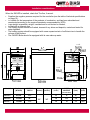
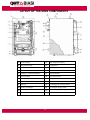
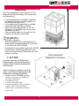
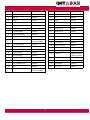
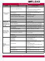
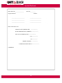
3Wood Cast Iron Boiler
SAVE THESE INSTRUCTIONS
For wood and
soft coal only.
IMPORTANT:
PLEASE READ THESE INSTRUCTIONS
CAREFULLY BEFORE PROCEEDING WITH
THE INSTALLATION OF THE BOILER.
THESE INSTRUCTIONS MUST BE POSTED
NEAR THE BOILER AND MAINTAINED IN
LEGIBLE CONDITION FOR REFERENCE
BY THE OWNER OR SERVICE PERSON.
Must be installed by
a qualified licensed
Heating Contractor.
OWNER:
For service and repairs to the
heating system, please contact your
Heating Contractor. The following
information should be filled in by
your Heating Contractor, and used
by you when seeking information
concerning the boiler.
Boiler Serial No._____________
Address:_________________________
Model No.___________
_________________________
Telephone Number:
_________________________
Heating Contractor:____________________
Rev. B 9/15/10
Dear Customer,
Thank you for buying a BIASI 3Wood Boiler.
The 3Wood Boiler system is a cast iron, solid fuel, hot water boiler, using
the famous Biasi (3-pass) design. This Boiler is rugged and engineered for
maximum heating efficiency.
We realize that it is not possible to answer all the questions about the
3Wood Boiler System in this manual. Reading this installation Manual does not
make the reader an expert in all aspects of installation and operation, and does
not replace the need for a qualified, licensed heating contractor. We urge you to
contact your installing contractor or distributor if you are in question about any
aspect of your boilers performance. Our main concern is that you are satisfied
with your boiler and its performance.
All BIASI boiler blocks are built in accordance with ASME boiler
pressure vessel code, and bear the “H” stamp. The entire range of 3Wood
Boilers have been tested to ETL standards.
The BIASI 3Wood boiler block has a limited lifetime warranty (refer to
back of manual).
Thank you for purchasing our 3Wood series boiler. If you have any
questions or comments call please don’t hesitate to contact us immediately .
Our goal is 100% customer satisfaction.
Sincerely,
QHT Inc.
2
Table of Contents
Important Information
4
5-6
Warnings and safety rules, Identification
Procedure in event of power failure
7
Refueling the Boiler
8
Wood Burning
9
Heat value of wood, Wood Storage, Ash Removal
10
Creosote, Runaway Fire
11
Chimneys
12
Coal Firing
13
3Wood Design
14
Installation Considerations
15
Layout of Main Components
16
Transporting and Minimum Clearances
17
Flue Gas Outlet and Combustion Air
18
Assembling the Casing
19
Installation of Controls
20
Installations of Flue Gas Partition and Draft Regulator
21,22
23
Commissioning the Boiler
3WOOD as only boiler piping and wiring
24,25
4 Way Mixing Valve Piping and Wiring
26,27,28
Parallel Piping and Wiring
29,30,31
Boiler and Casing Parts
32,33,34
Useful References
35
Shutdown
36
Troubleshooting
37
System Checkout
38
Warranty
39
3
IMPORTANT INFORMATION
Please read this page carefully.
ALL BOILERS MUST BE INSTALLED IN ACCORDANCE WITH NATIONAL, STATE AND LOCAL PLUMBING,
HEATING AND ELECTRICAL CODES AND ORDINANCES, AS WELL AS THE REGULATIONS OF THE SERVING
ELECTRICAL, WATER AND GAS UTILITIES.
All systems should be designed and installed by licensed heating contractors who are knowledgeable in the layout and
installation of multi-fuel heating systems.
WARNING
·
·
·
·
·
·
·
·
·
·
·
The 3WOOD Boiler must be positioned to provide at least 36” of clearance between any combustible material and the
sides, rear, and top of the boiler. At least 60” must be provided between the front of the boiler and any combustible
material. Boiler must be set on a non-combustible floor.
Do not burn volatile garbage, gasoline, naphtha, propane, engine oil, or other flammable liquids. All flammable liquids
(especially gasoline), debris, rags, paper, wood scraps, etc., should be kept clear of the boiler at all times. Keep the
boiler area clean and free of fire hazards.
All 3WOOD Boilers must be connected to a tile-lined flue with a minimum size of 8”x 8” or to an insulated metal chimney
with a minimum size of 6”. NO OTHER APPLIANCE SHOULD BE VENTED THROUGH THIS FLUE! Your chimney flue
should be inspected regularly (BI-Monthly) for any build up of fly ash or creosote.
It is the responsibility of the installing contractor to see that all controls are correctly installed and are operating properly
when the installation is completed.
Please read the literature and warranty supplied by the manufacturer of the various accessory devices.
These devices are warranted by the manufacturer, not by QHT, Inc. or BIASI. These accessory devices must be
installed and used according to the recommendations of the manufacturer.
Do not use self contained, non-electrical zone valves in the zone controlled by the overheat control.
When references are made to tapping numbers, please refer to the specifications sections.
All firewood used in this boiler must be dried to moisture content of 20% or less. (see pg.11)
Homeowners should read and familiarize themselves with “Procedure In Event Of Power Failure”. (see pg.9)
Anyone who is going to operate this boiler MUST read and familiarize himself or herself with “Starting And Maintaining A
Fire”. (see pg.23)
DANGER
COAL FIRES CAN PRODUCE POISONOUS GASES!
All coal fires produce large quantities of carbon monoxide (CO), a highly poisonous gas. Exposure to this gas produces
drowsiness, sleep and, in some cases, brain damage or even death. Since carbon monoxide is odorless and colorless, the
victim is rarely aware that he or she is being overcome until it is too late.
Normally, carbon monoxide burns as a blue flame over the coal bed, but under and of the following conditions, unburnt
carbon monoxide gas could escape from the combustion chamber, stove pipe, flue or chimney and enter the house:
· A blocked chimney
· An internal blockage in the heating appliance that can be caused by a build up of ashes, poor positioning of the coal,
or firing with too much fuel.
· A closed smoke pipe damper
· A poor chimney draft
If you are burning coal or plan to burn coal, make certain that none of the conditions listed above exist. If you have any
questions about coal burning, please consult with your contractor or the BIASI Distributor.
Codes and Regulations
Installation of the boiler, and related equipment must conform to national, state and local regulations codes applicable to
the installation of the equipment. In the absence of local requirements, the following codes apply:
National Fire Protection Association (NFPA)
CSA International
Battery March Park
8501 East Pleasant Valley Road
Quincy, MA 02269
Cleveland, OH 44134
http://www.nfpa.org
www.csa-international.org
4
WARNING
·
·
·
·
·
·
SAFETY RULES
After removing the packaging, check that the material supplied is intact and complete; if this is not the case, contact
the heating contractor that sold the 3WOOD Boiler.
The 3WOOD Boiler must be installed by a licensed heating contractor in compliance with the National, State and
Local codes in force and the instructions provided in the manual supplied with the 3WOOD.
The 3WOOD Boiler must be used for the intended purpose. QHT BIASI is not liable for any injury or damages
caused to people, animals or things due to errors in installation, operation, maintenance and improper use of the
boiler.
In the event of water leaks, close the water supply and call your Heating Contractor.
The manual is an integral part of the 3WOOD and consequently must ALWAYS be kept with the 3WOOD
Boiler when transferred to another owner or user, or installed in another system. The manual must be kept carefully
and if damaged or lost a replacement can be ordered by calling QHT Biasi.(1-800-501-7697)
The 3WOOD Boiler is not to be used with an automatic stoker unless so certified.
·
The 3WOOD Boiler must be serviced at least once a year.
Caution: Hot surfaces; keep children away. Do not touch during operation.
·
·
DO NOT allow the boiler to be controlled by children or incapable persons without supervision.
DO NOT use chemicals or fluids to start the fire.
·
DO NOT burn garbage, gasoline, naphtha, propane, engine oil, or other flammable materials.
·
DO NOT fire the 3WOOD during a power failure. Use a wood stove during a power failure not a wood boiler.
·
DO NOT dispose of ashes in anything other then a steel container and do not store it in house.
·
DO NOT let the chimney draft exceed .2 inches of water column
·
DO NOT adjust or tamper with the chain which connects the Samson draft regulator to the air damper
·
DO NOT perform any cleaning operations when the boiler is hot or when there are coals inside the boiler.
·
DO NOT adjust the safety or control devices without consulting with the instructions of the manufacturer of the boiler.
·
DO NOT plug or reduce the size of the ventilation openings in the room where the boiler is installed and on the boiler
·
WARNING – RISK OF FIRE.
(if present). The ventilation openings are essential for correct combustion.
·
DO NOT leave containers with flammable substances in the boiler room where the boiler is installed.
·
DO NOT operate with fuel loading or ash doors open.
·
DO NOT store fuel or other combustible materials within marked installation clearances.
·
DO NOT overload the combustion chamber.
NOTE: Inspect and clean chimney flue regularly.
DANGER
DO NOT connect to any chimney or vent serving another appliance.
NOTE: For Canadian Installations, the boiler must be installed as per the following
Requirements:
·
CAN/CSA-B365 Changes to the installation must comply with CAN/CGA-B149.1
·
Can/CGA-B149.2 (for gas fired), C22.1 (for electric), CSA B139 (for oil fired)
5
WARNING
·
·
·
-Canadian
Operate the (gas, Oil, Electric) boiler periodically to ensure that it will operate satisfactory when needed.
DO NOT relocate or by-pass any of the safety controls in the original boiler installation.
The operation of the gas boiler must be verified for acceptance operation before and after installation of the
add-on boiler by a gas filter who is recognized by a regulatory body.
Note: Only wood and bituminous coal can be burned in this boiler.
IDENTIFICATION
The 3WOOD Boiler is identified by:
·
The ETL Name Plate that MUST be applied by QHT Inc, so that it is legible when the 3WOOD is installed
(for example, on the top panel as shown on page 20).
·
The ASME Plate is fastened to the front of the boiler on the casting.
Before Installing
WHEN SERVICING BOILER
· To avoid electric shock, disconnect electrical supply before performing maintenance.
· To avoid severe burns, allow boiler to cool before performing maintenance.
BOILER OPERATION
· Do not block flow of combustion or ventilation air to boiler.
· Should overheating occur do not disconnect electrical supply to circulator. Instead, open all the flow checks external
to the Boilers.
· Do not use this boiler if any part has been under water. Immediately call a qualified service technician to inspect the
boiler and to replace any part of the control system.
· Do not overload the boiler.
BOILER WATER
· If you have an old system with cast iron radiators, thoroughly flush the system (without boiler connected) to remove
sediment.
· Do not use petroleum-based cleaning or sealing compounds in boiler system.
· Use only inhibits propylene glycol which are specifically formulated for hydronic systems.
· Continual fresh make-up water will reduce boiler life. Mineral buildup in heat exchanger reduces heat transfer,
overheats the stainless steel heat exchanger, and causes failure. Addition of oxygen carried in by make-up water can
cause internal corrosion in system components. Leaks in boiler or piping must be repaired at once to prevent makeup water.
6
PROCEDURE IN EVENT OF POWER FAILURE
Should your electricity go off during the heating season, there are several procedures that should be
followed in order that you may continue to safely operate your heating system. These procedures apply to the
solid-fuel boiler, as the gas or oil-fired boiler, if any, will be completely inoperative.
1. Locate any “flow-check” valves in the system (See Pg. 7), and completely unscrew the knob on the top of
all these valves. (This will allow a certain amount of heated water to circulate by convection throughout the
house, preventing the pipes from freezing and keeping the house partially heated).
Note: This does not apply to gravity systems, as they have no flow-check
valves, and will continue to operate normally without electricity.
2. The automatic draft regulator will continue to control the wood fire in the absence of electric power. It is
important to remember that the heating system cannot dispose of a great deal of fuel without a circulator
running.
Exploded view of top bushing arrangement
1.
2.
Remove factory bushing and replace with provided steel adapter
(1)
Place OverHeat aquastat in a tee
(not provided) above the steel
adapter (provided) into the short
3/4 immersion well. (provided)
PIPING NOTES:
1. This drawing is meant to show system piping
concept only. The installer is responsible for all
equipment & detailing required by local codes.
2. Discharge of Pressure Relief Valve must be piped
without valves to within 3” of the floor.
3. Where required, Low Water Cutoff must be
installed in the Supply piping of the oil/gas boiler
7
REFUELING THE BOILER
CAUTION
·
·
·
·
Use extreme caution when refueling the boiler. If the door is opened too quickly, the unburned hot gases
may ignite and cause a back puff. This is especially true with very dry wood.
DO NOT tamper with the chain on the draft regulator as it could cause the fire to burn out of control.
Keep ash and fuel doors closed if not refueling boiler.
DO NOT overload the boiler.
Adjusting the Flue Gas Damper
To Re-fire the boiler, open the flue gas damper to establish more draft through the combustion chamber. After refueling, when the fire is established, it probably will be necessary to close the flue gas damper to match
the heating requirements and accommodate the chimney draft.
Reloading Wood
CAUTION
To reload wood in the firebox, Carefully open the top fire door an inch or so until you can see that the fire is
burning well and the smoke is exhausting up into the heat exchanger above the firebox. While loading, the door can
be left fully open and logs can be added by swinging the flue gas damper open. Logs should be 1” or 2” shorter than
the firebox in the boiler and should be of such diameter as not to “bridge” or jam in the firebox. Logs of 2” to 4” in
diameter should be used whenever possible. This will produce an even burning and efficient fire. Wood split to this
size also dries much more quickly. The logs should be stacked and lined up horizontally so the burning wood can
settle easily. Add the largest wood when the fire is burning well and some coals are forming. After you have filled
the firebox to the desired level, close the loading door securely. Damage or injury will result if wood is not loaded
carefully generally level with bottom of flue gas damper. If loaded in-correctly there is a risk of fire or injury.
In long- term maintenance of the boiler fire, frequent stoking with small amounts of wood is better than infrequent stoking with larger amounts. When you stoke the fire, pull some of the hot coals forward in the firebox
where they can get sufficient air to burn thereby enabling them to set fire to the next load of wood.
Draft Regulator
The draft regulator should be adjusted as follows:
It may take several trials adjusting the Samson control setting to maintain the proper boiler temperature during
wood firing of approximately 180-190°F. The final control setting may be a little more or a little less then the red
80°C on the dial. During normal operation, especially in the spring or fall, it is necessary to allow air to enter
through the secondary air damper. This method reduces the possibility of creosote formation when the lower air flap
is fully closed.
1. Turn the black knob counterclockwise to set the red number from 40°C to 80°C at the red line.
2. Allow the wood fire to slowly bring the boiler temperature up to about 180°F on the temperature gauge.
3. As this temperature is reached, the lower door air inlet flap will begin to close because the proper combustion of
air has entered the firebox to maintain the selected boiler temperature.
DO NOT tamper with the chain on the draft regulator as it could cause the fire to burn out of control.
CAUTION
Empty the ashes before they touch the grates so they will not interfere with the airflow to the vertical flue
passages
8
WOOD BURNING
Overview
Burn dry and well-seasoned hardwood with a moisture content of 20% or less. Wood must
be seasoned at least six months; however, it is preferable to season it for a year to eighteen
months. Seasoned wood will not only reduce creosote but will also produce more heat. Some seasoned hardwoods will yield 20-25% more heat. Wood-burners who ignore this advice are likely to
have dirty chimneys and inadequate performance from their boilers.
Theoretically, there are about 8,600 BTU available as heat from each pound of wood. It
takes about 1,000 BTU to evaporate each pound of moisture from a log. The wetter the wood, the
more energy it takes to get the moisture out of the firewood resulting in less energy to heat your
home. In addition, green wood usually burns at a low temperature, robbing you of even more heat
in the form of unburned chemicals and gases that it sends up the chimney. The moral is: do not
burn green wood.
Selecting Your Wood
If you buy green wood, season it before using. With some experience, you can spot green
wood easily. It is heavier and it looks different. Seasoned wood will often show cracks radiating
outward from the heartwood toward the bark, like wheel spokes. Green wood will not show this
pattern of cracks.
You get roughly the same amount of heat from a pound of equivalently dry wood no matter
what species of tree it comes from. But wood is not sold by the pound; it is sold by the cord i.e. by
volume. Therefore, the dense heavy woods are the ones to buy, the ones that give you more
pounds per cord. A cord of wood measures 4 feet x 4 feet x 8 feet. A cord of 4-foot logs thus
stacked occupies 128 cubic feet and contains about 80 cubic feet of solid wood, with the rest being air space between the logs. If you buy a cord of wood, cut it to length and split it, you will find
it does not occupy 128 cubic feet when stacked. You have not necessarily been cheated. A cord cut
to length and split packs more tightly thereby occupying less space. Often the best time to buy
wood is in late winter or early spring. Green wood can sometimes be purchased at low prices in
spring or early summer.
Cutting and Drying Your Own Wood
A good time to cut your own wood is in the late winter or early spring, as soon as the woods
are free of snow. Then hold the wood for use in 18 months. If you cut trees in the spring or summer, let them lie a while until the leaves wither. The leaves will draw moisture from the wood;
drying it more quickly than if you limbed the tree immediately.
If you want your wood to dry as quickly as possible, cut it to length and split it. Stack it
where the air can move through the pile and shelter it from the weather. A wood shed with air
vents in the sidewalls, like a tobacco-drying barn, is effective.
9
The Heat Value of Wood
The following chart compiled by the United States Forest Products Laboratory indicates the
amount of heat available per cord of wood from a few representative tree species. Other good to
very good species would include apple, walnut, pecan, dogwood, cypress, sycamore and gum. The
latter two are hard to split, as is elm.
Available Heat Per Cord
In Millions of BTU/ HR
Green Wood
Air-Dry
Percent More Heat For Air-Dry Wood
Ash
16.5
20.0
21
Aspen (Popple, Poplar)
10.3
12.5
25
Beech, American
17.3
21.8
26
Birch, Yellow
17.3
21.3
23
Douglas Fir, Heartwood
13.0
18.0
38
Elm. American
14.3
17.2
20
Hickory, Shagbark
20.7
24.8
19
Maple, Red
15.0
18.8
24
Maple, Sugar
18.4
21.3
16
Oak, Red
17.9
21.3
19
Oak, White
19.2
22.7
18
Pine, Easter White
13.1
13.3
10
Pine, Southern yellow
14.2
20.5
44
Species
WOOD STORAGE
Store your wood outside of the minimum clearances recommended on the drawings on page 19.
Generally wood should be stored in the basement or barn, garage where insects wont bother the house. If fans
are installed within fuel storage area, they should not create negative pressure in the room where the 3WOOD
is located.
CAUTION
ASH REMOVAL
Before refueling the boiler, check the ash pan under grates and remove and dump ashes if full into a
metal container. Replace the ash pan and close the ash door. After re-fueling, take the ash container and leave
it outside the house.
10
CREOSOTE
Creosote condenses from the flue gases more quickly when the temperature in the chimney is
low. The actual amount of creosote deposited is dependent on:
1. The amount of moisture in the flue gases.
2. The temperature of the stack,
3. The rate at which the wood is burned.
4. The amount of draft in the stack.
5. How completely the combustible elements in the flue gases have been burned in the combustion
chamber. Most problems with creosote are due to insufficiently dry wood, poor chimney with low draft
and cold walls, and/or a low rate of burning when little heat is required during the spring and fall
months.
Moisture in the flue gases may be controlled by:
· Using properly seasoned firewood.
· Mixing small pieces (preferably slab wood) with every full load.
· Never use only large wood (usually less dry) during mild weather when combustion is relatively slow.
The temperature in the stack may be controlled by:
· Using as short a length of stovepipe with as few elbows as possible between the boiler and the
chimney.
The amount of draft in the stack may be controlled by:
· Insuring adequate chimney height and preventing air leaks in places such as around the ash pit door.
· Eliminating external obstructions in the chimney outlet.
· Insulating chimney from heat loss.
CAUTION
Procedure in the event of a runaway fire or chimney fire
If the Boiler-Fire is out of control (or creosote in chimney has caught fire) Do
the Following:
· Close flue gas damper
· Turn knob on draft regulator to 40°C
· Turn-up thermostats in house
· DO NOT dose the fire with water as injury from steam could occur
11
Chimneys
WARNING
Do NOT connect this unit to a chimney flue serving another appliance.
Downdrafts
Downdrafts can result from improper chimney height, nearby buildings, tree that are taller then the chimney,
and too large of a flue. To help minimize this problem, the top of the chimney must be at least three feet above the
point at which it passes through the roof and two feet above the highest point of the roof. In addition, the chimney
should be at least as high or higher than the tallest section of any adjacent roof.
WARNING
Chimney Construction
Fire insurance underwriters favor and sometimes require masonry construction for chimneys because tilelined masonry chimneys are strong and not likely to crack from high temperatures.
Insulating your chimney flue liner will create a consistent natural draft by keeping the temperature of the flue
gasses higher then the atmospheric temperature around the chimney. Insulation will also reduce creosote deposits by
reducing the moisture condensation from the flue gases.
· 3WOOD must be connected to its own separate flue. It must NOT be installed in a flue which is connected to
another appliance.
· The recommended low heat, tile lined, masonry chimney should have a minimum 8”x 8” flue and be at least 18
feet tall.
· A H.T. metal chimney is recommended and should have a stainless steel liner 7”ø.
· The exhaust pipe should be minimum 24 gauge and 7”ø black or blued steel. It is suggested to point the
male end of the pipe downward to prevent leaking creosote.
Chimney Cleaning
Check your chimney and flue pipe at least twice during the heating season. check it more frequently if you
are new to wood or believe that there is soot or creosote build up.
A small amount of smoke can infiltrate the room when you refuel the boiler.
However, if this happens increasingly you may have a chimney blockage. To find out the cause, look into the
chimney from above or below. If neither option is convenient, then use a mirror and a flashlight to look up the flue
utilizing the clean out door as an access point.
To clean your chimney, you can contact a professional chimney sweep or use several do-it-yourself cleaning
methods. The most efficient device for scrubbing your chimney flue is a wire chimney brush that is designed for
cleaning solid fuel flues. These brushes are available in standard sizes for both rectangular and round flues. Another
option is to fill a burlap bag with straw or rolled up chicken wire, tie it to a rope and drop the rope down to a helper.
You can then pull the bag up and down in the chimney to scrub away and buildup. Similar methods include using a
bunch of tire chains tied to a rope or tying a burlap sack to the end of a long pole, provided your chimney is not to
tall.
Chemical chimney cleaners such as “chimney sweep” are available. These products are added to the hot fire
in order to break down the creosote. We do not know how their long term effects on a chimney or boiler, but we
have been advised that any chemical salt added to the fire may cause corrosion in insulated metal chimneys, boilers,
and stovepipes. In addition, these products can be harmful to your health.
12
COAL FIRE
DANGER
COAL FIRES CAN PRODUCE POISONOUS GASES!
All coal fires produce large quantities of carbon monoxide (CO) a highly poisonous gas. Exposure to this gas produces
drowsiness, sleep, and in some cases, brain damage or even death. Since carbon monoxide is odorless and colorless, the victim is
rarely aware that he or she is being overcome until it is too late.
Normally, carbon monoxide burns as a blue flame over the coal bed, but under any of the following conditions, unburnt
carbon monoxide gas could escape from the combustion chamber, stove pipe, flue or chimney and enter the house:
· A blocked chimney
· An internal blockage in the heating appliance that can be caused by a building up of ashes, poor positioning of the fuel, or firing
with too much fuel.
· A closed smoke pipe damper
· A poor chimney draft.
If you are burning coal or plan to burn coal, make certain that none of the conditions listed above exist. If you have any questions
about coal burning, starting or maintaining a coal fire please consult with your contractor.
CAUTION
BURN BITUMINOUS (SOFT) COAL ONLY
Your success with coal burning will improve with experience, as it takes time to familiarize yourself with your new boiler and various
fuels. Getting the maximum heat out of your coal generally depends on these factors:
· Proper firing technique with adequate draft.
· Clean heat exchanger surfaces in you boilers.
· Quality Bituminous (soft) coal of the proper size.(1-1/2” -2-1/2” diameter coal).
It is best to build a coal fire by gradually adding coal over a well established bed of wood coals. Before adding fuel, check to see that
the ashes are removed from the lower door and that there is clear draft up through the grate area.
The type, quality and size of the coal you are using will affect the kindling rate and time required to establish a good, deep coal bed.
There are no set rules, but the following suggestions may help:
1. Don’t run too low a fire. Once you have a good hot coal bed, keep the firebox full to the level of the fire door. Bank the coal bed
sloping down to the sides and the front below the bottom of loading door. A good deep fire is more economical than a low, thin
one. DO NOT overload the combustion chamber.
2. Be sure to leave a “hot spot” (an area of exposed, glowing coals) to ignite the gases released from the fresh coal.
3. Be sure to clean out ashes from below grates before adding fuel. Be sure to remove and store ashes only in a metal container,
preferably with a cover like a trash can, some people even sift ashes to remove large unburned chunks of coal to be reburned.
Glowing embers in a bed of ashes can remain hot for many days– so be very careful of how you dispose of ash from both wood
and coal fires!
4. Don’t allow coal dust and soot to accumulate on the inside surfaces of your boiler. Coal dust has an even higher insulating value
than creosote, so it is a good habit to brush away any accumulation daily. Be careful to check the cleanout in the rear smoke
hood at least once a week.
5. Don’t disturb the fire once you have a good coal bed.
6. If you have trouble starting or maintaining a fire, you may want to mix fuels. Generally, softer coals kindle and burn better in
smaller fireboxes and start up better. Coal over wood coals and gradually establish a good coal fire with bituminous “chestnut”,
“stove”, or “egg” coal. You can also freely mix various wood types. A good way to clean any creosote buildup from a regular wood
fire is to occasionally burn 100-200 pounds of coal.)
SPECIAL PRECAUTIONS MUST BE TAKEN WHEN BURNING COAL TO AVOID DANGER DUE TO CARBON MONOXIDE GAS
POISONING.
13
The 3WOOD Design
The 3WOOD Boilers are hot water generators that operate by combustion of hard wood or soft coal.
They feature a high quality and extremely thick ASME class 20 cast-iron body, protected by high-density
insulation that limits heat loss.
The large heat exchange surface and the fins in the flue gas path ensure exceptional resistance to
corrosion and very high efficiency that remains constant over time (self-cleaning effect).
The combustion chamber and the upper door for loading the wood are sufficiently large to maximize the
burn time and limit the number of times the door needs to be opened for refueling.
The front air grille for secondary air in the upper door and the flue gas damper are easily adjusted for
tending the fire.
Secondary combustion chamber
Technology with 3 Pass:
1st Pass
The combustion chamber gasses are carried by a special passage in the rear element. In the same area,
very hot secondary air is combined with combustion gases which enhance their oxidation.
2nd Pass
The gases from the rear element are reburned in the secondary combustion chamber,
3rd Pass
The third Pass consists of a wide-finned, self-cleaning zone which directs the smoke towards the flue
attachment with adjustment shutter and door cleaning.
14
Installation considerations
When the 3WOOD is installed, check that The flue, if reused:
·
·
·
·
·
·
·
Supplies the negative pressure required for the new boiler (see the table of technical specifications
on page 10);
is suitable for the temperature of the products of combustion, and has been calculated and
constructed according to the required standards; recommended by NFPA
is as straight as possible, airtight, insulated and is not blocked or choked;
is fitted with a cleanout door
The heating system should be flushed, cleaned of any slime and deposits, vented and tested for
water tightness.
The heating system should be equipped with a new expansion tank of sufficient size to handle the
volume of both boilers.
The 3WOOD Boiler should be equipped with its own make-up water.
1 1/2”
1 1/2”
Model #
Min. Output
(BTU/HR)
FIREBOX
DEPTH
Width
(inches)
Height
(inches)
Length
(inches)
WATER
CONTENT
Draft
(inch)
Weight
(LBS)
(US-GALLONS)
3Wood 5
89,000
16.5”
3Wood 6
104,000
20”
3Wood 7
120,000
23.5”
24”
38”
15
25
11
.07
695
30
12.5
.10
804
34
14
.12
903
LAYOUT OF THE MAIN COMPONENTS
1.
Pressure Gauge
13.
Flame Inspection Window
2.
Temperature Gauge
14.
Loading Door
3.
Flue Gas Chamber
15.
Draft Regulator
4.
Mobile Smoke Plate
16.
Flue Attachment
5.
Loading / Combustion Chamber
17.
Flue Gas Damper
6.
Flue Gas Baffle
18.
Flue Cleanout Door
7.
Ash Collection Chamber
19.
Casing
8.
Ash Pit Door
20.
Insulation
9.
Ash Tray
21.
1 1/2” Flange for Overheat control
10. Primary Air Damper
22.
1 1/2” Nipple (Supply Outlet)
11. Secondary Combustion Cover
23.
1 1/2” Bushing (Operating Control)
12. Secondary Air Regulator
24.
1 1/2” Flange (Return Outlet)
16
Transporting
Once the packaging has been removed, cut the
straps and remove the casing in such a way as to
avoid damaging it.
·
·
·
·
If hoisting equipment is available, suitable for
the weight of the boiler, use the eyebolts (1)
provided on the body to lift it
If no suitable hoisting equipment is available,
handle the boiler manually, as follows:
Remove the fastening screws (2) for the
baseboard (3) and take it off, so as to allow
the pallet to be tilted
Insert a suitably sized bar through the two
eyebolts (4) and lift the boiler body.
WARNING
·
·
·
Use safety equipment.
Must be Installed on non combustible floor or
cinder blocks extending at least 16" in front and
8" on either side of the 3 WOOD.
Construction of cement block pad under 3WOOD
should extend at least 8” to each side of the
boiler and extend at least 2” on either side of the
chimney connector
Recommended
Minimum Clearances
CAUTION
The room where the 3WOOD Boiler is
installed must be heated and must always
comply with the technical standards and
the local codes.
Allow for the space required to access the
safety / control devices and to perform the
maintenance and loading operations.
· Do Not install the 3WOOD appliances:
· Outdoors, as they are not designed for
this type of installation.
· In an unheated room.
· In rooms with exhaust fans.
· In houses with heat recovery ventilation
systems. (HRV) with out having a
outside source of ventilation air for the
boiler room.
17
WARNING
FLUE GAS OUTLET
The chimney and flue must be made in compliance with building codes and resistant to
high temperature, condensate and mechanical stress, and that are airtight.
·
Do not connect to any chimney flue or vent servicing another appliance.
·
The 3WOOD takes in the combustion air from the room where the boiler is installed, which
MUST FEATURE ventilation openings as required by NFPA standards.
The flue (1) must ensure the minimum negative draft between .07 and .12 as specified in the
draft section specified on page 17.
Undersized or incorrectly sized flues (1) and exhaust pipes (2) will cause problems of
condensation, which will affect combustion and plug the flue.
The joints should be installed with male ends facing down and sealed using materials that can
resist temperatures of at least 700°F.
·
·
·
WARNING
Note: Material of the chimney connector
(minimum 24 gauge black or blued steel)
NO GALVANIZED PIPE.
7”
COMBUSTION AIR INTAKE
A separate source of combustion air may be necessary if:
1. The solid-fuel-fired boiler does not draw steadily, smells,
experiences smoke roll-out or burns poorly.
2. Any of the above symptoms are alleviated by opening a
window slightly on a calm day.
SOURCES OF COMBUSTION AIR ARE:
·
·
A mechanical “Fan in a Can”.
A natural make-up air duct system with heat trap.
18
3. The house or basement is equipped with a wellsealed vapor barrier insulation envelope tight
fitting windows and/or has any powered devices
that exhaust house air.
4. There is excessive condensation on windows in
the winter.
5. A ventilation system is installed in the house.
ASSEMBLING THE CASING
A. Remove the outlet and return stubs from the cardboard box inside
the loading/combustion chamber, and install them
B. Fit a screw and nut in the holes on the four bottom brackets (1),
without tightening them
C. Insert them in the top of the four slots provided at the bottom of
the boiler, and secure them with the nuts.
NOTE:
The four top brackets (2) have holes for fastening the paneling to the
tie-rods
D. Fit a bolt and nut in the holes on the four bottom brackets (1),
without tightening them
E. Insert them in the four slots at the bottom of the boiler and tighten
them
F. Insert the four top brackets (2) on the studs and tighten them with
the nuts (3)
G. Apply the insulation (4) around the boiler body
H. Fit the side panels (5), hooking the slots (6) on the bottom of the
panels to the bottom brackets (1)
I. Fasten the panels (6) to the top brackets (2) using the
screws (7) supplied with the casing. Leave the right side loose
after removing the plug in the top of rear section
J.
K.
L.
M.
Fit the top rear panel (8), resting it on the side panels, and secure it with two screws (9)
Apply the rear insulation (10), inserting the edges in the openings at the side and top
Fit the rear panel (11) and fasten it with the six screws (12) supplied
Insert the top centre panel (13) underneath the top rear panel (8) and rest it on the side
panels
19
Installation of Controls
A. Insert the temperature gauge (16) in the housing on the front panel (15) and secure it
B. Partially unwind the capillary tube from the thermometer, insert the sensor in the probe socket (17)
and secure it with the fastening spring
C. Fit the front panel (15), handling the temperature gauge capillary tube to make sure it is not
damaged, and inserting the regulator in the opening provided
D. Secure it to the side panels using the screws supplied.
E. Insert pressure gauge (13) and capillary tube through the panel (15) and install probe into the
tapping on the upper right side of rear section of the boiler (17).
F. Tighten the draft regulator (14) in the housing provided on the boiler body. The cam w/bolt of the
regulator must be in the bottom position.
17
20
Installation of Flue Gas Partition
A. Open the loading door (1)
B. Remove the flue gas cover (2) by
turning the latch (3)
C. Insert the flue gas partition (4) in the
guide provided and press it fully into
the rear of the boiler.
D. Replace the cover (2) and secure
it with the latch (3)
E. Open the door on the ash collection
chamber (5) and insert the ash tray
(6)
Installation of Draft Regulator
A. The draft regulator is installed
horizontally. The hexagon screw (8)
must be facing bottom.
21
B. Hold the cam in position by hand,
remove the protector (9) and replace it
with the hexagonal handle (10) at a 45°
angle up from the center of the regulator.
C. Set the regulator knob (7) by turning
knob of regulator counter clockwise to
the white 30° mark which is the minimum
position (90°F).
D. Remove chain from bag and cut it 32”
long and install the hook and eyelet.
E. Secure the handle (10) by tightening
screw (11) Connect one end of the chain
to the hook and attach the hook to
handle (10).
F. Tighten the rod (12) into the threaded
hole on the door (must be level with
bottom of door) and secure it, using the
nut (14), in a horizontal position so the
end of rod is facing to the right
G. Attach the 2nd hook to the other end of
the chain and connect it to the end of the
rod (12). In this position the air door (13)
is fully
open.
CAUTION
NOTE:
Chain must be exactly 32 inches long.
IMPORTANT:
When assembly has been completed, the
Heating Contractor must make sure that the
ETL TECHNICAL RATING PLATE is attached
to the top panel of casing.
22
32”
Commissioning the 3WOOD Boiler:
WARNING
PRELIMINARY CHECKS/ Starting The Fire
Before starting a fire in the 3 WOOD, check that:
1. The 3WOOD is filled with water.
2. The valves are open in the distribution system.
3. The distribution system has been purged of all its air.
4. The exhaust pipe and combustion air controls and
dampers have been installed correctly.
5. The seals on flue and ash door are in good condition.
___________________________________________
STARTING AND MAINTAING A WOOD FIRE
A. Completely open the flue gas damper (1)
(horizontal position) on breaching.
B. Turn draft regulator knob clockwise to the red
mark 90°C
C. Move the secondary air regulator (3) to the
middle position
D. Adjust the primary air damper (4) so it is open
1/32” at the bottom (minimum opening) using
the screw (5). Lock it in place with the lock nut.
The regulator arm should be in a level position.
Note: Never detach the chain from the rods
or the handle.
E. Open the loading door (6), place small pieces
of paper and dry kindling wood on the top of
the grates and ignite them
F. Wait for kindling to ignite, complete the load
with larger pieces of wood not higher than
bottom of flap, then close the loading door (6)
G. Ensure the boiler has adequate combustion air
from vents to the boiler room. Air can be taken
from basement brought in from the outside.
23
1/32”
DO NOT OVERLOAD ABOVE FLAP
3WOOD boiler piping and wiring Considerations
Before choosing a particular system for your installation, the possibility of using a mixing valve
arrangement to avoid the problems of overheating should be considered. These systems will continuously
release heat to the distribution system in proportion to the outside temperature or other load factor. Such an
arrangement can be added to any heating system, and is one of the most sophisticated methods of heating
system regulation available. We strongly recommend a mixing system with all of our solid fuel systems.
A.
3WOOD AS THE ONLY BOILER
The 3WOOD boiler can be used as the only boiler in your heating system. Of course, the disadvantage
of the installation is that there will be no automatic back-up system for times when the solid fuel fire
will be unattended. For automatic switch-over from solid fuel to oil or gas, a tandem hookup of the
3WOOD with a second oil or gas boiler is recommended (see Section B). The obvious advantage of
this set-up is the cost saving involved in the elimination of the conventional boiler, controls and piping
required. It should be noted that the 3WOOD boiler is extremely efficient when fired with wood or
coal. Many people use the 3WOOD boiler in conjunction with direct vent gas or electric space heaters
located in the living spaces.
The following outlines a typical installation of a stand-alone 3WOOD boiler in a system planned for
solid fuel firing.
1. The supply tapping goes to the heating radiation. Install a “tee” with a 1” branch in the line to the
radiation, as close to the boiler as possible. This branch tee should point up and will route the
piping to the “dump zone”. There must not be a valve or any potential restriction between the
boiler and this tee.
2. in the boiler supply piping, install an air purger and expansion tank sized to handle the water in the
distribution system as well as the 3WOOD boiler.
3. Pipe the make-up water into the boiler through a Watts 1156F fill valve (pressure reducing valve)
into the lower rear ½” tapping at the bottom of the boiler.
4. Install a tee with a 1” branch for the dump zone in the return tapping. Point the branch of the tee
up.
5. The circulator should be installed in the return line from the heating radiation. The return is piped
into the boiler through the running end of the tee.
6. A circulator relay, Honeywell R845 or equivalent may control the circulator. Both the room
thermostat and the Overheat Aquastat installed in the 3WOOD boiler control this relay.
NOTE: In a case where the thermostat is calling for heat and boiler fire is out or otherwise unable to meet the
heating demands of the house, the circulator will continue to run. This has the advantage of helping
prevent the water in the system from freezing if the house temperature drops below 32F. If the
circulator is deactivated, the system must be drained if subfreezing interior temperatures are
anticipated! As an alternative to draining the system, a mixture of heating system, anti-freeze
(propylene glycol) and water can be used in place of normal water in the system. Such a mixture
should only be added after the system is thoroughly checked for leaks.
24
Note: Power failure
reference page 9.
Thermostat
NOTE: All wiring must be done in accordance with applicable state, local and national codes. Use only copper conductors.
3Wood installed in combination with a oil/gas boiler
Note: The operation of the gas boiler must be verified for acceptable operation before and after
installation of the add-on appliance by a gas fitter who is recognized by the regulatory
authority.
CAUTION
PIPING NOTES:
1. This drawing is meant to show system piping concept only.
2. The installer is responsible for all equipment & detailing required by local codes.
3. Discharge of Pressure Relief Valve must be piped without valves to within 3” of the floor.
4. Where required, Low Water Cutoff must be installed in the Supply piping of the oil/gas boiler.
5. DO NOT interfere with the normal delivery of heated water from the original boiler to the system.
6. Make sure that excessive pressure will not be developed in any portion of the boiler or system through
properly sizing the expansion tank.
25
B.
4-WAY MIXING VALVE Installed with 3WOOD Boiler in Combination with Oil/Gas Boiler
1. A mixing valve arrangement is a method of controlling house temperature that is different than traditional American
systems. In the average hydronic system, circulating or not circulating water of a fairly high and relatively constant
temperature to radiation controls temperature in the house or zone. The thermostat used in such a system is a simple
switch to a relay, which turns the circulator on and off. In a mixing valve controlled system, the circulator runs
continuously, and the temperature of the water flowing to the house is varied by the mixing valve, which adds more or
less cooler return water to the boiler-heated, water being pumped to the radiation. The valve is controlled manually by
the homeowner (a very common system in Europe), or is controlled automatically by an outdoor reset control.
A system controlled by a mixing valve has several advantages over a conventional off/on system.
· Fuel savings of 20%
· Longer boiler life due to elimination of thermal shock to the boiler caused by surges of cold return water at
circulator start-up
· A quieter and more comfortable house, because heat is more even. Rather than having the heat turn
completely on and completely off in response to heating demands, causing fluctuation in the house
temperature, the heat is always “on” with the temperature of the radiation adjusting gradually to respond to
the house’s needs.
In addition, a mixing valve arrangement has very important advantages for solid fuel burning hot water systems.
Because there is constant circulation, there is always some heat being drawn from the boiler. Since a solid fuel is
always generating a certain amount of heat, such a system will dispose of this heat efficiently. In conventional
system, there is a grater possibility of the boiler overheating (when there is no circulation) and creosote formation
(caused by the fire burning too slowly). A mixing valve system minimizes the possibility of either of those
problems occurring, thus increasing both the safety and efficiency of the solid fuel system.
Mixing valve arrangements can be added to any of the systems described in this section or, in fact, to any
conventional heating system as well. We recommend the 4-way mixing valve to control the temperature of the
heating radiation. To mix wood heated boiler water with the return water from the distribution system, the boiler
supply pipe must enter the mixing valve opposite the heating return pipe.
The following outlines a typical installation of a mixing valve controlled distribution system with a 3WOOD boiler in a system
planned for solid fuel firing with back-up from a oil or gas-fired boiler.
1.
2.
3.
4.
5.
6.
7.
The line from the 3WOOD boiler supply tapping goes to the oil/gas boiler supply pipe. Install a “tee” with a 1” branch in the
line as close to the 3WOOD boiler as possible. This branch tee should point up and will route the piping to the “dump zone”.
There must not be a valve or any potential restriction between the boiler and this tee.
Immediately after the “dump-zone” tee, install another tee with a ½ inch branch to install the L4006B aquastat to operate the
overheat override.
In the boiler supply piping install an air purger and expansion tank sized to handle the water in the distribution system as well
as the 3WOOD boiler.
Pipe the make-up water into the 3WOOD boiler and the oil/gas boiler through a Watts 1156F fill valve (pressure reducing
valve) into the lower rear ½” tapping at the bottom of the 3WOOD boiler and also into the oil/gas boiler.
Install a tee with a 1” branch for the dump zone in the return tapping as close to the 3WOOD boiler as possible. Point the
branch of the tee up.
The 3WOOD boiler circulator should be installed from the other pipe-leg of the tee to the return tapping of the gas/oil boiler.
The 3WOOD boiler circulator may be controlled by an outdoor reset controller operating the mixing valve, the oil/gas boiler
relay or a Honeywell R845 or equivalent if the mixing valve is manually operated. This relay is controlled by the 3WOOD
boiler Aquastat.
26
27
PIPING NOTES:
1. This drawing is meant to show system piping concept only.
The installer is responsible for all equipment & detailing required by local codes.
2. Discharge of Pressure Relief Valve must be piped without valves to within 3” of the floor.
3. Where required, Low Water Cutoff must be installed in the Supply piping of the oil/gas boiler
4. The 3Wood boiler must not interfere with the normal delivery of heated water from the original boiler.
5. The 3Wood boiler must have its own make-up water supply.
(Circulators, Controls, Valves & Wiring for 3 WOOD, Boiler supplied by others.)
4 Way Mixing Valve Piping
28
NOTE: All wiring must be done in accordance with applicable state, local and national codes. Use only copper conductors.
The 3WOOD must be installed without changing the function of the controls or rewiring the original boiler. A wiring interconnection
is permitted. The electrical system of both boilers shall be powered from a single branch circuit without exception.
C.
3WOOD Boiler with circulator Piped in Parallel with Oil/Gas Boiler
In the traditional American baseboard, hydronic system, the heating temperature in the house or zone is controlled by circulating
or not circulating water of a fairly high and relatively constant temperature to radiation. The thermostat used in such a system is a
simple switch to a relay which turns the circulator on and off. The vast majority of American heating systems use cast iron
boilers which have internal tankless coils for producing domestic hot water. The parallel piping arrangement is the correct
application for maintaining temperature in the oil/gas boiler with wood heated hot water as well as heating the radiation in the
house. Since the specifics of such a system will vary from installation to installation, the following procedure provides an
example of one specific installation which can be used as a model for actual situations.
1. Insure that the existing system has flow checks or electric zone valves in the supply lines to the various heating zones, and that the
Space heat and DHW circulators are mounted on the return line going back to the Oil/Gas boiler. If not, they must be installed in
these locations.
2. Remove the existing radiation supply and return lines from the oil or gas-fired boiler. Install pipe tees on the supply and returns
from nipples coming out of the existing oil/gas boiler. NOTE: Occasionally, extra supply and return taps are available on oil/gas
boilers. These plugs may be removed and used to run the lines between boilers. Re-install the supply and return lines.
3. Install a tee with a 1”branch coming out of the supply tapping of the 3WOOD boiler for the dump zone.
4. Then install another tee with a ¾” branch for the Aquastat for the 3WOOD boiler’s circulator. Install the Honeywell L4006B
into the branch of the tee using the 3/4 “ immersion well. Caution: Be careful to maintain a 12” minimum clearance between the
5.
flue pipe and the 3WOOD boiler aquastat.
Pipe from this tee to the supply pipe on the existing oil/gas boiler.
Note: By adding the gallonage from the addition of the 3WOOD boiler, an expansion tank should be added or the existing
tank should be increased in capacity.
6.
Install a tee with a 1” branch coming out of the return tapping of the 3WOOD boiler for the dump zone.
7.
Install piping, flow check and circulator from 3WOOD boiler to the return manifold installed on the oil/gas boiler.
Note: Aquastat settings for the existing oil/gas boiler should be as follows:
High Limit – 165F
Low Limit - 150F
Circulator - 140F
But these settings can be raised if the 3WOOD boiler isn’t fired for extended periods of time.
29
30
PIPING NOTES:
1. This drawing is meant to show system piping concept only.
The installer is responsible for all equipment & detailing required by local codes.
2. Discharge of Pressure Relief Valve must be piped without valves to within 3” of the floor.
3. Where required, Low Water Cutoff must be installed in the Supply piping of the oil/gas boiler
4. The 3Wood boiler must not interfere with the normal delivery of heated water from the original boiler.
5. The 3Wood boiler must have its own make-up water supply
(Circulators, Controls, Valves & Wiring for 3 WOOD, Boiler supplied by others.)
Parallel Piping
31
NOTE: All wiring must be done in accordance with applicable state, local and national codes. Use only copper conductors.
The 3WOOD must be installed without changing the function of the controls or rewiring the original boiler. A wiring interconnection
is permitted. The electrical system of both boilers shall be powered from a single branch circuit without exception.
32
#
Description
3WOOD 4,5,6,7
21
Bottom Door
59200644
1
Stud Screw
59200619
22
Hinge
59200645
2
Bushing
59200620
23
Pin
59200646
3
Flange
59200621
24
Gasket
59200729
4
Side Tapping
25
Flame Guard
59200647
5
Rear Boiler Section
59200623
26
Top Door
59200648
6
Intermediate Boiler Sections
59200624
27
Handle Catch
59200649
7
Top Push Nipples
59200625
28
Handle Catch
59200650
8
Bottom Push Nipples
59200626
29
Regulator
59200651
9
Bushing
59200627
30
Lower Door Stop
59200652
10
Tie Rod
59200628,59200629
59200630,59200631
31
Air Baffle
59200653
32
Flame Guard
59200654
11
Front Boiler Section
59200632
33
Upper Door Stop
59200655
12
Temperature Gauge
59200633
34
Load Door Grille
59200656
13
Bushing
59200634
35
Secondary Air Grille
59200657
14
Inspection Port
59200635
36
Ash Tray
15
Immersion Well
59200636
59200658,59200659,
59200660,59200661
16
Flue Gas Baffle
59200637
37
Flue Collar Clean-Out
59200662
17
Draft Regulator
59200638
38
Flue Collar Spacer
59200663
18
Flue Gas Baffle Lock
59200639
39
Flue Damper
59200664
19
Plate
59200640
40
Flue Collar
59200665
20
Partition
59200641,59200641
59200642,59200643
33
#
Description
3WOOD-4
3WOOD-5
3WOOD-6
3WOOD-7
1
Top Rear Panel
59200600
59200600
59200600
59200600
2
Insulation Assembly
59200601
59200602
59200603
59200604
3
Rear Panel
59200605
59200605
59200605
59200605
4
Cover Panel
59200606
59200607
59200608
59200609
5
Right Side Panel
59200610
59200611
59200612
59200613
6
Front Panel
59200614
59200614
59200614
59200614
7
Left Side Panel
59200615
59200616
59200617
59200618
34
35
SHUTDOWN
Extended Shutdown:
If the boiler is not used for an extended period, the following operations must be performed:
·
·
·
Close the on-off valves connected to the 3WOOD Boiler.
Remove the ash and clean the flue gas path.
Assess whether the Technical Service needs to be contacted for more through cleaning.
WARNING
·
·
Empty the system or add Non– Toxic antifreeze fluids to the heat system if there is danger of
frost.
A container with powdered lime should be placed inside the boiler to absorb humidity.
Maintenance:
Periodical maintenance is a legal requirement and is essential for the safety, efficiency and life of the
3WOOD Boiler.
It must be performed by a qualified heating contractor at least once a year so as to clean the entire flue
gas path : loading/combustion chamber, smoke box and flues.
Routine Cleaning:
Before starting any cleaning operations wait for the boiler to cool down.
External Cleaning:
The casing can be cleaned using cloths dipped in soap and water.
For hard-to-remove stains, dip the cloth in a mixture of 50% water and denatured alcohol or other
specific products. Once finished cleaning, carefully dry the 3WOOD Boiler.
WARNING
·
·
·
·
Do not use abrasive products, petrol or trichloroethylene.
Always make sure there are NO hot coals underneath the ash.
Use suitable safety equipment.
The boiler is supplied without accessories, as cleaning can be performed using
normal household utensils that can be purchased at shops that sell products for
stoves and fireplaces.
36
Troubleshooting
Problem
Cause
Corrective action
- Clean and check the tightness of the flue gas
path
- Fumes are escaping into the air
- Check that the loading and combustion
chamber doors close correctly
There is a smell
of fumes.
The boiler has
reached the set
temperature but
the radiators are
still cold.
The boiler does
not reach the set
temperature
- Check correct operation and replace if
- Draft Regulator
necessary
- Chain unhooked or broken
- Hook chain or replace it
- Primary air regulator damper jammed
- Release the damper
- Load wood
- Follow the procedure described in this manual
- Flue gas damper
- Check and adjust the position, if necessary
- Air in the system
- Vent the system
- Check valves, pumps, room. Thermostats.
- System components
Take and necessary action where required
- Float valve in the open expansion vessel
- Check operation and replace if necessary
- Draft regulator
- Check operation and replace if necessary
- Chain unhooked or broken
- Hook the chain back on or replace
- Primary air regulator damper jammed
- Release the damper
- Flue gas path and/ or boiler dirty
- Clean the flue gas path
- Clean the boiler
- Load wood
- Follow the procedure described in this manual
- Flue gas damper
- Check and adjust the position, if necessary
- Flue blocked
- Boiler dirty
- Ash tray full
- Clean the flue gas path
- Clean the boiler
- Empty and clean the ash tray
- Check the correct operation of the draft
regulator
- Check chimney draft
- Check the position of flue gas damper and
adjust it if necessary
- Air adjustment
Flue gas
emissions dark in
color
- Check correct operation and replace if
- Draft regulator
necessary
- Unseasoned wood
- Use seasoned wood (12-20% UR)
- Load wood
- Follow the procedure described in this manual
37
System Checkout:
Boiler Model No._________________
Serial No.__________
Original Purchaser:
Installer:
_________________________
______________________
_________________________
______________________
_________________________
______________________
Boiler Performance Tests:
GROSS STACK TEMPERATURE
--------------------
ROOM TEMPERATURE (AMBIENT) ------------------NET STACK TEMPERATURE --------------------CO2 ----------------O2---------------SMOKE READING ---------------COMBUSTION EFFICIENCY----------------------
COMMENTS:
38
Warranty for BIASI - 3WOOD Residential
Cast-Iron Water Boilers
FIRST YEAR-WARRANTY FOR 3WOOD SERIES
QHT and Biasi will not be responsible for:
RESIDENTIAL HOT WATER BOILERS: QHT warrants that its
1. Components that are part of the heating system, but
cast-iron boiler and casing are free from defects in material and
were not manufactured by Biasi or QHT as part of the boiler.
workmanship for one year from the date of installation. If the boiler 2. The workmanship of the installers of 3WOOD boilers.
is found to be defective within this period, QHT will replace the
Furthermore, this warranty does not assume any liability for
boiler block or casing.
unsatisfactory performance caused by improper installation.
3. Any costs for labor to remove or replace the faulty
LIFETIME WARRANTY-WARRANTY FOR THE CAST IRON
component.
BOILER BLOCKS OF THE 3WOOD SERIES RESIDENTIAL
4. Improper burner application or adjustments, control settings,
BOILERS: Biasi warrants that the cast-iron sections and nipples
care or maintenance.
of the BIASI 3WOOD boilers are free from defects in material and 5. Any damage associated with corrosion or leakage due to the
workmanship for the lifetime of the original single family home
use of "non-barrier", plastic pipe in the heating system.
installation. If the 3WOOD boiler block is then found to be
defective, QHT and Biasi will replace the original cast iron boiler
*THIS WARRANTY DOES NOT EXTEND TO ANYONE EXCEPT
block.
THE FIRST PURCHASER AT RETAIL AND ONLY WHEN THE
BOILER IS IN THE ORIGINAL INSTALLATION SITE.
These warranties are subject to the condition that a heating
*IMPLIED WARRANTIES OF FITNESS FOR A PARTICULAR
contractor whose principal occupation is the sale and installation PURPOSE AND MERCHANTABILITY SHALL BE LIMITED TO
of heating equipment must have installed the boiler.
THE DURATION OF THE EXPRESSED WARRANTY. BIASI
PARTS, WHICH ARE COVERED, consists of all materials
AND QHT EXPRESSLY DISCLAIM AND EXCLUDE ANY
supplied by Biasi, identified by QHT's part numbers in its
LIABILITY FOR CONSEQUENTIAL OR INCIDENTAL DAMAGES
literature. Other parts supplied in the casing, trim kit or in the
FOR BREACH OF ANY EXPRESSED OR IMPLIED WARRANTY.
burner pack carry their own warranty and each manufacturer has
responsibility for its own products.
THIS WARRANTY GIVES YOU SPECIFIC LEGAL RIGHTS, AND
YOU MAY HAVE OTHER RIGHTS THAT VARY FROM STATE
NOTE: ANY PART, WHICH IS REPLACED UNDER
TO STATE.
WARRANTY, CARRIES ONLY THE UNEXPIRED PORTION OF
THE ORIGINAL WARRANTY.
For prompt warranty service, notify the installer, who, in turn, will
OWNER RESPONSIBILITIES:
notify the distributor from whom he purchased the boiler. If this
1. Provide for proper installation, which includes pressure relief does not result in corrective action, contact Biasi through Quincy
and pressure reducing valves and high limit safety controls on Hydronic Technologies (Address Below) with details in support of
closed systems.
the warranty claim. All claims must be processed through proper
2. Provide qualified periodic service to prolong proper operation trade channels. Contact with Biasi directly is not recommended for
and service.
rapid claim settlement.
3. Insure that boiler is installed with approved burner and that
installation conforms to all codes and ordinances.
Quincy Hydronic Technologies,
4. This warranty does not apply to boilers, which are subject to
3560 Lafayette Rd.
misuse, abuse, neglect, alteration, accident, excessive
Portsmouth, NH, 03801
temperature, excessive pressure, or corrosive water or
Tel. (603) 334-6400
atmosphere.
5. Owner will be responsible for return of faulty components to
QHT Inc. Portsmouth, NH, freight pre-paid.
BIASI BOILER WARRANTY REGISTRATION
TEAR ON THIS LINE
IMPORTANT., Registration required. To gain complete warranty
protection, fill in and mail this card immediately.
NAME
STREET
CITY
STATE
ZIP
BOILER SERIAL NO.
DATE OF INSTALL
NAME OF INSTALL CO.
STREET
CITY
STATE
ZIP
B10 BOILER SIZE (EX. 4 SECTION)
SILVER RATINGS LABEL SERIAL #
HOW DID YOU HEAR ABOUT BIASI?
DEALER/INSTALLER
WEBSITE
FRIEND/NEIGHBOR
OTHER
PLACE
STAMP
HERE
QHT Inc.
3560 Lafayette Rd
Portsmouth, NH 03801
For service please contact:
QHT Inc.
3560 Lafayette RD
Portsmouth, NH 03801
Email: [email protected]
Web: www.qhtinc.com
Telephone: 800-501-7697
Fax: 603-334-6401
3 WOOD Boiler
Manufactured by:
Biasi S.p.A
Verona, Italy